EP0200959A2 - Système de commande pour moteur pas à pas - Google Patents
Système de commande pour moteur pas à pas Download PDFInfo
- Publication number
- EP0200959A2 EP0200959A2 EP86105141A EP86105141A EP0200959A2 EP 0200959 A2 EP0200959 A2 EP 0200959A2 EP 86105141 A EP86105141 A EP 86105141A EP 86105141 A EP86105141 A EP 86105141A EP 0200959 A2 EP0200959 A2 EP 0200959A2
- Authority
- EP
- European Patent Office
- Prior art keywords
- stepping motor
- phase excitation
- phase
- steps
- time
- Prior art date
- Legal status (The legal status is an assumption and is not a legal conclusion. Google has not performed a legal analysis and makes no representation as to the accuracy of the status listed.)
- Withdrawn
Links
- 230000005284 excitation Effects 0.000 claims abstract description 41
- 238000000034 method Methods 0.000 claims description 16
- 230000008569 process Effects 0.000 claims description 10
- 238000013459 approach Methods 0.000 claims description 2
- 230000003247 decreasing effect Effects 0.000 claims 1
- 238000004804 winding Methods 0.000 abstract description 10
- 230000010355 oscillation Effects 0.000 abstract description 4
- 238000004904 shortening Methods 0.000 abstract 1
- 238000012545 processing Methods 0.000 description 16
- 230000001133 acceleration Effects 0.000 description 14
- 238000010586 diagram Methods 0.000 description 7
- 230000007423 decrease Effects 0.000 description 4
- 230000008859 change Effects 0.000 description 3
- 244000208734 Pisonia aculeata Species 0.000 description 2
- 230000003534 oscillatory effect Effects 0.000 description 2
- 230000007704 transition Effects 0.000 description 2
- 229910000831 Steel Inorganic materials 0.000 description 1
- 230000000694 effects Effects 0.000 description 1
- 238000002474 experimental method Methods 0.000 description 1
- 238000012986 modification Methods 0.000 description 1
- 230000004048 modification Effects 0.000 description 1
- 230000004044 response Effects 0.000 description 1
- 239000010959 steel Substances 0.000 description 1
- 238000012546 transfer Methods 0.000 description 1
Images


Classifications
-
- H—ELECTRICITY
- H02—GENERATION; CONVERSION OR DISTRIBUTION OF ELECTRIC POWER
- H02P—CONTROL OR REGULATION OF ELECTRIC MOTORS, ELECTRIC GENERATORS OR DYNAMO-ELECTRIC CONVERTERS; CONTROLLING TRANSFORMERS, REACTORS OR CHOKE COILS
- H02P8/00—Arrangements for controlling dynamo-electric motors rotating step by step
- H02P8/32—Reducing overshoot or oscillation, e.g. damping
Definitions
- the present invention relates to drive positioning using a stepping motor and in particular to a stepping motor control system having reduced positioning and stopping time.
- a controller 1 supplies a rotation direction signal a and a drive step number signal b to the microcomputer 2.
- the microcomputer 2 defines the optimum pulse rate pattern and supplies phase excitation changeover signals c and d to a driver 3.
- the driver 3 When the signal c is "H”, the driver 3 lets flow a current through a ⁇ ,-phase coil of a stepping motor 4 in a direction represented as o, - ⁇ ,. When the signal c is "L”, the driver 3 lets flow a current in the opposite direction represented as ⁇ , ⁇ ⁇ 1 . When the signal d is "H”, the driver 3 lets flow a current through a ⁇ 2 -phase coil of the stepping motor 4 in a direction represented as ⁇ 2 - 4) 2. When the signal d is "L”, the driver 3 lets flow a current in a direction represented as ⁇ 2 ⁇ ⁇ 2 .
- the pulse motor 4 is rotated in a predetermined direction by as many steps as supplied from the controller 1.
- the head of the disk unit is driven to be positioned at a predetermined position.
- the head drive and positioning operation at this case is referred to as "seek".
- Fig. 2 shows the above described pulse rate pattern.
- the pulse rate is so raised that the acceleration may be constant from a low velocity up to a predetermined velocity to prevent the stepping motor 4 from getting out of step.
- the pulse motor 4 stays in the fixed velocity region until the total number of seak steps minus the number of steps required for deceleration is reached.
- the pulse rate is held at a predetermined constant value to seek the head at the uniform velocity.
- the pulse rate is lowered at a predetermined rate to seek the head with the uniform deceleration. And the head is stopped at the target position to be positioned.
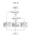
- Increase or decrease in the number of seek steps i.e., increase or decrease in the distance the head moves is dealt with by changing the number of steps included in the fixed velocity region so as not to change the curves of acceleration and deceleration.
- the acceleration region is immediately succeeded by the deceleration region as represented by broken lines 1 to 4 in Fig. 3. That is to say, control is effected by the so-called triangular seek.
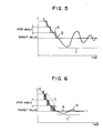
- the rotation angle of the stepping motor 4 changes as shown in Fig. 6.
- the stepping motor is configured to successively rotate while taking discrete stationary stabilized angles each time the phase excitation is changed over, i.e., for each step.
- the step commands are so suppfied as to form stairs as represented by A of Fig. 5.
- the rotation of the stepping motor follows it as represented by B of Fig. 5.
- the rotation angle of the stepping motor becomes oscillatory as represented by a period C of the rotation angle characteristics B after the stepping motor 4 reaches the target rotation angle position and the stepping operation is stopped, i.e., the phase excitation state is fixed. It thus takes tong time for the motor to converge to the target angle position and stop, the so-called settling time being elongated.
- the settling time at the completion of the head seek is desired to be short as far as possible.
- a small-sized disk unit using a stepping motor of the prior art has a problem that it is difficult to shorten the access time.
- Such a disk unit is disclosed in Japanese Patent Unexamined Publication No. 122270/80, for example.
- An object of the present invention is to shorten the so-called settling time measured from time when the rotor of the stepping motor begins to move at an arbitrary angular position to the time when the rotor stops at the next target angular position.
- Another object of the present invention is to realize shortened settling time by control means to avoid the large size of the unit attendant upon the use of mechanical means.
- a stepping motor control system according to the present invention will now be described in detail by referring to illustrated embodiments.
- the hardware configuration is the same as that of Fig. 1 of the prior art excepting that a part of changeover control between steps of phase excitation for the stepping motor 4 is effected alternately and repeatedly by using the PWM (Pulse Width Modulation) system as illustrated in Fig. 6 when the motor 4 has entered the deceleration region.
- PWM Pulse Width Modulation
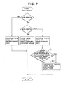
- Processing steps 10 and 20 of Fig. 7 are the modified (added) part for this embodiment.
- processing step 10 it is judged whether the stepping motor 4 has reached a step preceding the target rotation angle position by a predetermined number of step, say, 3 steps.
- step 20 alternate changeover of phase excitation using the so-called PWM is conducted.
- the stepping motor 4 must be transferred from a particular step, say, step (n-1) to the next step or step n, the excitation state at phase (m-1) corresponding to step (n-1) is not changed over directly to the excitation state at phase m corresponding to the next step n.
- any method may be used for judgment at processing step 10.
- the number of steps of the stepping motor 4 is counted, and it is judged whether the counted value has reached the number of steps up to the target value minus a predetermined value (3, for example) or not.
- the stepping motor 4 is driven as illustrated in Fig. 2.
- the answer at processing step 10 of Fig. 7 becomes YES and the processing step 20 is carried out.
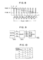
- the phase excitation state between steps takes the form of PWM as illustrated in Fig. 8 during the period D.
- the average value of excitation current at phase (n-1) successively decreases as represented by broken lines E of Fig. 8.
- the average value of excitation current at phase n is successively increased with the same rate as the above described decrease.
- the excitation state of phase n is assumed.
- the rotation of the rotor of the stepping motor 4 between steps becomes sufficiently smooth when the rotation angle approaches the target value.
- the stepping motor 4 can be stopped in an extremely short period C' causing little vibration.
- the embodiment is applied to the head seek of a disk unit, it is possible to sufficiently shorten the access time.
- the period D of Fig. 3 is composed of the last three steps of the deceleration region. So far as the last step at the stop side of the deceleration region is included, the period D may be composed of an arbitrary number of steps. It is a matter of course that the period D may be composed of all steps in the deceleration region, for example.
- this embodiment needs mainly software arrangements and need little change in hardware, resulting in cost saving.
- this embodiment can be applied not only to the above described disk unit but also to any unit using a stepping motor controlled by a microcomputer. Since only the sofiware modification is needed, this embodiment can also be applied to a system in operation easily, resulting in high universality.
- a stepping motor 100 is used for positioning the read/write head in a small-sized magnetic disk unit.
- the head is positioned on a predetermined track of the disk through a capstan, a steel belt and a carriage which are not illustrated in Fig. 9.
- the motor 100 is two-phase bipolar type, for example, and has a pair of windings ⁇ 1 and ⁇ 2 .
- Numeral 300 denotes a control section of the disk unit.
- the control section 300 has a microprocessor unit and program memory means for operating a driver 200.
- the program is shown in Figs. 14 and 15.
- Truth tables relating to Fig. 9 are shown in Figs. 10 and 11.
- the feeder p is "H" and feeder P 2 is "L"
- the polarity of the input voltage to the winding ⁇ 1 becomes as P, - P2.
- the feeder P becomes the positive pole and the feeder P2 becomes the negative pole.
- the magnitude of the input voltage is either 12 V or 5V, for example.
- the changeover of the voltage level is effected by a signal line S 3 .
- the signal line S 3 is "H”
- the voltage level becomes 12 V.
- the signal line S3 is "L”
- the voltage level becomes 5 V.
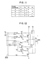
- Fig. 12 shows an example of internal configuration of the driver 200.
- a portion of the driver 200 corresponding to the winding ⁇ 1 is illustrated in Fig. 12, and a portion corresponding to the winding ⁇ 2 is omitted.
- switching transistors such as Q 1 the and Q 2 , NOT gates, and AND gates are used.
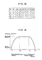
- Fig. 13 shows a truth table relating to Fig. 12.
- a signal line G n (G,, for example) shown in the table becomes "H”
- the transistor Q n Q 1 , for example
- the transistor, Q n ' also turns ON.
- the corresponding transistor is OFF.
- No. 1 to No. 4 can be considered as follows.
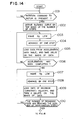
- Figs. 14 and 15 show a series of processing steps conducted from the time when the next target rotation angle for the stepping motor 100 is specified until the time when the positioning at the rotation angle is completed and the input of the next target rotation angle is waited.
- the command of the next target rotation angle is waited at step 1011 of Fig. 14.
- the contents of this command are the rotation direction and the number of steps.
- the slewing curve as illustrated in Fig. 16 is derived.
- This curve is a kind of speed pattern for acceleration and deceleration control.
- the curve is divided into the acceleration region (t, to t2), fixed velocity region (t2 to t 3 ), and deceleration region (t 3 to t 4 ).
- the pattern used in the acceleration region (t, to t2) has been predetermined to rapidly accelerate the stepping motor so far as the motor is prevented from being out of step (out of synchronism). This pattern is stored in an acceleration data table.
- the maximum velocity in the fixed velocity region (t2 to t 3 ) is also predetermined.
- the pattern of the deceleration region (t 3 to t 4 ) is also predetermined and its data are stored in a deceleration data table.
- the timing at the end of the deceleration region (t 3 to t4) of Fig. 16 is so determined that the number of steps corresponding thereto may coincide with that specified by the rotation command. If the number of steps is small, the fixed velocity region (t 2 to t 3 ) becomes short or zero. If the number of steps is further small, a higher velocity area in the deceleration region (t 3 to t 4 ) and the acceleration region (t, to t 2 ) is elminated. On the way of acceleration, therefore, deceleration is started.
- step 1003 the output of the signal line S 3 is changed to "L" (Low). As a result, the input voltage of the motor 100 is held at a high value 12 V.
- step 1004 one step is taken. This aims at changing the phase excitation shown in Figs. 10 and 11 from “C” to "B", for example. To be concrete, the signal lines S,S2 are changed from “L""L” to "H””L". As a result, the rotation phase of the stepping motor 100 advances by the unit step.
- a necessary delay is taken. This delay is a time interval between one step and the next step supplied from the acceleration data table. Since the unit step angle is constant, the delay becomes the reciprocal of the speed.
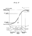
- Fig. 17 is rewritten from Fig. 16. The ordinate of Fig. 17 represents the rotation angle. The intersection resulting from dividing the rotation angle by the unit step angle width indicates the timing of each step command (processing in step 1004).
- Fig. 17 also shows states "L" and "H" of the feeder P, relating to the winding ⁇ 1 and the feeder P 3 relating to the winding ⁇ 3 .
- step 1006 it is judged whether the acceleration has been completed. That is to say, it is checked whether the time t2 (or the corresponding number of steps) is over or not. If the acceleration region is still effective, step 1003 is resumed. Otherwise step 1007 is taken.
- step 1007 the signal line S 3 is made "L". That is to say, the input voltage is made 12 V, and one step is taken at step 1008.
- the delay in step 1009 is constant.
- step 1010 it is judged whether the timing t 3 of the deceleration region is reached or not. This judgment is conducted by comparing the number of remaining steps (the number of projected steps) with the number of deceleration steps (reference value). Unless the deceleration region (t3 to t 4 ) is not reached, processing is repeated from step 1007. If the deceleration region is reached, processing is advanced to step 1011 of Fig. 15.
- the input voltage is set to 12 V.
- another step is taken.
- a necessary delay is taken.
- processing is advanced to step 1203.
- Fig. 18 is an enlarged view of a portion K shown in Fig. 18.
- the actual rotation phase of the stepping motor 100 is shown as a waveform 10. States of the signal line S3 is also shown.
- step 1203 it is judged whether the target value (command value) is reached or not by checking whether the timing t 4 previously computed at step 1002 or the number of steps corresponding thereto is reached or not. Since the feedback control is not conducted here, this is a problem on the computation level.
- step 1204 it is judged at step 1204 whether predetermined timing t s has been reached or not. In any case, step 1201 is resumed thereafter. If the timing t s is reached, however, the signal line S3 is changed over to "H" before step 1201 is resumed. As a result, the input voltage to the motor 100 is set to the lower value of 5 V.
- the timing t 5 is defined by taking the timing t 4 computed to step 1002 as reference and previously holding the value of t. -t s as a constant. This constant At ranges from zero to 2At'. As illustrated in Fig. 17, 2At' is the length of 2 steps in the fixed velocity region.
- the input voltage is changed to 5 V at step 2001.
- step 1205 it is understood that the signal line S 3 turns “H” to change the input voltage to 5 V when the target position or the timing t s is reached.
- a delay of (t 6 -t 4 ) seconds is taken at step 2002 and the signal line S3 is changed to "L” to select 12 V at step 3001. And a delay of (t7 -t 6 ) seconds is taken at step 3002, and the signal line S 3 is changed to "H” to select 5V.
- the processing is completed.
- the input voltage is changed from 12 V to 5 V at time t s , changed to 12 V at time t 6 , and changed to 5 V at time t 7 as shown in Fig. 18. In this way, 12 V is maintained until the time t 5 .
- This 12 V is the higher value and the rated value of the stepping motor 100.
- the waveform 10 of Fig. 18 is oscillatory and a settling time T s2 is required for the oscillation to disappear.
- T s t 4
- t 6 -t s 15 ms
- t 7 -t 6 10 ms
- an experiment showed that the settling time T 2 was approximately 25 ms. If 12 V was maintained over all periods in this case, the settling time T s1 was unfavorably approximately 50 ms.
- the waveform of the rotation phase at this time is represented by 10'.
- the input voltage is not changed over as represented by the waveform 10', it takes a comparatively long time (T s1 ) for the oscillation of the system to be damped because a strong pullback force is acted on the overshoot from the target value. If the input voltage is lowered to reduce the torque in this period according to the present invention, the pullback force is weakened to shorten the settling time (T s2 ). If a stepping motor originally having a low torque is used, the velocity until the target value is reached is lowered, resulting in a longer settling time.
- the aforementioned offset means a difference from the target value (command value). This is to say, the rotation phase is settled on a value displaced from the target value. Since this offset is caused in case of an insufficient torque, the input voltage is changed over to 12 V again in the period of t 6 to t7 as described before. It is desirable to define the changeover time t 6 so that the latter 50 to 20 % of the period of the settling time t s2 becomes to the 12 V period.
- the input voltage is maintained at a high value in a first proqess included in a series of processes.
- the first process means a process until the vicinity of the command value - (commanded rotation angle) is approached.
- the first process corresponds to the processing in steps 1003 and 1011 of Figs. 14 and 15.
- the input voltage is maintained at a low value.
- the second process corresponds to processing in steps 2001 and 2002.
- the processing in steps 1201 to 1205 is overlapped with the first and second processes.
- a stepping motor of two-phase bipolar type is used and the input voltage is changed over from 12 V to 5 V.
- this is only an example. Different forms may be used.
Landscapes
- Engineering & Computer Science (AREA)
- Power Engineering (AREA)
- Control Of Stepping Motors (AREA)
Applications Claiming Priority (4)
| Application Number | Priority Date | Filing Date | Title |
|---|---|---|---|
| JP79165/85 | 1985-04-16 | ||
| JP7916585A JPS61240894A (ja) | 1985-04-16 | 1985-04-16 | ステツピングモ−タ制御方式 |
| JP84484/85 | 1985-04-22 | ||
| JP8448485A JPS61244299A (ja) | 1985-04-22 | 1985-04-22 | ステツピングモ−タの制御方式 |
Publications (2)
| Publication Number | Publication Date |
|---|---|
| EP0200959A2 true EP0200959A2 (fr) | 1986-12-17 |
| EP0200959A3 EP0200959A3 (fr) | 1987-12-16 |
Family
ID=26420219
Family Applications (1)
| Application Number | Title | Priority Date | Filing Date |
|---|---|---|---|
| EP86105141A Withdrawn EP0200959A3 (fr) | 1985-04-16 | 1986-04-15 | Système de commande pour moteur pas à pas |
Country Status (2)
| Country | Link |
|---|---|
| US (1) | US4691154A (fr) |
| EP (1) | EP0200959A3 (fr) |
Cited By (3)
| Publication number | Priority date | Publication date | Assignee | Title |
|---|---|---|---|---|
| EP0535369A1 (fr) * | 1991-08-30 | 1993-04-07 | Canon Kabushiki Kaisha | Système de commande de moteur |
| EP0509681A3 (en) * | 1991-04-16 | 1993-04-21 | Hewlett-Packard Company | Method and apparatus for controlling a stepper motor |
| US5663624A (en) * | 1992-03-05 | 1997-09-02 | Hewlett-Packard Company | Closed-loop method and apparatus for controlling acceleration and velocity of a stepper motor |
Families Citing this family (13)
| Publication number | Priority date | Publication date | Assignee | Title |
|---|---|---|---|---|
| JPS6361426A (ja) * | 1986-08-22 | 1988-03-17 | Csk Corp | 光記録媒体のデ−タ追記方式 |
| GB2199167B (en) | 1986-11-29 | 1991-02-20 | Papst Motoren Gmbh & Co Kg | Rotary drive for a data storage medium |
| JP2887314B2 (ja) * | 1988-03-29 | 1999-04-26 | ソニー株式会社 | ステッピングモータの駆動方法 |
| US4890048A (en) * | 1989-01-09 | 1989-12-26 | Hunter L Wayne | Low torque ripple stepping motor controller circuit |
| US5291110A (en) * | 1991-10-31 | 1994-03-01 | Integral Peripherals, Inc. | Low acoustic noise seeking method and apparatus |
| US5583410A (en) * | 1994-10-21 | 1996-12-10 | Pitney Bowes Inc. | Method and apparatus for multiplex control of a plurality of stepper motors |
| JP3136923B2 (ja) * | 1994-10-28 | 2001-02-19 | セイコーエプソン株式会社 | パルスモータの制御装置 |
| US6144184A (en) * | 1997-08-09 | 2000-11-07 | Brother Kogyo Kabushiki Kaisha | Motor controlling method and apparatus |
| US6064171A (en) * | 1999-06-11 | 2000-05-16 | Lexmark, International, Inc. | Host based stepper motor phase controller and method therefor |
| JP3715850B2 (ja) * | 1999-11-08 | 2005-11-16 | キヤノン株式会社 | モータ制御装置及び該装置を用いたプリンタ |
| US6563285B1 (en) | 2001-06-25 | 2003-05-13 | Lexmark International, Inc. | Stepper motor control system |
| JP6458689B2 (ja) * | 2015-09-10 | 2019-01-30 | 株式会社デンソー | モータ制御装置 |
| EP3582390A4 (fr) * | 2017-02-09 | 2020-01-01 | Fuji Corporation | Dispositif de commande de moteur et dispositif d'alimentation |
Family Cites Families (4)
| Publication number | Priority date | Publication date | Assignee | Title |
|---|---|---|---|---|
| DE3265203D1 (en) * | 1981-05-02 | 1985-09-12 | Rodime Plc | Method and apparatus for controlling a stepper motor |
| US4513236A (en) * | 1982-07-22 | 1985-04-23 | Canon Kabushiki Kaisha | Control method for stepping motor |
| JPS59155072A (ja) * | 1983-02-23 | 1984-09-04 | Canon Inc | 印字装置 |
| US4600868A (en) * | 1983-05-09 | 1986-07-15 | Bryant Lawrence M | Open loop acceleration/deceleration control for disk drive stepper motors |
-
1986
- 1986-04-15 EP EP86105141A patent/EP0200959A3/fr not_active Withdrawn
- 1986-04-16 US US06/852,756 patent/US4691154A/en not_active Expired - Fee Related
Cited By (4)
| Publication number | Priority date | Publication date | Assignee | Title |
|---|---|---|---|---|
| EP0509681A3 (en) * | 1991-04-16 | 1993-04-21 | Hewlett-Packard Company | Method and apparatus for controlling a stepper motor |
| EP0535369A1 (fr) * | 1991-08-30 | 1993-04-07 | Canon Kabushiki Kaisha | Système de commande de moteur |
| US5327063A (en) * | 1991-08-30 | 1994-07-05 | Canon Kabushiki Kaisha | Method of controlling a stepping motor |
| US5663624A (en) * | 1992-03-05 | 1997-09-02 | Hewlett-Packard Company | Closed-loop method and apparatus for controlling acceleration and velocity of a stepper motor |
Also Published As
| Publication number | Publication date |
|---|---|
| EP0200959A3 (fr) | 1987-12-16 |
| US4691154A (en) | 1987-09-01 |
Similar Documents
| Publication | Publication Date | Title |
|---|---|---|
| US4691154A (en) | Stepping motor control system | |
| US4489259A (en) | Method and apparatus for controlling a stepper motor | |
| US5381279A (en) | Disk drive system with adjustable spindle and actuator power to improve seek and access performance | |
| JP2978594B2 (ja) | ステッピングモータの制御方式 | |
| JP4542668B2 (ja) | パルス発振ic並びにそのicを使用したモータの位置決め制御方法とその装置 | |
| US4803414A (en) | Method of controlling a step motor | |
| US4788484A (en) | Method and apparatus for driving a stepper motor with multiple voltages | |
| US4982146A (en) | Stepping motor driving device | |
| JP2003224998A (ja) | ステッピングモータ駆動方法 | |
| US4810946A (en) | Adaptive pulsing motor control for positioning system | |
| US6072656A (en) | Stepping motor control method | |
| US7701162B2 (en) | Method for controlling stepping motor | |
| US4703242A (en) | Control method and apparatus for positioning servo system | |
| JPS61244299A (ja) | ステツピングモ−タの制御方式 | |
| JPH04133696A (ja) | ステップモータ駆動方式 | |
| JP2576877B2 (ja) | ステップモータ駆動装置及びヘッド移動装置 | |
| JPH0715358Y2 (ja) | ステッピングモータ制御回路 | |
| JPS6395896A (ja) | 磁気デイスクドライブのステツピングモ−タ駆動方法 | |
| JPS637197A (ja) | ステッピングモータの駆動制御方法 | |
| JPH04222970A (ja) | 磁気ディスク装置 | |
| JPH02188195A (ja) | ステップモータの駆動制御装置 | |
| JPH08241129A (ja) | サーボ定数の切り替え方法 | |
| JPS5998351A (ja) | 磁気デイスク装置の磁気ヘツド駆動用ステツピングモ−タの停止方式 | |
| JPS59156192A (ja) | ステツピングモ−タの制御方式 | |
| JPH0265695A (ja) | ステツピングモータの停止時における振動抑制方法 |
Legal Events
| Date | Code | Title | Description |
|---|---|---|---|
| PUAI | Public reference made under article 153(3) epc to a published international application that has entered the european phase |
Free format text: ORIGINAL CODE: 0009012 |
|
| AK | Designated contracting states |
Kind code of ref document: A2 Designated state(s): DE FR GB IT SE |
|
| PUAB | Information related to the publication of an a document modified or deleted |
Free format text: ORIGINAL CODE: 0009199EPPU |
|
| RA1 | Application published (corrected) |
Date of ref document: 19861217 Kind code of ref document: A2 |
|
| PUAL | Search report despatched |
Free format text: ORIGINAL CODE: 0009013 |
|
| AK | Designated contracting states |
Kind code of ref document: A3 Designated state(s): DE FR GB IT SE |
|
| 17P | Request for examination filed |
Effective date: 19871214 |
|
| 17Q | First examination report despatched |
Effective date: 19891213 |
|
| STAA | Information on the status of an ep patent application or granted ep patent |
Free format text: STATUS: THE APPLICATION HAS BEEN WITHDRAWN |
|
| 18W | Application withdrawn |
Withdrawal date: 19900420 |
|
| R18W | Application withdrawn (corrected) |
Effective date: 19900420 |
|
| RIN1 | Information on inventor provided before grant (corrected) |
Inventor name: ISHIBASHI, AKIRA Inventor name: KATO, KAZUTOSHI Inventor name: SATO, MASAHIKO Inventor name: MATSUSHITA, TSURUMASA |