EP0201202B2 - Méthode de production de tôle plaquée par laminage à chaud - Google Patents
Méthode de production de tôle plaquée par laminage à chaud Download PDFInfo
- Publication number
- EP0201202B2 EP0201202B2 EP86302508A EP86302508A EP0201202B2 EP 0201202 B2 EP0201202 B2 EP 0201202B2 EP 86302508 A EP86302508 A EP 86302508A EP 86302508 A EP86302508 A EP 86302508A EP 0201202 B2 EP0201202 B2 EP 0201202B2
- Authority
- EP
- European Patent Office
- Prior art keywords
- rolling
- materials
- cover
- base material
- cladding
- Prior art date
- Legal status (The legal status is an assumption and is not a legal conclusion. Google has not performed a legal analysis and makes no representation as to the accuracy of the status listed.)
- Expired - Lifetime
Links
Images


Classifications
-
- B—PERFORMING OPERATIONS; TRANSPORTING
- B23—MACHINE TOOLS; METAL-WORKING NOT OTHERWISE PROVIDED FOR
- B23K—SOLDERING OR UNSOLDERING; WELDING; CLADDING OR PLATING BY SOLDERING OR WELDING; CUTTING BY APPLYING HEAT LOCALLY, e.g. FLAME CUTTING; WORKING BY LASER BEAM
- B23K20/00—Non-electric welding by applying impact or other pressure, with or without the application of heat, e.g. cladding or plating
- B23K20/04—Non-electric welding by applying impact or other pressure, with or without the application of heat, e.g. cladding or plating by means of a rolling mill
-
- Y—GENERAL TAGGING OF NEW TECHNOLOGICAL DEVELOPMENTS; GENERAL TAGGING OF CROSS-SECTIONAL TECHNOLOGIES SPANNING OVER SEVERAL SECTIONS OF THE IPC; TECHNICAL SUBJECTS COVERED BY FORMER USPC CROSS-REFERENCE ART COLLECTIONS [XRACs] AND DIGESTS
- Y10—TECHNICAL SUBJECTS COVERED BY FORMER USPC
- Y10S—TECHNICAL SUBJECTS COVERED BY FORMER USPC CROSS-REFERENCE ART COLLECTIONS [XRACs] AND DIGESTS
- Y10S29/00—Metal working
- Y10S29/032—Rolling with other step
-
- Y—GENERAL TAGGING OF NEW TECHNOLOGICAL DEVELOPMENTS; GENERAL TAGGING OF CROSS-SECTIONAL TECHNOLOGIES SPANNING OVER SEVERAL SECTIONS OF THE IPC; TECHNICAL SUBJECTS COVERED BY FORMER USPC CROSS-REFERENCE ART COLLECTIONS [XRACs] AND DIGESTS
- Y10—TECHNICAL SUBJECTS COVERED BY FORMER USPC
- Y10S—TECHNICAL SUBJECTS COVERED BY FORMER USPC CROSS-REFERENCE ART COLLECTIONS [XRACs] AND DIGESTS
- Y10S29/00—Metal working
- Y10S29/048—Welding with other step
-
- Y—GENERAL TAGGING OF NEW TECHNOLOGICAL DEVELOPMENTS; GENERAL TAGGING OF CROSS-SECTIONAL TECHNOLOGIES SPANNING OVER SEVERAL SECTIONS OF THE IPC; TECHNICAL SUBJECTS COVERED BY FORMER USPC CROSS-REFERENCE ART COLLECTIONS [XRACs] AND DIGESTS
- Y10—TECHNICAL SUBJECTS COVERED BY FORMER USPC
- Y10T—TECHNICAL SUBJECTS COVERED BY FORMER US CLASSIFICATION
- Y10T29/00—Metal working
- Y10T29/49—Method of mechanical manufacture
- Y10T29/4981—Utilizing transitory attached element or associated separate material
-
- Y—GENERAL TAGGING OF NEW TECHNOLOGICAL DEVELOPMENTS; GENERAL TAGGING OF CROSS-SECTIONAL TECHNOLOGIES SPANNING OVER SEVERAL SECTIONS OF THE IPC; TECHNICAL SUBJECTS COVERED BY FORMER USPC CROSS-REFERENCE ART COLLECTIONS [XRACs] AND DIGESTS
- Y10—TECHNICAL SUBJECTS COVERED BY FORMER USPC
- Y10T—TECHNICAL SUBJECTS COVERED BY FORMER US CLASSIFICATION
- Y10T29/00—Metal working
- Y10T29/49—Method of mechanical manufacture
- Y10T29/49826—Assembling or joining
- Y10T29/49885—Assembling or joining with coating before or during assembling
-
- Y—GENERAL TAGGING OF NEW TECHNOLOGICAL DEVELOPMENTS; GENERAL TAGGING OF CROSS-SECTIONAL TECHNOLOGIES SPANNING OVER SEVERAL SECTIONS OF THE IPC; TECHNICAL SUBJECTS COVERED BY FORMER USPC CROSS-REFERENCE ART COLLECTIONS [XRACs] AND DIGESTS
- Y10—TECHNICAL SUBJECTS COVERED BY FORMER USPC
- Y10T—TECHNICAL SUBJECTS COVERED BY FORMER US CLASSIFICATION
- Y10T29/00—Metal working
- Y10T29/49—Method of mechanical manufacture
- Y10T29/49826—Assembling or joining
- Y10T29/49888—Subsequently coating
Definitions
- the present invention relates to a method for producing a metal clad plate by hot-rolling.
- the present invention uses relatively inexpensive high-strength materials, for example, steel or copper alloy, as the base material, and as the cladding materials, uses metallic materials having a special function, such as stainless steel, iron-based superalloy, nickel-based superalloy, cobalt-based superalloy, nickel or its alloy, titanium or its alloy, zirconium or its alloy, alluminum or its alloy, copper or copper alloy, or the like.
- the products may be single clad or multiple clad.
- the bonding boundary is contaminated by oxide, carbide or non metallic inclusions, which cause bonding between the base metal and the cladding material to become difficult, or which make it difficult to obtain a satisfactory bonding strength even if the bonding is attained.
- Japanese Unexamined Patent Publication No. 56-122681 discloses a cladding method using titanium-or titanium-alloy-cladding material, in which the composition of the steel-base material is adjusted such that the carbon content is 0.07 wt.% or less and a carbon-fixing element is added.
- a steel sheet having the composition similar to the base steel material is inserted between the cladding material and base material.
- the proposed method could, at the cladding material position, reduce the amount of carbon diffusing from the base material to cladding material. Nevertheless, oxide, carbide, and nonmetallic inclusions were detected at an appreciable amount exceeding the permissible limit on the bonding boundary region of the clad plates when the applicant produced steel sheets by the above publication method.
- EP-A-132,937 discloses a method of forming a clad plate by rolling a laminated assembly. The surfaces to be bonded are cleared and are protected by an inert gas atmosphere during rolling.
- AT-B-357,008 disclosed a method for producing a clad plate by rolling, comprising the steps of forming a multi-layer structure in which a base material, a cladding material and a cover material are overlaid on each other to form a multi-layer structure, a further such multi-layer structure is formed, a pair of said multi-layer structures are overlaid in such a manner that the cover materials face one another via a separating agent, the pair of base materials of said multi-layer structures are welded to one another along a periphery thereof, thereby forming a blank for rolling in which said base materials function as material for preventing warp, said blank is hot rolled, a rolled article is cut along its periphery to separate said pair of structures along said separating agent, and subsequently said cover materials are removed.
- GB 755,333 discloses a method similar to that of AT-B-357,008.
- the interior of the laminated assembly is exhausted and a gap is shown around the periphery of the interior sheets, so that all the interfaces between the laminated sheets communicate with each other.
- the first object of the present invention is to provide a method for producing a clad plate having a high bonding strength.
- the second object of the present invention is to provide a method for producing a clad plate by rolling, which allows a lessening of the warp of a clad plate during or after the rolling.
- the third object of the present invention is to provide a clad plate-producing method which attains an improved accuracy in the sheet thickness of a clad plate, and which, during the straightening, results in neither buckling of a clad plate nor destruction of the bonding portion of a clad plate.
- the fourth object of the present invention is to provide a clad plate-producing method which promotes separation of the warp-preventing material from a clad plate.
- a method for producing a clad plate by rolling comprising the steps of forming a multi-layer structure in which a base material, a cladding material and a cover material are overlaid on each other, a material for preventing warp is overlaid over an outer surface of said cover material via a separating agent, said material for preventing warp and said base material are fixed to one another by welding along a periphery thereof, thereby forming a blank for rolling, said blank is hot-rolled, a rolled article is cut along its periphery to separate said material for preventing warp, and subsequently, said cover material is removed, characterised in that
- the invention also provides a method for producing a clad plate by rolling, comprising the steps of forming a multi-layer structure in which a base material, a cladding material and a cover material are overlaid on each other to form a multi-layer structure, a further such multi-layer structure is formed, a pair of said multi-layer structures are overlaid in such a manner that the cover materials face one another via a separating agent, the pair of base materials of said multi-layer structures are welded to one another along a periphery thereof, thereby forming a blank for rolling in which said base materials function as material for preventing warp, said blank is hot rolled, a rolled article is cut along its periphery to separate said pair of structures along said separating agent, and subsequently said cover materials are removed, characterised in that
- the cleaning of the contact surfaces of the cover material and cladding material is intended to utilize the effect of solution (1) as described above, to the greatest degree, and also is intended to attain a satisfactory bonding by removing from the space, in which the cladding material is situated, as much as is industrially possible of any component deterimental to the bonding.
- Both surfaces of cladding material are thus completely joined with the cover and base materials and the cladding material is rolled while being satisfactorily restrained therebetween. As a result, warp can be prevented and a uniform deformation can be attained.
- the blank for rolling does not warp during heating, rolling, and cooling, or during heat treatment. Accordingly, the operation problems in a rolling mill and heat treatment furnace caused by warp do not occur. In addition, a uniform working is attained so that the dimensional accuracy is improved and the bonding strength is enhanced, since the blank is subjected to neither forcible bending nor unbending.
- the warp-preventing material desirably has the same composition and dimension as the separation-destined surface of the base material.
- the thickness of the warp preventing material can be decreased to one third of the thickness of the base material by utilizing the difference in cooling speeds between the base material and the warp preventing material, if these materials are of the same kind.
- the warp-preventing material thicker than the base material, since the cost is thereby enhanced.
- a multi-layer structure obtained by solution (1) is used, in such a way that this one structure having virtually the same dimension as the other multi-layer structure is joined with the other multi-layer structure via the cover material, and a pair of the multi-layer strucures are fixed by welding a pair of the base materials. In this case, two clad plates are simultaneously produced.
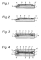
- FIG. 1 an intermediate step of producing a blank for rolling by assembling the sheet materials is shown.
- the cladding material 2 is overlaid on the base material 1.
- the cover material 3 is preliminarily subjected to welding to attach lugs on the circumferential part thereof.
- the cover material 3 is overlaid on the cladding material 2 and is fixed to the base material 1 by the fillet welding 4.
- the cladding material 2 is contained in the space formed by the cover material 3 and the base material 1.
- Nozzles 5 and 5' are provided for blowing, during the fillet welding, an inert gas such as argon or helium through one of the nozzles 5 and 5'.
- an inert gas such as argon or helium
- the end of the cover material 3 is bent and is fillet-welded to the base material 1.
- the other procedures are the same as in Fig. 1.
- the multi-layer structures shown in Figs. 1 and 2 are later further subjected to the welding and fixing of the warp-preventing material on the circumference thereof.
- the multi-layer structures are provided with a pair of the nozzles 5, 5', during the fillet welding, preferably, the nozzle 5' is closed, the surface of cover material is heated to 100 ° C or higher, and the gas is exhausted through the nozzle 5 to attain a reduced pressure of 10- 1 torr or less.
- the warp-preventing material 6 can be faced to the multi-layer structure of Fig. 1, for example, as shown in Fig. 3.
- the base material 1 and warp-preventing material 6 are welded (7) therebetween.
- the pressure reduction to attain 10 1 torr or less is continuously carried out by utilizing the nozzle 5 and the welding heat.
- a blank for rolling is produced by the above described procedure and is heated to a predetermined temperature followed by hot-rolling.
- the rolled article is cut, so that the warp-preventing material is separated therefrom.
- the cover material 3 is removed by machining, grinding or polishing, to expose the surface of the cladding material 2, and the clad plate is thus obtained.
- a pair of the multi-layer structures shown in Fig. 1 are joined via an oxide layer 9 formed on at least one of the joining surfaces.
- the oxide layer may be formed by preliminarily oxidizing the joining surface(s) to a thickness of 30 /1.m or more, or by applying the powder of any one or more of A1 2 0 3 , Si0 2 , Ti0 2 , Cr 2 0 3 , Fe 2 0 3 , and Fea0 4 , with resin as the vehicle, to a thickness of 10 ⁇ m or more, and then drying.
- the base material 1 and 1' are welded (7) to one another therebetween, preferably during the pressure reduction through the nozzles 5 to attain 10 1 torr or less.
- the base material 1 and 1' have the function of warp prevention in the embodiment shown in Fig. 4.
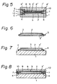
- Fig. 5 The embodiment illustrated in Fig. 5 is the same as that shown in Fig. 4 except that the multi-layer structure shown in Fig. 2 is used, and further, a distant piece 10 is inserted between the cover materials 3 to prevent their destruction due to the welding.
- the blanks for rolling shown in Figs. 3, 4, and 5 are subjected to forge welding or fusion welding for dosing the nozzles 5, while the pressure reduction to 10 1 torr or less is continued through the nozzles 5. After this, the blanks are heated and then hot-rolled.
- the rolled article is cut and separated between the cover materials 3, 3'
- the cover materials 3, 3' are then removed by machining, grinding or pickling to expose the cladding material. Two clad plates are obtained from each cut section.
- the cover material is most appropriately made of carbon steel free of alloying elements since it is inexpensive and easily formed.
- An alloying element may be however contained in the steel provided that its carbon content is 0.01% or less.
- the thickness of a cover steel sheet after the roll finishing is determined from its sheet strength required during assembling a blank, and also the distance of carbon diffusion during the rolling.
- the thickness mentioned above is desirably 0.1 mm or more, which is the distance of carbon diffusion mentioned above.
- the thickness of a cover steel sheet, when a blank is assembled, is therefore equal to the thickness after the rolling finishing, multiplied by the roll-reduction ratio, i.e., 0.1 x total thickness of a blank/total thickness of a finished article (mm).
- a foil or plating layer is inappropriate as the cover steel material.
- the heating temperature exceeds 900 °C
- the carbon or carbide in the cover material vaporizes toward or diffuses into the cladding material, with the result that prominent carburization of the cladding material occurs. This impairs the bending or shear properties of clad products.
- the heating temperature desirably exceeds the recrystallization temperature, i.e., 650 ° C, of the materials in the light of the deformation energy required for rolling.
- the cladding material is fixed to the base material by means of the cover material, and the cover material is fixed to the base material by welding the circumference of the cover material. This prevents a displacement of the cladding material, rupture of the cover material, and nonuniform deformation of these materials from occurring during their working. Since the dimensional accuracy of a clad plate is impaired by the nonuniform deformation, the fixing method according to the present invention is effective for enhancing the dimensional accuracy of a clad plate.
- both surfaces of the cladding material can be joined with the opposite materials and the cladding material is rolled while being thoroughly restrained. This prevents warp and attains a uniform deformation.
- FIG. 6 an intermediate step of assembling a roll blank is illustrated.
- the cladding material 2 is cleaned, and the surface of the cover material to be brought in contact with the cladding material 2 is cleaned.
- the cover material is, in this embodiment, two cover steel sheets 3, 3' having a carbon content of preferably 0.01 wt% or less.
- the cover steel sheets 3, 3' are overlaid on the cladding material 2 to form a multi-layered structure.
- the cover steel sheets 3, 3' are welded to one another along the four peripheral ends thereof.
- the cladding material 2 is sewed inside the cover steel-sheets 3, 3'.
- Inert gas such as argon or helium, or a non-oxidizing gas such as nitrogen or carbon dioxide gas, is desirably blown through the nozzle 5, to prevent contamination of the cladding material 2 and cover steel-sheets 3, 3' with the fume and spatter of welding.
- the nozzle 5 is dosed.
- the surfaces of the cover steel-sheets 3, 3' are heated to 100 ° C or higher and the pressure in the space formed by the cover steel-sheets 3, 3' and cladding material 2 is reduced to 10 1 torr or less while the heating mentioned above is continued.
- the heating of the surfaces of the cover steel-sheets 3, 3' is effective for removing moisture and organic material, and the pressure reduction is further effective for this objective and for preventing oxidation of the bonding-destined surfaces.
- the cover steel-sheet 3' is welded to the cover steel-sheet 3 along their four peripheral ends (Fig. 6) and is subsequently welded to the base material 1, as is shown in Fig. 7.
- the welding of the cover steel sheet 3' and base metal 1 may be carried out in any sequence other than that shown in Figs. 6 and 7, which however at most facilitates the welding operation and maintains the cleanliness of bonding-destined surfaces.
- the separating agent 9 is disposed on the cover steel-sheet 3 and the warp-preventing mateial 6 is overlaid on the cover steel-sheet 3 via the separating agent 9.
- the separating agent 9 is the same as that described hereinabove.
- the warp-preventing material 6 and the base material 1 are welded (7) to one another along the four peripheral ends thereof. Between the four peripheral welding parts (7) and the cladding and cover materials are interposed distant pieces 10, which completely shield the cladding and cover materials from a detrimental influence of the four end peripheral welding (7).
- the reinforcing materials 11, 11' Since the periphery of the reinforcing materials 11, 11' is fixed to the base material 1, the reinforcing materials 11, 11' are forced to engage into the base materials 1, l' and cladding materials 2, 2' by the initial light rolling, thereby determining the lateral position of the cladding materials 2, 2' relative to the base materials 1, 1'.
- the base materials 1, 1' and the cladding materials 2, 2' are directly bonded to one another at portions thereof exposed through the net wires of the reinforcing materials 11, 11', and they (1, 1', 2, 2') are bonded via the net wires at the other portions.
- the bonding boundary between three kinds of materials 1 (1'), 2 (2'), and 11 (11') exhibits a wave form having geometrically a destruction stopping effect.
- the bonding property attained by the three kinds of materials 1 (1'), 2 (2'), and 3 (3') can be higher than that attained by the direct bonding of the base material and the cladding material, when the reinforcing materials 11, 11' are appropriately selected so as to function as bonding-intermediary materials.
- the deformation amount of the cladding materials 2, 2', relative to that of the base materials 1, l' can be kept to a minimum, so that the thickness deviation (the maximum thickness- the minimum thickness) of a clad plate after rolling can be lessened and the dimensional accuracy can be enhanced.
- a clad plate is preferably subjected to a compulsory cooling to a temperature where the diffusion speed is satisfactorily low, i.e., 650 ° C, or lower, to suppress the diffusion across the bonding boundary to a diffusion amount as small as possible. Since, during the compulsory cooling warp is likely to occur, this procedure should be carried out while repeating the straightening.
- an at least one alternate pass of a correction or straightening operation is preferably carried out at a temperature region of blue brittleness, i.e., from 200 to 500 ° C, thereby enlarging the destruction at a part of the separation-destined surfaces to the entire surfaces.
- a temperature region of blue brittleness i.e., from 200 to 500 ° C
- the materials other than the cladding material are 0.17% carbon steel.
- the assembled blanks are 150 mm in width and 200 mm in length. These blanks are samples having a small size but allowing an evaluation of the circumustance of the rolling in the commercial production scale. All of the blanks are MIG-welded, while blowing argon gas into the blanks to prevent welding contamination. When the welding is completed, the pressure within the blanks is reduced to 10 2- torr (1,333 Pa). The heating temperature for rolling is 800 ° C for all of the blanks.
- a 6 mm thick stainless steel JIS standard SUS304
- a great warp toward the SUS304 side occurs during the rolling, the warp increases during cooling, and a thickness deviation (maximum thickness - minimum thickness) of a clad plate amounts to 0.33 mm, which is great.
- the shear strength is low and the result of a lateral bending test is poor.
- the blank has a multi-layer structure such as shown in Fig. 5 but does not have the cover materials 3, 3'.
- the shear strength is low, and in the method 1.2, the result of the lateral bending test is poor.
- the blanks of the methods 1.3 through 1.7 according to the present invention have a structure according to one of Figs. 3 through 5.
- the blanks are provided with a non-symmetrical structure so as to make the warp appreciable.
- the warp of the clad plates generated during rolling and cooling lies within a permissible range.
- the thickness variation of the clad plates, shear strength of the base material and cladding material, and the result of the lateral test are all excellent.
- the separating agent is a 35 ⁇ m thick oxide scale which is preliminarily formed on the cover material, i.e., the steel sheet.
- the powder mainly composed of A1 2 0 3 , Ti0 2 , or Cr 2 0 3 as given in Table 1 was applied on the steel sheet, utilizing silicone resin as the vehicle, and then dried to form a 10 ⁇ m or more thick coating.
- the separating agent can be easily separated from the clad plates after rolling. After rolling, the cover material, which bonds with the cladding material, is removed by means of grinding with a grinder.
- clad plates having a high dimensional accuracy and improved bonding strength can be produced.
- the cladding material and base material are weldable to one another, any combination of metals may be employed for forming a clad plate by either hot- or cold- rolling according to the present invention.
- the base steel material is 0.17%C-carbon steel
- the cover material is 0.01% ultra low-carbon steel.
- the assembled blanks are 150 mm in width and 200 mm in length. These blanks are samples having a small size but allowing an evaluation of the circumustance of the rolling in the commercial production scale. All of the blanks are MIG-welded, while blowing argon gas into the blanks to prevent welding contamination. When the welding is completed, the pressure within the blanks is reduced to 10 2 torr. The heating temperature for rolling is 800 ° C for all of the blanks.
- a 6 mm thick stainless steel (JIS standard SUS304) is fillet-welded with a 20 mm thick base, steel material.
- JIS standard SUS304 JIS standard SUS304
- the shear strength is low and the result of the lateral bending test is poor.
- the blank has a multi-layer structure such as shown in Fig. 9 but not having the cover materials 3, 3'.
- the 25 shear strength is low, and in the method 2.2, the result of lateral bending test is poor.
- the blanks of the methods 2.3 and 2.4 according to the present invention have a structure as shown in Figs. 8 and 9, respectively.
- the blanks are provided with a nonsymmetrical structure to make the warp appreciable.
- the warp of the clad plates generated during rolling and cooling lies within a permissible range.
- the thickness variation of the clad plates, shear strength of the base material and cladding material, and the result of the lateral test are all excellent.
- the shear strength and testing result of the lateral bending have a relationship with the distribution thickness of carbides enriched in the vicinity of the bonding boundary.
- the carbides are mainly TiC when the cladding material is titanium or its alloy, and the carbides are mainly Cr 7 C 3 and Cr 23 C 6 when the cladding or cover material is stainless steel.
- the concentrated distance of carbides at the bonding boundary is measured by using an EPMA produced by Shimazu Seisakusho (model: EMX-SM), under the conditions: 20 kV acceleration voltage; 0.01 ⁇ A specimen-current, and, I u.m beam diameter. The beam was displaced from the steel to titanium sides vertically across the bonding boundary, so as to obtain a linear analysis chart of the carbon, as shown in Fig. 13.
- the 0.5k counts of carbon correspond to the full scale of the recording paper of the EPMA.
- the distance, such as shown by the arrow in Fig. 13, of boundary where the carbon concentrates, is measured as the carbon concentrated distance.
- Figure 14 shows the relationships between the shear strength measured by the method stipulated in JIS G 3603 and the carbon concentrated distance.
- the shear strength of 14 kgf/mm 2 or more stipulated in JIS G 3603 is accomplished at the carbon concentrated distance of 20 um or less.
- Carbon concentrated in the bonding boundary of titanium and steel forms TiC enhances the shear strength when the TiC amount is trace. When TiC is formed in such a degree that the carbon concentrated distance exceeds 20 ⁇ m, embrittlement rather than strengthening occurs and, therefore, some of the clad plates exhibit a low shear strength.
- a clad steel having a high bonding strength can be produced while avoiding oxidation of the cladding material which is expensive.
- the steel sheet used for cover material has a carbon content of 0.01 % or less, the strength enhancement is outstanding for the clad plates, whose cladding material easily forms carbide, as do titanium or its alloy, zirconium, or stainless steel.
- the base material may be steel having a carbon content of 0.12% or more according to the present invention while stabilizing the test values of the shear strength at a high level. Contrary to this, the shear strength is low and greatly varies when the steel having a carbon content of 0.12% or more is used as the base material in the conventional methods.
- all of the cladding materials 1, 1', cover materials 4, 4' and warp-preventing material 6 are 0.17% carbon steel.
- the thickness of these materials are given in Table 3.
- the assembled blanks are 150 mm in width and 200 mm in length. These blanks are samples having a small size but allowing an evaluation of the circumstance of the rolling in the commercial production scale.
- All of the blanks are MIG-welded, while blowing the argon gas into the blanks, to prevent welding contamination.
- the pressure within the blanks is reduced to 10- 2 torr.
- the heating temperature for rolling is 800 ° C for all of the blanks.
- reinforcing materials 11, 11' in the form of a net are inserted between the base materials 1, 1' and cover materials 2, 2'.
- the periphery of the reinforcing materials 11, 11' and the cover materials 3, 3' are fixed to the base materials 1, 1' by welding.
- the reinforcing materials 11, 11' in the form of a net are SUS 430 stainless steel, whose deformation resistance during rolling is higher than any of 0.17% carbon steel, brass and titanium.
- the reinforcing materials in the form of a net are not used and the 6 mm thick SUS 430 stainless steel (cladding material) is directly welded to the 20 mm thick base steel material.
- the 6 mm thick SUS 430 stainless steel cladding material
- a great warp toward the SUS 430 side occurs during the hot-rolling, the warp increases during cooling, and a thickness deviation and shear strength of the base material and cladding material are inferior to those obtained by the method 3.3 according to the present invention.
- the blanks for rolling in the methods 3.4 through 3.7 have the same structures as shown in Figs. 11 and 12. Any warp occurring during rolling or cooling is kept within a permissible range. In addition, the thickness deviation of the clad plates, shear strength of the base material and cladding material, and testing result of the lateral bending are excellent.
- the separating agent is a 35 um thick oxide scale pre liminarily formed on one of the surfaces the steel sheets, i.e., the cover materials 4, 4'.
- the powder mainly composed of A1 2 0 3 , Ti0 2 , or Cr 2 0 3 as given in Table I was applied on the steel sheet by utilizing silicone resin as the vehicle, and then dried to form a 10 um or more thick coating.
- the separating agent can be easily separated from the clad plates after rolling. After rolling, the cover material, which bonds with the cladding material, is removed by means of grinding with a grinder.
- the clad plate according to the present invention having a high bonding strength, can be produced by rolling. Furthermore the method according to the present invention can be applied generally for the production of a clad plate by plastic working.
- the cladding material clad on the base steel material may be stainless steel, iron-, nickel-, or cobalt-based superalloy, titanium or its alloy, aluminium or its alloy, and copper or its alloy.
- the method according to the present invention can be applied for the mill-rolling, forging, drawing, and dies-rolling methods which may be either a hot or cold-working method.
- the clad materials may have various shapes of sheet, tube, bar, rod, and others.
- the blank for rolling is not provided with the cover material 3 but the inert gas-blowing during welding and the subsequent pressure-reduction are carried out under the conditions which are adjusted to be as identical to the methods 4.3 through 4.5 as possible.
- the comparative methods 4.1 and 4.2 are therefore improved over the conventional method.
- the temperature of the final pass is higher than the A 1 transformation point, so that the warp becomes great after cooling due to the A 1 transformation occurring during cooling.
- the comparative methods 4.1 and 4.2 are inferior to the methods 4.3 through 4.5 according to the present invention, in which the final pass is carried out at a temperature lower than the A 1 transformation point (726 ° C).
- the A 1 transformation therefore, is virtually completed during the rolling and thus the warp occurrence during cooling is small.
- the A 1 transformation heat is utilized during rolling, and therefore, the temperature drop during cooling is small.
- rapid cooling is carried out after the rolling finishing, to suppress the diffusion across the bonding boundary, thus improving the shear strength and lateral bending.
- the means for suppressing the diffusion to the minimum level proposed herein greatly improves the bonding property of clad materials.
- the base material must be steel when the A 1 transformation heat is to be utilized during the rolling.
- the base material can be any material which undergoes transformation and generates transformation-heat during cooling.
- the cladding material may be any material having a melting point higher than the transformation point, e.g., the A 1 transformation point.
- stainless steels, alloy steels and titanium or its alloy have a melting point higher than the A 1 transformation point.
Landscapes
- Engineering & Computer Science (AREA)
- Mechanical Engineering (AREA)
- Pressure Welding/Diffusion-Bonding (AREA)
Claims (14)
Applications Claiming Priority (10)
| Application Number | Priority Date | Filing Date | Title |
|---|---|---|---|
| JP7238185A JPS61232075A (ja) | 1985-04-05 | 1985-04-05 | 圧延クラツド材の製造法 |
| JP72381/85 | 1985-04-05 | ||
| JP7559285A JPS61235085A (ja) | 1985-04-10 | 1985-04-10 | 圧延クラツドの製造法 |
| JP75591/85 | 1985-04-10 | ||
| JP75592/85 | 1985-04-10 | ||
| JP7559185A JPS61235084A (ja) | 1985-04-10 | 1985-04-10 | 圧延クラツド鋼の製造方法 |
| JP29928385A JPS62158583A (ja) | 1985-12-28 | 1985-12-28 | 圧延クラツド鋼板の製造法 |
| JP29928685A JPS62158584A (ja) | 1985-12-28 | 1985-12-28 | 圧延クラッド鋼板の製造方法 |
| JP299283/85 | 1985-12-28 | ||
| JP299286/85 | 1985-12-28 |
Publications (3)
| Publication Number | Publication Date |
|---|---|
| EP0201202A1 EP0201202A1 (fr) | 1986-11-12 |
| EP0201202B1 EP0201202B1 (fr) | 1989-07-26 |
| EP0201202B2 true EP0201202B2 (fr) | 1994-08-31 |
Family
ID=27524384
Family Applications (1)
| Application Number | Title | Priority Date | Filing Date |
|---|---|---|---|
| EP86302508A Expired - Lifetime EP0201202B2 (fr) | 1985-04-05 | 1986-04-04 | Méthode de production de tôle plaquée par laminage à chaud |
Country Status (3)
| Country | Link |
|---|---|
| US (1) | US4831708A (fr) |
| EP (1) | EP0201202B2 (fr) |
| DE (1) | DE3664588D1 (fr) |
Families Citing this family (34)
| Publication number | Priority date | Publication date | Assignee | Title |
|---|---|---|---|---|
| EP0291075B1 (fr) * | 1987-05-13 | 1994-12-14 | Sumitomo Electric Industries Limited | Supraconducteur composite et sa méthode de fabrication |
| DE3823760A1 (de) * | 1988-07-13 | 1990-01-18 | Peroxid Chemie Gmbh | Ventilmetall/platinverbundelektrode |
| GB9121147D0 (en) * | 1991-10-04 | 1991-11-13 | Ici Plc | Method for producing clad metal plate |
| US5222282A (en) * | 1992-01-13 | 1993-06-29 | Texas Instruments Incorporated | Method for reducing thickness of a high-strength low-ductility metal foil on thin strip element |
| JPH06182499A (ja) * | 1992-12-22 | 1994-07-05 | Mitsubishi Heavy Ind Ltd | 連続鋳造装置の冷却ドラム及びその製造方法 |
| USH1863H (en) * | 1995-03-13 | 2000-10-03 | General Electric Company | Composite fabrication process to achieve flatness |
| JPH1023737A (ja) * | 1996-07-04 | 1998-01-23 | Daido Metal Co Ltd | リニアモータ用二次コイル板 |
| US6015080A (en) * | 1997-04-01 | 2000-01-18 | Turner; William C. | Method of manufacturing clad metal plates |
| DE19747257C2 (de) * | 1997-10-25 | 2001-04-26 | Geesthacht Gkss Forschung | Vorrichtung zur Kapselung von Rohlingen aus metallischen Hochtemperatur-Legierungen |
| US6554178B1 (en) | 1999-04-08 | 2003-04-29 | Quallion Llc | Battery case feedthrough |
| US6716554B2 (en) * | 1999-04-08 | 2004-04-06 | Quallion Llc | Battery case, cover, and feedthrough |
| MY126609A (en) * | 1999-07-28 | 2006-10-31 | Nx Infrastructure Ltd | Process for manufacturing corrosion resistant metal products. |
| EP1466999B1 (fr) * | 2001-12-19 | 2014-10-08 | JX Nippon Mining & Metals Corporation | Procede pour assembler une cible en substance magnetique avec une plaque dorsale, et cible en substance magnetique |
| US8387228B2 (en) | 2004-06-10 | 2013-03-05 | Ati Properties, Inc. | Clad alloy substrates and method for making same |
| DE102005006606B3 (de) * | 2005-02-11 | 2006-03-16 | Thyssenkrupp Steel Ag | Verfahren zum Herstellen von walzplattiertem Warmband zur Weiterverarbeitung zu Kaltband und gewickeltes Coil aus solchem Warmband |
| CN100333844C (zh) * | 2005-04-04 | 2007-08-29 | 吉欣(英德)热轧不锈复合钢有限公司 | 采用复合坯生产钎焊热轧金属复合板的方法 |
| DE102008018204A1 (de) | 2008-02-04 | 2009-08-06 | Wickeder Westfalenstahl Gmbh | Verbundwerkstoff und Verfahren zur Herstellung eines Verbundwerkstoffs |
| DK2490839T3 (da) | 2009-10-22 | 2019-09-09 | Cladinox International Ltd | Korrosionsbestandige metalprodukter |
| CN102350588B (zh) * | 2011-09-22 | 2013-06-26 | 航天材料及工艺研究所 | 一种热等静压扩散焊的隔离方法 |
| DE102013106570A1 (de) | 2013-06-24 | 2014-12-24 | Thyssenkrupp Resource Technologies Gmbh | Siebstange, Stangensieb und Verfahren zur Herstellung einer Siebstange |
| CN104741775A (zh) * | 2013-12-31 | 2015-07-01 | 宁波江丰电子材料股份有限公司 | 靶材组件的焊接方法 |
| DE102016204567A1 (de) * | 2016-03-18 | 2017-09-21 | Thyssenkrupp Ag | Verfahren zum Herstellen eines warmwalzplattierten Werkstoffverbundes, Flachproduktpaket, warmwalzplattierter Werkstoffverbund sowie seine Verwendung |
| EP3541562B1 (fr) | 2016-11-18 | 2020-07-01 | SMS Group GmbH | Procédé et dispositif de fabrication d'un matériau complexe sous forme de bande continue |
| CN117798187A (zh) * | 2017-02-07 | 2024-04-02 | 东洋钢钣株式会社 | 轧制接合体及其制造方法 |
| CN106890850A (zh) * | 2017-03-03 | 2017-06-27 | 河钢股份有限公司 | 一种金属复合板的真空热轧方法 |
| EP3862456A4 (fr) * | 2018-10-01 | 2022-08-03 | NIPPON STEEL Stainless Steel Corporation | Tôle d'acier inoxydable austénitique plaquée, tôle d'acier de base et procédé de production de tôle d'acier plaquée |
| DE102019205673A1 (de) | 2019-04-18 | 2020-10-22 | Sms Group Gmbh | Verfahren und Vorrichtung zur Herstellung eines mehrschichtigen Verbundmaterials |
| KR102261029B1 (ko) * | 2019-11-27 | 2021-06-04 | 한국원자력연구원 | 확산 접합용 니켈계 초내열 합금 및 이를 이용한 확산 접합 방법 |
| CN111139680B (zh) * | 2019-12-19 | 2022-02-08 | 中国制浆造纸研究院有限公司 | 一种隔离材料及其制备方法和应用 |
| CN111085547A (zh) * | 2019-12-25 | 2020-05-01 | 山东钢铁集团日照有限公司 | 一种非对称异种材热轧复合卷的制造方法 |
| CN112916644B (zh) * | 2021-01-18 | 2023-01-13 | 中国航发北京航空材料研究院 | 一种包套叠轧制备TiAl合金板材的方法 |
| CN114561529B (zh) * | 2022-03-09 | 2023-06-30 | 西部金属材料股份有限公司 | 一种Ti-Ni-Cr高硬度钛合金板材的制备方法 |
| CN117696891A (zh) * | 2023-12-15 | 2024-03-15 | 西安欧中材料科技股份有限公司 | 一种利用化学氧化工艺消除碳钢包套与TiAl合金互扩散的方法 |
| CN119281819A (zh) * | 2024-10-11 | 2025-01-10 | 西昌攀新钒钛金属材料有限公司 | 一种用于制备3+1钛钢复合板的工艺 |
Family Cites Families (19)
| Publication number | Priority date | Publication date | Assignee | Title |
|---|---|---|---|---|
| US2932885A (en) * | 1960-04-19 | Method and pack for making zirconium-clad steel plate | ||
| GB436329A (en) * | 1933-11-07 | 1935-10-09 | Mond Nickel Co Ltd | Improvements in and relating to composite metal products |
| US2791827A (en) * | 1951-06-06 | 1957-05-14 | Chicago Bridge & Iron Co | Method of forming a cladding plate |
| US2745172A (en) * | 1951-06-06 | 1956-05-15 | Leyshon W Townsend | Composite assembly for bonding plates of dissimilar metals |
| US2786265A (en) * | 1953-02-03 | 1957-03-26 | Lukens Steel Co | Process of producing composite metal products |
| US2961761A (en) * | 1958-04-25 | 1960-11-29 | Lukens Steel Co | Production of clad steel plates by the 2-ply method |
| US3348284A (en) * | 1965-03-23 | 1967-10-24 | Comp Generale Electricite | Method for manufacturing metal coated bands |
| US3827264A (en) * | 1966-07-20 | 1974-08-06 | Arco Nuclear Co | Method of producing sheets and article to practice such method |
| DE1627726A1 (de) * | 1967-07-22 | 1971-01-21 | Freiberg Bergakademie | Verfahren zur Herstellung von ein- und/oder zweiseitig plattiertem Band |
| US3667107A (en) * | 1968-10-01 | 1972-06-06 | Mc Donnell Douglas Corp | Filler for roll-weld structures |
| US3627521A (en) * | 1969-02-28 | 1971-12-14 | Crucible Inc | Method of forming a powdered-metal compact employing a beta-titanium alloy as a getter for gaseous impurities |
| US3938723A (en) * | 1972-01-03 | 1976-02-17 | Slaughter Edward R | Method for rolling thin metal films |
| US3912152A (en) * | 1972-01-18 | 1975-10-14 | Bethlehem Steel Corp | Method for cladding a ferrous substrate with non-ferrous metals |
| AT320370B (de) * | 1972-12-19 | 1975-02-10 | Voest Ag | Verfahren zur Herstellung eines einzelnen plattierten Bleches durch Walzschweißplattieren eines sandwichartig gebildeten Plattierpaketes |
| JPS5927676B2 (ja) * | 1980-02-29 | 1984-07-07 | 株式会社日本製鋼所 | 圧延圧着によるチタン又はチタン合金クラッド鋼板の製造方法 |
| US4478662A (en) * | 1981-04-22 | 1984-10-23 | Demitrious Canellos | Honeycomb structure chucking |
| US4638939A (en) * | 1983-06-04 | 1987-01-27 | Nippon Steel Corporation | Method for producing a clad plate by rolling |
| US4616393A (en) * | 1985-02-01 | 1986-10-14 | The Babcock & Wilcox Company | Apparatus and method for rolling a metal matrix composite plate or sheet |
| JP3632872B2 (ja) * | 1996-06-18 | 2005-03-23 | パロマ工業株式会社 | グリル庫の扉開閉装置 |
-
1986
- 1986-04-04 DE DE8686302508T patent/DE3664588D1/de not_active Expired
- 1986-04-04 EP EP86302508A patent/EP0201202B2/fr not_active Expired - Lifetime
-
1988
- 1988-07-06 US US07/218,476 patent/US4831708A/en not_active Expired - Fee Related
Also Published As
| Publication number | Publication date |
|---|---|
| DE3664588D1 (en) | 1989-08-31 |
| US4831708A (en) | 1989-05-23 |
| EP0201202A1 (fr) | 1986-11-12 |
| EP0201202B1 (fr) | 1989-07-26 |
Similar Documents
| Publication | Publication Date | Title |
|---|---|---|
| EP0201202B2 (fr) | Méthode de production de tôle plaquée par laminage à chaud | |
| US5579988A (en) | Clad reactive metal plate product and process for producing the same | |
| EP1345728B1 (fr) | Methode de fabrication d'une tole d'aluminium composite | |
| US2744314A (en) | Method of making multiply metal | |
| EP0406688B1 (fr) | Procédé pour fabriquer des tôles d'acier plaquées avec titane | |
| US3125805A (en) | Cladding ferrous-base alloys with titanium | |
| JP3157373B2 (ja) | 複層鋼板のレーザ溶接方法 | |
| US3352005A (en) | Process for applying cladding of stainless steel on steel base with aluminum bonding layer | |
| US4694985A (en) | Method of producing titanium clad steel plate by hot rolling | |
| JP2877020B2 (ja) | チタンクラッド薄鋼板の製造方法 | |
| CA1151818A (fr) | Methode de production de tole d'acier plaquee | |
| US2800709A (en) | Method of making composite stock | |
| CA1266156A (fr) | Production d'une tole de parement revetue par laminage a chaud | |
| JP7832547B2 (ja) | スポット溶接継手、及びスポット溶接継手の製造方法 | |
| JPS59179279A (ja) | スポツト溶接方法 | |
| KR102700216B1 (ko) | 프리코트 강 블랭크 및 관련 블랭크의 레이저 절단 | |
| JPS6188986A (ja) | チタンクラツド材の製造方法 | |
| JPH0796380A (ja) | 複層鋼板のレーザ溶接方法及びレーザ溶接用複層鋼板 | |
| Vagi et al. | Welding procedures for titanium and titanium alloys | |
| JPH0813522B2 (ja) | チタン系金属クラッド鋼とその製造方法 | |
| JPH0647192B2 (ja) | サブマージアーク溶接ワイヤ | |
| JPS60244491A (ja) | 銅又は銅合金クラツド鋼板の製造方法 | |
| JPH0371956B2 (fr) | ||
| JPH0780654A (ja) | 複層鋼板の抵抗溶接方法および抵抗溶接用複層鋼板 | |
| JPS5930516B2 (ja) | 合材表面浸炭のない高耐食合金クラツド鋼板の製造方法 |
Legal Events
| Date | Code | Title | Description |
|---|---|---|---|
| PUAI | Public reference made under article 153(3) epc to a published international application that has entered the european phase |
Free format text: ORIGINAL CODE: 0009012 |
|
| AK | Designated contracting states |
Kind code of ref document: A1 Designated state(s): DE FR GB |
|
| PUAB | Information related to the publication of an a document modified or deleted |
Free format text: ORIGINAL CODE: 0009199EPPU |
|
| PUAF | Information related to the publication of a search report (a3 document) modified or deleted |
Free format text: ORIGINAL CODE: 0009199SEPU |
|
| R17D | Deferred search report published (corrected) |
Effective date: 19861217 |
|
| RA1 | Application published (corrected) |
Date of ref document: 19861217 Kind code of ref document: A1 |
|
| 17P | Request for examination filed |
Effective date: 19870508 |
|
| 17Q | First examination report despatched |
Effective date: 19881115 |
|
| GRAA | (expected) grant |
Free format text: ORIGINAL CODE: 0009210 |
|
| AK | Designated contracting states |
Kind code of ref document: B1 Designated state(s): DE FR GB |
|
| REF | Corresponds to: |
Ref document number: 3664588 Country of ref document: DE Date of ref document: 19890831 |
|
| ET | Fr: translation filed | ||
| PLBI | Opposition filed |
Free format text: ORIGINAL CODE: 0009260 |
|
| 26 | Opposition filed |
Opponent name: VOEST-ALPINE STAHL LINZ GMBH Effective date: 19900426 |
|
| PUAA | Information related to the publication of a b2 document modified |
Free format text: ORIGINAL CODE: 0009299PMAP |
|
| PUAH | Patent maintained in amended form |
Free format text: ORIGINAL CODE: 0009272 |
|
| STAA | Information on the status of an ep patent application or granted ep patent |
Free format text: STATUS: PATENT MAINTAINED AS AMENDED |
|
| 27A | Patent maintained in amended form |
Effective date: 19940831 |
|
| AK | Designated contracting states |
Kind code of ref document: B2 Designated state(s): GB |
|
| R27A | Patent maintained in amended form (corrected) |
Effective date: 19940831 |
|
| ET3 | Fr: translation filed ** decision concerning opposition | ||
| PGFP | Annual fee paid to national office [announced via postgrant information from national office to epo] |
Ref country code: GB Payment date: 19960326 Year of fee payment: 11 |
|
| PGFP | Annual fee paid to national office [announced via postgrant information from national office to epo] |
Ref country code: FR Payment date: 19960410 Year of fee payment: 11 |
|
| PGFP | Annual fee paid to national office [announced via postgrant information from national office to epo] |
Ref country code: DE Payment date: 19960418 Year of fee payment: 11 |
|
| APAC | Appeal dossier modified |
Free format text: ORIGINAL CODE: EPIDOS NOAPO |
|
| APAC | Appeal dossier modified |
Free format text: ORIGINAL CODE: EPIDOS NOAPO |
|
| PG25 | Lapsed in a contracting state [announced via postgrant information from national office to epo] |
Ref country code: GB Effective date: 19970404 |
|
| GBPC | Gb: european patent ceased through non-payment of renewal fee |
Effective date: 19970404 |
|
| PG25 | Lapsed in a contracting state [announced via postgrant information from national office to epo] |
Ref country code: FR Free format text: LAPSE BECAUSE OF NON-PAYMENT OF DUE FEES Effective date: 19971231 |
|
| PG25 | Lapsed in a contracting state [announced via postgrant information from national office to epo] |
Ref country code: DE Free format text: LAPSE BECAUSE OF NON-PAYMENT OF DUE FEES Effective date: 19980101 |
|
| REG | Reference to a national code |
Ref country code: FR Ref legal event code: ST |
|
| APAH | Appeal reference modified |
Free format text: ORIGINAL CODE: EPIDOSCREFNO |