EP0201428B1 - Steuerungsschaltung für eine graphische Maschine und Verwendung dieser Schaltung in einer interaktiven graphischen Maschine - Google Patents
Steuerungsschaltung für eine graphische Maschine und Verwendung dieser Schaltung in einer interaktiven graphischen Maschine Download PDFInfo
- Publication number
- EP0201428B1 EP0201428B1 EP19860400980 EP86400980A EP0201428B1 EP 0201428 B1 EP0201428 B1 EP 0201428B1 EP 19860400980 EP19860400980 EP 19860400980 EP 86400980 A EP86400980 A EP 86400980A EP 0201428 B1 EP0201428 B1 EP 0201428B1
- Authority
- EP
- European Patent Office
- Prior art keywords
- bits
- memory
- colour
- image
- table memory
- Prior art date
- Legal status (The legal status is an assumption and is not a legal conclusion. Google has not performed a legal analysis and makes no representation as to the accuracy of the status listed.)
- Expired - Lifetime
Links
- 230000003993 interaction Effects 0.000 title description 2
- 230000015654 memory Effects 0.000 claims description 89
- 239000000872 buffer Substances 0.000 claims description 6
- 238000006243 chemical reaction Methods 0.000 claims description 3
- 230000002452 interceptive effect Effects 0.000 claims description 2
- 230000006872 improvement Effects 0.000 description 7
- 230000004048 modification Effects 0.000 description 6
- 238000012986 modification Methods 0.000 description 6
- 239000003086 colorant Substances 0.000 description 5
- 235000021183 entrée Nutrition 0.000 description 4
- 238000012545 processing Methods 0.000 description 3
- 238000012546 transfer Methods 0.000 description 3
- 238000010276 construction Methods 0.000 description 2
- 238000013461 design Methods 0.000 description 2
- 230000006870 function Effects 0.000 description 2
- 101100402341 Caenorhabditis elegans mpk-1 gene Proteins 0.000 description 1
- 238000000429 assembly Methods 0.000 description 1
- 230000015572 biosynthetic process Effects 0.000 description 1
- 238000001816 cooling Methods 0.000 description 1
- 238000006073 displacement reaction Methods 0.000 description 1
- 238000012423 maintenance Methods 0.000 description 1
- 230000000737 periodic effect Effects 0.000 description 1
- 230000009467 reduction Effects 0.000 description 1
- 238000003786 synthesis reaction Methods 0.000 description 1
Images
Classifications
-
- G—PHYSICS
- G09—EDUCATION; CRYPTOGRAPHY; DISPLAY; ADVERTISING; SEALS
- G09G—ARRANGEMENTS OR CIRCUITS FOR CONTROL OF INDICATING DEVICES USING STATIC MEANS TO PRESENT VARIABLE INFORMATION
- G09G5/00—Control arrangements or circuits for visual indicators common to cathode-ray tube indicators and other visual indicators
- G09G5/02—Control arrangements or circuits for visual indicators common to cathode-ray tube indicators and other visual indicators characterised by the way in which colour is displayed
- G09G5/022—Control arrangements or circuits for visual indicators common to cathode-ray tube indicators and other visual indicators characterised by the way in which colour is displayed using memory planes
Definitions
- the invention relates to high resolution graphic display machines used to display images produced in digital form by a computer, on one or more color screens.
- This type of machine conventionally has a computer coupled to a memory called “image memory” by graphic hardware and software resources: input-output processor, graphics processor, vector and character generator, surfacing processor, etc ...
- image memory a memory
- input-output processor graphics processor
- graphics processor vector and character generator
- surfacing processor etc ...
- the image is decomposed into points or "pixels" and each point is characterized by an aspect word recorded, after processing, in the image memory.
- This aspect word defines in numerical form the color of the point and possibly if it blinks.
- the image can consist of 1024 lines of each 2048 points and be projected onto the screen of a cathode-ray tube by means of a television-type scan, at the frequency of 50 images per second.
- the terminal is equipped with an image memory making it possible to memorize the aspect word of each point, this memory being read in synchronism with the scanning.
- the image memory in which a point is defined by an aspect word is coupled to a work station comprising a color screen by a circuit controlling color video signals.
- the aspect word extracted from the image memory is directly decoded by a digital-analog decoding circuit, to produce analog signals feeding the projection device, that is to say generally say three primary analog signals, R, G, B, controlling the red, green and blue beams of a trichromatic cathode ray tube, respectively.
- the image memory provides eight-bit words, the terminal station can be constructed so that three of these bits encode the amplitude of the signal R, three encode the amplitude of the signal V, and two the amplitude of the signal B.
- These eight bits of the aspect word stored in image memory provide a "palette" of 28 colors. In such a simple design, the pallet is determined once and for all by construction.
- a known improvement consists in adding a random access memory known as color transcoding table memory.
- a random access memory known as color transcoding table memory.
- the aspect word provided by the image memory it is a color word, read in table memory which feeds the digital-analog decoding circuit producing the primary signals for each pixel, the address for reading the table memory being given by the aspect word supplied by the image memory.
- the format of the aspect words stored in the image memory is the same as the addressing format of the table memory, unless bits of the aspect word are taken directly from the output. of the image memory to control a particular function, for example the flashing of certain areas of the image.
- the processor In a graphics system as briefly described above, to modify the image displayed on a screen, the processor must recalculate all the points of the image, which leads to a complete "refresh" of the image to each modification.
- the control circuit connecting the memory image to the projection device comprising means for selecting these sub-assemblies.
- These subsets are selected in an aspect word in the format necessary for addressing, the unselected bits being set to 0 for example.
- the choices in the color table memory are limited by the size of the selected bit subset.
- the improvement which is the subject of the present invention is such that the possibilities of choice are not limited, the size of the image memory being increased.
- the selection means are then controlled, on the one hand, by the image memory which stores appearance words having a format n greater than the format n 'of the address word of the table memory and, on the other hand , by a control word developed by user in an interactive dialogue with the graphics machine comprising nn 'bits.
- the invention also relates to the use of such a control circuit in a graphics machine.
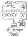
- This single figure represents an exemplary embodiment of the control circuit for a graphics machine according to the invention.
- the improvement according to the invention which makes it possible to contribute to the construction of a machine with a high level of interactivity, allows partial modifications of the image during an image refreshment, by the modification of only certain image memory plans.
- This memory comprises a certain number of plans. It provides for each pixel a number of bits which is equal to the number of planes and which is greater than the number of bits necessary for the addressing of the color table memory.
- the control circuit for a graphics machine shown in the figure includes an image memory 1, the content of which is supplied to each image calculation by the assembly 10 including the computer and the conventional graphics resources.
- Each image point is characterized by an aspect word having a number of bits at most equal to the number n of planes in the image memory, ie 16 in the example above.
- the output bus of this memory is a bus of n bits, that is to say 16 bits.
- This bus is connected to an input of a plane selector circuit 3.
- Another input of circuit 3 receives a command word from a configuration command register 2, to select from the aspect word a determined group of bits by the user.
- This configuration command register 2 is loaded via the resources of the graphics system (set 10).
- the output of the plane selector circuit 3 is connected by an n-bit bus to an addressing input of a color transcoding table memory 4 which supplies a color word for each image point.
- the number ni is less than n, which means that the appearance of a point on the screen cannot be defined at any given time by more than n 'bits.
- the selector circuit 3 therefore selects, for each point, from among the 16 bits supplied by the 16 planes of the image memory, at most 8 appearance bits and it transmits them for the addressing of the table memory 4.
- Each of the 2 8 colored words stored at an address of the table memory 4 can consist of 3 words of 8 data bits respectively associated with the three primary colors R, G, B. These 3 words, read at the address provided by the selector circuit 3 after selection of the planes of the image memory, are respectively applied to three digital-analog converters (DAC), 51, 52, 53 whose outputs provide the analog signals R, G, B controlling the red beams , green and blue of a trichrome cathode ray tube in a projection device 6.
- DAC digital-analog converters
- the circuit 3 is controlled by control words of n.n 'bits, that is to say 1 control word of n bits applied to each of the n' selectors.
- Each selector then comprises n logical AND gates each receiving a bit of the word of n bits from the image memory 1, and a bit of the control word with n bit; the n AND gates of a selector have their outputs connected to a logic circuit OR with n 'inputs and one output, which provides a bit of the address of the table memory 4.
- an elementary image can be memorized by a "logical plane" of the image memory made up of a subset of the planes of this memory, and the 16 planes of the image memory can per put to define several logical planes, each one being associated with a subset of the image forming an elementary image.
- the processing of these different elementary images by the graphics processor of the display system can be carried out independently, both for their calculation and for their refreshment.
- the control circuit according to the invention allows the user to view, on request, one of these different elementary images or else any combination of these images by means of a command issued by the command register. configuration 2. This arrangement allows the resources available to be adapted to the user's needs.
- Essential elements of the relief are stored in a subset of the planes of this first "logical plane", and additional elements of the relief are stored in another subset of the planes of this first "logical plane".
- the circuit described above constitutes a first improvement which can be combined with another improvement relating to the color tables.
- a color palette larger than the capacity of the color transcoding table memory 4, which capacity is 28 colors in the example above
- the user replaces, as desired, the content of table memory 4 with the content of one of the buffers 71 to 74 of this set 7.
- the transfer of one of these 4 buffers 71 to 74 in the memory 4 is controlled by two bits associated with the table used for the synthesis of the image and supplied by the computer unit 10 and graphic resources.
- the corresponding transfer control means have not been shown in the figure. They are described in detail in French patent application No.
- this second improvement offers an additional possibility to modify the appearance of a point of the screen from one scanning period to the next without modifying the content of the image memory, by the simple command of the transfer of a table of a buffer memory 71, ..., 74 in the table memory 4.
- this control circuit provided with the first or the combination of the first and the second improvement in a graphic machine opens up great possibilities of interaction between the machine and the user, by simple commands which do not occupy calculation time in the set 10 computer and graphic resources controlling the machine.
Landscapes
- Engineering & Computer Science (AREA)
- Physics & Mathematics (AREA)
- Computer Hardware Design (AREA)
- General Physics & Mathematics (AREA)
- Theoretical Computer Science (AREA)
- Controls And Circuits For Display Device (AREA)
Claims (4)
Applications Claiming Priority (2)
| Application Number | Priority Date | Filing Date | Title |
|---|---|---|---|
| FR8507149A FR2581779B1 (fr) | 1985-05-10 | 1985-05-10 | Circuit de commande pour machine graphique et utilisation d'un tel circuit dans une machine graphique interactive |
| FR8507149 | 1985-05-10 |
Publications (2)
| Publication Number | Publication Date |
|---|---|
| EP0201428A1 EP0201428A1 (de) | 1986-12-17 |
| EP0201428B1 true EP0201428B1 (de) | 1990-09-05 |
Family
ID=9319172
Family Applications (1)
| Application Number | Title | Priority Date | Filing Date |
|---|---|---|---|
| EP19860400980 Expired - Lifetime EP0201428B1 (de) | 1985-05-10 | 1986-05-06 | Steuerungsschaltung für eine graphische Maschine und Verwendung dieser Schaltung in einer interaktiven graphischen Maschine |
Country Status (3)
| Country | Link |
|---|---|
| EP (1) | EP0201428B1 (de) |
| DE (1) | DE3673864D1 (de) |
| FR (1) | FR2581779B1 (de) |
Families Citing this family (2)
| Publication number | Priority date | Publication date | Assignee | Title |
|---|---|---|---|---|
| JPH068993B2 (ja) * | 1987-02-05 | 1994-02-02 | 株式会社ナムコ | 映像表示装置 |
| JP2612475B2 (ja) * | 1988-06-24 | 1997-05-21 | 日本航空電子工業株式会社 | カラー表示パネルの表示制御装置 |
Family Cites Families (2)
| Publication number | Priority date | Publication date | Assignee | Title |
|---|---|---|---|---|
| GB2032740A (en) * | 1978-10-16 | 1980-05-08 | Tektronix Inc | Programmable color mapping |
| NL8101339A (nl) * | 1981-03-19 | 1982-10-18 | Philips Nv | Inrichting voor het afbeelden van digitale informatie met selektiemogelijkheid van beeldpagina's en/of resolutie uitbreiding. |
-
1985
- 1985-05-10 FR FR8507149A patent/FR2581779B1/fr not_active Expired
-
1986
- 1986-05-06 DE DE8686400980T patent/DE3673864D1/de not_active Expired - Fee Related
- 1986-05-06 EP EP19860400980 patent/EP0201428B1/de not_active Expired - Lifetime
Also Published As
| Publication number | Publication date |
|---|---|
| DE3673864D1 (de) | 1990-10-11 |
| FR2581779A1 (fr) | 1986-11-14 |
| FR2581779B1 (fr) | 1987-06-12 |
| EP0201428A1 (de) | 1986-12-17 |
Similar Documents
| Publication | Publication Date | Title |
|---|---|---|
| US4484187A (en) | Video overlay system having interactive color addressing | |
| US4639771A (en) | Image processing system | |
| US4951229A (en) | Apparatus and method for managing multiple images in a graphic display system | |
| US5038300A (en) | Extendable-size color look-up table for computer graphics systems | |
| FR2604019A1 (fr) | Dispositif d'affichage video couleur pour systeme d'ordinateur, et procede de conversion de signaux video couleur a cet effet | |
| US4262302A (en) | Video display processor having an integral composite video generator | |
| FR2599873A1 (fr) | Systeme d'affichage video | |
| JPS6025794B2 (ja) | カラ−図形表示装置 | |
| FR2589601A1 (fr) | Organisation de memoire notamment pour systeme d'affichage a ordinateur et procede d'organisation | |
| JPH0420191B2 (de) | ||
| JPH04267425A (ja) | オーバレイ及びアンダレイの選択的制御装置 | |
| US4935730A (en) | Display apparatus | |
| EP0422729B1 (de) | Empfänger für Fernsehsignale | |
| US4286320A (en) | Digital computing system having auto-incrementing memory | |
| JPS61132995A (ja) | 電子カラー信号発生器 | |
| EP0201428B1 (de) | Steuerungsschaltung für eine graphische Maschine und Verwendung dieser Schaltung in einer interaktiven graphischen Maschine | |
| JPH02277377A (ja) | パターン縮小方法およびその方法を実施する装置 | |
| EP0197846B1 (de) | Farbvideosignalsteuerschaltung für ein hochauflösendes Anzeigesystem und diese Schaltung umfassendes Anzeigesystem | |
| EP0161175B1 (de) | Einrichtung zum Modifizieren des Aspektes der Bildpunkte auf einem Bildschirm eines graphischen Anzeigegerätes | |
| FR2631474A1 (fr) | Circuit et procede pour commander la presentation d'une information de couleurs a un dispositif d'affichage d'un systeme informatique | |
| BE1001063A3 (fr) | Systeme d'affichage numerique a balayage de trame. | |
| JPS638476B2 (de) | ||
| USRE31977E (en) | Digital computing system having auto-incrementing memory | |
| EP0149399B1 (de) | Steuervorrichtung für graphische Darstellung | |
| US5745104A (en) | Palette control circuit |
Legal Events
| Date | Code | Title | Description |
|---|---|---|---|
| PUAI | Public reference made under article 153(3) epc to a published international application that has entered the european phase |
Free format text: ORIGINAL CODE: 0009012 |
|
| AK | Designated contracting states |
Kind code of ref document: A1 Designated state(s): DE GB IT NL |
|
| PUAB | Information related to the publication of an a document modified or deleted |
Free format text: ORIGINAL CODE: 0009199EPPU |
|
| PUAF | Information related to the publication of a search report (a3 document) modified or deleted |
Free format text: ORIGINAL CODE: 0009199SEPU |
|
| R17D | Deferred search report published (corrected) |
Effective date: 19861217 |
|
| RA1 | Application published (corrected) |
Date of ref document: 19861217 Kind code of ref document: A1 |
|
| 17P | Request for examination filed |
Effective date: 19870401 |
|
| 17Q | First examination report despatched |
Effective date: 19890220 |
|
| RAP1 | Party data changed (applicant data changed or rights of an application transferred) |
Owner name: THOMSON-CSF |
|
| GRAA | (expected) grant |
Free format text: ORIGINAL CODE: 0009210 |
|
| AK | Designated contracting states |
Kind code of ref document: B1 Designated state(s): DE GB IT NL |
|
| ITF | It: translation for a ep patent filed | ||
| GBT | Gb: translation of ep patent filed (gb section 77(6)(a)/1977) | ||
| REF | Corresponds to: |
Ref document number: 3673864 Country of ref document: DE Date of ref document: 19901011 |
|
| PGFP | Annual fee paid to national office [announced via postgrant information from national office to epo] |
Ref country code: DE Payment date: 19910419 Year of fee payment: 6 |
|
| PGFP | Annual fee paid to national office [announced via postgrant information from national office to epo] |
Ref country code: GB Payment date: 19910423 Year of fee payment: 6 |
|
| ITTA | It: last paid annual fee | ||
| PGFP | Annual fee paid to national office [announced via postgrant information from national office to epo] |
Ref country code: NL Payment date: 19910531 Year of fee payment: 6 |
|
| PLBE | No opposition filed within time limit |
Free format text: ORIGINAL CODE: 0009261 |
|
| STAA | Information on the status of an ep patent application or granted ep patent |
Free format text: STATUS: NO OPPOSITION FILED WITHIN TIME LIMIT |
|
| 26N | No opposition filed | ||
| PG25 | Lapsed in a contracting state [announced via postgrant information from national office to epo] |
Ref country code: GB Effective date: 19920506 |
|
| PG25 | Lapsed in a contracting state [announced via postgrant information from national office to epo] |
Ref country code: NL Effective date: 19921201 |
|
| GBPC | Gb: european patent ceased through non-payment of renewal fee |
Effective date: 19920506 |
|
| NLV4 | Nl: lapsed or anulled due to non-payment of the annual fee | ||
| PG25 | Lapsed in a contracting state [announced via postgrant information from national office to epo] |
Ref country code: DE Effective date: 19930202 |
|
| PG25 | Lapsed in a contracting state [announced via postgrant information from national office to epo] |
Ref country code: IT Free format text: LAPSE BECAUSE OF NON-PAYMENT OF DUE FEES;WARNING: LAPSES OF ITALIAN PATENTS WITH EFFECTIVE DATE BEFORE 2007 MAY HAVE OCCURRED AT ANY TIME BEFORE 2007. THE CORRECT EFFECTIVE DATE MAY BE DIFFERENT FROM THE ONE RECORDED. Effective date: 20050506 |