EP0201959A1 - Vorrichtung zur gleichzeitigen Umhüllung von mehreren elektronischen Bauteilen - Google Patents
Vorrichtung zur gleichzeitigen Umhüllung von mehreren elektronischen Bauteilen Download PDFInfo
- Publication number
- EP0201959A1 EP0201959A1 EP86200737A EP86200737A EP0201959A1 EP 0201959 A1 EP0201959 A1 EP 0201959A1 EP 86200737 A EP86200737 A EP 86200737A EP 86200737 A EP86200737 A EP 86200737A EP 0201959 A1 EP0201959 A1 EP 0201959A1
- Authority
- EP
- European Patent Office
- Prior art keywords
- mould
- plungers
- plunger
- strip
- pellets
- Prior art date
- Legal status (The legal status is an assumption and is not a legal conclusion. Google has not performed a legal analysis and makes no representation as to the accuracy of the status listed.)
- Withdrawn
Links
- 238000010438 heat treatment Methods 0.000 claims abstract description 7
- 238000002347 injection Methods 0.000 claims abstract description 5
- 239000007924 injection Substances 0.000 claims abstract description 5
- 239000004020 conductor Substances 0.000 claims abstract description 4
- 239000008188 pellet Substances 0.000 claims description 27
- 239000000463 material Substances 0.000 claims description 10
- 229920003023 plastic Polymers 0.000 claims description 10
- 239000004033 plastic Substances 0.000 claims description 10
- 208000015943 Coeliac disease Diseases 0.000 claims description 4
- 238000005538 encapsulation Methods 0.000 claims description 4
- PCHJSUWPFVWCPO-UHFFFAOYSA-N gold Chemical compound [Au] PCHJSUWPFVWCPO-UHFFFAOYSA-N 0.000 description 2
- 239000010931 gold Substances 0.000 description 2
- 229910052737 gold Inorganic materials 0.000 description 2
- 239000007788 liquid Substances 0.000 description 1
- 239000006187 pill Substances 0.000 description 1
Images

Classifications
-
- B—PERFORMING OPERATIONS; TRANSPORTING
- B29—WORKING OF PLASTICS; WORKING OF SUBSTANCES IN A PLASTIC STATE IN GENERAL
- B29C—SHAPING OR JOINING OF PLASTICS; SHAPING OF MATERIAL IN A PLASTIC STATE, NOT OTHERWISE PROVIDED FOR; AFTER-TREATMENT OF THE SHAPED PRODUCTS, e.g. REPAIRING
- B29C45/00—Injection moulding, i.e. forcing the required volume of moulding material through a nozzle into a closed mould; Apparatus therefor
- B29C45/03—Injection moulding apparatus
- B29C45/13—Injection moulding apparatus using two or more injection units co-operating with a single mould
-
- B—PERFORMING OPERATIONS; TRANSPORTING
- B29—WORKING OF PLASTICS; WORKING OF SUBSTANCES IN A PLASTIC STATE IN GENERAL
- B29C—SHAPING OR JOINING OF PLASTICS; SHAPING OF MATERIAL IN A PLASTIC STATE, NOT OTHERWISE PROVIDED FOR; AFTER-TREATMENT OF THE SHAPED PRODUCTS, e.g. REPAIRING
- B29C45/00—Injection moulding, i.e. forcing the required volume of moulding material through a nozzle into a closed mould; Apparatus therefor
- B29C45/02—Transfer moulding, i.e. transferring the required volume of moulding material by a plunger from a "shot" cavity into a mould cavity
-
- B—PERFORMING OPERATIONS; TRANSPORTING
- B29—WORKING OF PLASTICS; WORKING OF SUBSTANCES IN A PLASTIC STATE IN GENERAL
- B29C—SHAPING OR JOINING OF PLASTICS; SHAPING OF MATERIAL IN A PLASTIC STATE, NOT OTHERWISE PROVIDED FOR; AFTER-TREATMENT OF THE SHAPED PRODUCTS, e.g. REPAIRING
- B29C45/00—Injection moulding, i.e. forcing the required volume of moulding material through a nozzle into a closed mould; Apparatus therefor
- B29C45/14—Injection moulding, i.e. forcing the required volume of moulding material through a nozzle into a closed mould; Apparatus therefor incorporating preformed parts or layers, e.g. injection moulding around inserts or for coating articles
- B29C45/14639—Injection moulding, i.e. forcing the required volume of moulding material through a nozzle into a closed mould; Apparatus therefor incorporating preformed parts or layers, e.g. injection moulding around inserts or for coating articles for obtaining an insulating effect, e.g. for electrical components
- B29C45/14655—Injection moulding, i.e. forcing the required volume of moulding material through a nozzle into a closed mould; Apparatus therefor incorporating preformed parts or layers, e.g. injection moulding around inserts or for coating articles for obtaining an insulating effect, e.g. for electrical components connected to or mounted on a carrier, e.g. lead frame
-
- B—PERFORMING OPERATIONS; TRANSPORTING
- B29—WORKING OF PLASTICS; WORKING OF SUBSTANCES IN A PLASTIC STATE IN GENERAL
- B29C—SHAPING OR JOINING OF PLASTICS; SHAPING OF MATERIAL IN A PLASTIC STATE, NOT OTHERWISE PROVIDED FOR; AFTER-TREATMENT OF THE SHAPED PRODUCTS, e.g. REPAIRING
- B29C45/00—Injection moulding, i.e. forcing the required volume of moulding material through a nozzle into a closed mould; Apparatus therefor
- B29C45/17—Component parts, details or accessories; Auxiliary operations
- B29C45/46—Means for plasticising or homogenising the moulding material or forcing it into the mould
- B29C45/462—Injection of preformed charges of material
-
- B—PERFORMING OPERATIONS; TRANSPORTING
- B29—WORKING OF PLASTICS; WORKING OF SUBSTANCES IN A PLASTIC STATE IN GENERAL
- B29C—SHAPING OR JOINING OF PLASTICS; SHAPING OF MATERIAL IN A PLASTIC STATE, NOT OTHERWISE PROVIDED FOR; AFTER-TREATMENT OF THE SHAPED PRODUCTS, e.g. REPAIRING
- B29C45/00—Injection moulding, i.e. forcing the required volume of moulding material through a nozzle into a closed mould; Apparatus therefor
- B29C45/17—Component parts, details or accessories; Auxiliary operations
- B29C45/76—Measuring, controlling or regulating
Definitions
- the invention relates to an apparatus for simultaneously encapsulating a plurality of electronic components which are fastened by their connection points to the conductors of a strip which is subsequently to be divided into separate parts, said apparatus consisting of a heatable mould comprising a top half and a bottom half and being adapted to receive at least one strip containing one or more electronic components, and further consisting of an injection unit which is placed along the long side of the mould and has a plurality of hydraulically controllable plungers adapted to be moved towards and away from the mould cavity sprues leading into the side wall of the mould, a number of chambers for receiving pellets of the plastics material used for the encapsulation, the number of chambers being equal to the number of plungers and said chambers being situated between the plungers in their retracted position and plunger cavities, corresponding to the diameter of the plungers, in the mould.
- Electronic components particularly integrated circuits, are generally soldered to the conductors of the strip with the aid of particularly thin gold wires.
- the encapsulation with plastics material must be effected in such a manner that the connections are not broken, that is to say the gold wires must not be broken or detached from the soldered joint by the liquid plastics material flowirig at high speed.
- a hydraulic pressure cylinder presses the liquefied plastics material under pressure, and consequently at varying speed, into the mould cavity, which may give rise to the breaking of connections.
- the invention seeks to provide an apparatus with which this shortcoming does not occur.
- each plunger is mounted for sliding in a carrier frame which in turn is adapted to be moved away from and towards the mould by means of a mechanism which is adapted to move the carrier frame at a controlled speed; that each plunger is connected to a pressure means adapted to exert a constant pressure on the plunger; that each plunger has a heating element, and that each plunger carries a signal means and that all the signal means of all the plungers are connected to the operating circuit of the driving mechanism, in such a manner that on the softening of the pellets subjected to pressure and heated by the plungers the driving mechanism moves the frame towards the mould as soon as all the signal means have operated.
- the driving mechanism used may be a hydraulic driving mechanism, such as hydraulic cylinders, because when a controlled volume flow is provided the movement of the piston in the cylinder is possible at for example a controlled (optionally constant) speed.
- the plungers may each be coupled to a hydraulic operating cylinder. These cylinders are connected to a hydraulic circuit whose pressure can be brought to two preadjustable levels by means of hydraulic pressure controllers, this circuit including if necessary an accumulator and containing a gaseous medium under pressure. These controllers then supply the force for applying the heated plungers against the pellets and thus ensure the application of pressure.
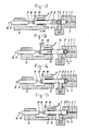
- the drawings show a mould comprising a top half 1 and a bottom half 2, between which are formed a row of mould cavities 3 with sprues 4 and a plunger cavity 5.
- a horizontally movable carrier frame which is coupled to two hydraulic cylinders 10.
- This carrier frame carries a number of plungers 11, which at 12 are guided for sliding in the frame and which are provided with a head 13 whose diameter is such that this head will fit accuraterly into the plunger cavity 5 of the mould.
- Each head is provided with a heating element 14.
- Each plunger carries a contact 19 cooperating with a counter-contact 20.
- Figure 2 shows the starting position in which the mould 1, 2 is closed and a pellet 8 is disposed in front of each opening 5.
- the carrier frame 9 is now moved with the aid of the cylinders 10 from the position shown in Figure 2 to the position shown in Figure 3, in which the heads 13 of the plungers 11 have entered the plunger cavities 5 and have thus pushed the pellets 8 in front of them and pressed them into the plunger cavity; as a consequence of this movement the plungers have been slightly pressed back, that is to say the hydraulic circuit 15, 16 has been slightly tensioned so that the distance indicated at 21 in Figure 3 is formed between the contacts 19 and 20.
- the carrier frame moves all the plungers simultaneously at a predetermined controllable speed, the filling is effected in the required careful manner.
- the stroke of the cylinders 10 can be accurately limited, because before the carrier frame is moved for the purpose of filling the mould cavities, each plunger has already been brought into a position which takes into account any slightly different dimensions of the pellets in relation to one another.
- any other mechanism which can ensure a controlled speed may be used, for example a threaded spindle mechanism driven by an electric motor.
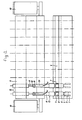
- the strip 6 is movable from the position shown to the right in Figure 6, as indicated by the arrow 26.
- the recesses 21 are then filled one by one with pellets.
Landscapes
- Engineering & Computer Science (AREA)
- Manufacturing & Machinery (AREA)
- Mechanical Engineering (AREA)
- Encapsulation Of And Coatings For Semiconductor Or Solid State Devices (AREA)
- Injection Moulding Of Plastics Or The Like (AREA)
Applications Claiming Priority (2)
| Application Number | Priority Date | Filing Date | Title |
|---|---|---|---|
| NL8501393A NL8501393A (nl) | 1985-05-14 | 1985-05-14 | Inrichting voor het tegelijkertijd omhullen van een aantal elektronische componenten. |
| NL8501393 | 1985-05-14 |
Publications (1)
| Publication Number | Publication Date |
|---|---|
| EP0201959A1 true EP0201959A1 (de) | 1986-11-20 |
Family
ID=19845987
Family Applications (1)
| Application Number | Title | Priority Date | Filing Date |
|---|---|---|---|
| EP86200737A Withdrawn EP0201959A1 (de) | 1985-05-14 | 1986-04-28 | Vorrichtung zur gleichzeitigen Umhüllung von mehreren elektronischen Bauteilen |
Country Status (4)
| Country | Link |
|---|---|
| US (1) | US4752198A (de) |
| EP (1) | EP0201959A1 (de) |
| JP (1) | JPS6284524A (de) |
| NL (1) | NL8501393A (de) |
Cited By (6)
| Publication number | Priority date | Publication date | Assignee | Title |
|---|---|---|---|---|
| EP0370564A1 (de) * | 1988-11-22 | 1990-05-30 | Ireneus Johannes Theodores Maria Pas | Verfahren zum Verpacken einer bestimmten Menge hitzehärtbaren Harzes, die zum Einschliessen von Komponenten bestimmt ist, durch dieses Verfahren erhaltene Verpackung, Verfahren zum Betrieb einer Form und Form zur Durchführung dieses Verfahrens |
| EP0458577A1 (de) * | 1990-05-21 | 1991-11-27 | Nec Corporation | Herstellungsverfahren für eine in Harz eingebettete Halbleitervorrichtung |
| NL9100339A (nl) * | 1991-02-26 | 1992-09-16 | Boschman Tech Bv | Inrichting voor het omhullen van elektronische onderdelen. |
| WO1996012603A1 (en) * | 1994-10-19 | 1996-05-02 | Fico B.V. | Module for encapsulating electronic components and coupling in a plunger rod |
| WO1997005997A1 (de) * | 1995-08-09 | 1997-02-20 | Maschinenfabrik Lauffer Gmbh & Co. Kg | Hydraulische presse zur umhüllung von halbleiterbauelementen |
| WO2007054315A1 (en) * | 2005-11-10 | 2007-05-18 | Airbus Deutschland Gmbh | Tool, arrangement, and method for manufacturing a component, component |
Families Citing this family (8)
| Publication number | Priority date | Publication date | Assignee | Title |
|---|---|---|---|---|
| US4812114A (en) * | 1987-09-30 | 1989-03-14 | Texas Instruments Incorporated | New IC molding process |
| US4915607A (en) * | 1987-09-30 | 1990-04-10 | Texas Instruments Incorporated | Lead frame assembly for an integrated circuit molding system |
| DE4227692C2 (de) * | 1992-06-11 | 1996-05-23 | Lauffer Maschf | Spritzpresse mit mehreren Spritzkolben |
| NL9202253A (nl) * | 1992-12-23 | 1994-07-18 | Asm Fico Tooling | Stelsel voor het gedoseerd opvoeren en uitselecteren van cilindervormige pellets voor omhulinrichtingen voor leadframes. |
| US8029720B2 (en) * | 2005-11-25 | 2011-10-04 | Dai-Ichi Seiko Co., Ltd. | Resin sealing apparatus and resin sealing method |
| DE102007001756B4 (de) * | 2007-01-11 | 2008-12-18 | Itw Automotive Products Gmbh & Co. Kg | Verfahren und Spritzgussform zum Spritzgießen von hohlen Formteilen aus Kunststoff |
| US9259290B2 (en) * | 2009-06-08 | 2016-02-16 | MRI Interventions, Inc. | MRI-guided surgical systems with proximity alerts |
| WO2010148083A2 (en) | 2009-06-16 | 2010-12-23 | Surgivision, Inc. | Mri-guided devices and mri-guided interventional systems that can track and generate dynamic visualizations of the devices in near real time |
Citations (9)
| Publication number | Priority date | Publication date | Assignee | Title |
|---|---|---|---|---|
| US2500546A (en) * | 1946-03-20 | 1950-03-14 | Whitney Blake Co | Apparatus for molding terminals on electric conductors |
| US3458931A (en) * | 1963-09-16 | 1969-08-05 | Western Electric Co | Method for molding terminals in workpieces |
| GB1164301A (en) * | 1965-09-13 | 1969-09-17 | Tapser S L | Improvements in Injection Moulding. |
| US3571856A (en) * | 1969-05-14 | 1971-03-23 | Bischoff Chemical Corp | Apparatus for simultaneously opening valves for plurality of injection nozzles |
| DE3032814A1 (de) * | 1980-08-30 | 1982-04-22 | Kunststoff-Maschinen-Handelsgesellschaft mbH, 4990 Lübbecke | Vorrichtung zum spritzpressen haertbarer formmassen |
| US4347211A (en) * | 1979-08-24 | 1982-08-31 | Kazuo Bandoh | Process and apparatus for molding plastics |
| EP0070320A1 (de) * | 1981-01-26 | 1983-01-26 | Dai-Ichi Seiko Co. Ltd. | Apparat zum versiegeln und dichten |
| EP0101630A1 (de) * | 1982-08-19 | 1984-02-29 | Arbo Handels- En Ontwikkelingsmij B.V. | Verfahren und System zum Einkapseln elektronischer Bauteile in Kunststoff |
| US4511317A (en) * | 1981-12-07 | 1985-04-16 | Kazuo Bandoh | Apparatus for enclosing semiconductors with resin by molding |
Family Cites Families (11)
| Publication number | Priority date | Publication date | Assignee | Title |
|---|---|---|---|---|
| US2333056A (en) * | 1940-12-16 | 1943-10-26 | Hydraulic Dev Corp Inc | Turret type injection press |
| US2779059A (en) * | 1952-08-15 | 1957-01-29 | Kruft Corp | Apparatus for controlled deposition of material |
| US3095785A (en) * | 1960-08-18 | 1963-07-02 | Specialties Inc | Positioning device |
| US3380117A (en) * | 1966-02-07 | 1968-04-30 | Gluck William | Automatic molding machine |
| JPS5156868A (ja) * | 1974-11-13 | 1976-05-18 | Kobe Steel Ltd | Shashutsuseikeiki |
| US4316145A (en) * | 1976-10-01 | 1982-02-16 | Electro-Mechanical Products | Fluid pressure actuator with proximity position sensor |
| US4161386A (en) * | 1977-12-19 | 1979-07-17 | Incoe Corporation | Nozzle for injection molding machines |
| DE2945895C2 (de) * | 1979-11-14 | 1986-06-05 | Festo-Maschinenfabrik Gottlieb Stoll, 7300 Esslingen | Magnetischer Stellungsgeber für hydrauliche oder pneumatische Arbeitszylinder |
| DE3243632A1 (de) * | 1982-11-25 | 1984-05-30 | Flewu AG, 9000 St. Gallen | Verfahren und vorrichtung zur sinterung insbesondere unterschiedlicher formlinge aus insbesondere verschiedenartigen schaeumbaren kunststoffen |
| JPS60125616A (ja) * | 1983-10-19 | 1985-07-04 | Daiichi Seikou Kk | 樹脂封止用金型 |
| US4563149A (en) * | 1984-04-20 | 1986-01-07 | Landis Plastics Inc. | Injection molding apparatus |
-
1985
- 1985-05-14 NL NL8501393A patent/NL8501393A/nl not_active Application Discontinuation
-
1986
- 1986-04-28 EP EP86200737A patent/EP0201959A1/de not_active Withdrawn
- 1986-05-14 US US06/863,024 patent/US4752198A/en not_active Expired - Fee Related
- 1986-05-14 JP JP61112429A patent/JPS6284524A/ja active Pending
Patent Citations (9)
| Publication number | Priority date | Publication date | Assignee | Title |
|---|---|---|---|---|
| US2500546A (en) * | 1946-03-20 | 1950-03-14 | Whitney Blake Co | Apparatus for molding terminals on electric conductors |
| US3458931A (en) * | 1963-09-16 | 1969-08-05 | Western Electric Co | Method for molding terminals in workpieces |
| GB1164301A (en) * | 1965-09-13 | 1969-09-17 | Tapser S L | Improvements in Injection Moulding. |
| US3571856A (en) * | 1969-05-14 | 1971-03-23 | Bischoff Chemical Corp | Apparatus for simultaneously opening valves for plurality of injection nozzles |
| US4347211A (en) * | 1979-08-24 | 1982-08-31 | Kazuo Bandoh | Process and apparatus for molding plastics |
| DE3032814A1 (de) * | 1980-08-30 | 1982-04-22 | Kunststoff-Maschinen-Handelsgesellschaft mbH, 4990 Lübbecke | Vorrichtung zum spritzpressen haertbarer formmassen |
| EP0070320A1 (de) * | 1981-01-26 | 1983-01-26 | Dai-Ichi Seiko Co. Ltd. | Apparat zum versiegeln und dichten |
| US4511317A (en) * | 1981-12-07 | 1985-04-16 | Kazuo Bandoh | Apparatus for enclosing semiconductors with resin by molding |
| EP0101630A1 (de) * | 1982-08-19 | 1984-02-29 | Arbo Handels- En Ontwikkelingsmij B.V. | Verfahren und System zum Einkapseln elektronischer Bauteile in Kunststoff |
Non-Patent Citations (2)
| Title |
|---|
| PATENTS ABSTRACTS OF JAPAN, vol. 8, no. 63, 24th March 1984, 39 E 233, (E-233)[1500]; & JP - A - 58 212 144 (MITSUBISHI DENKI K.K.) 09-12-1983 * |
| PATENTS ABSTRACTS OF JAPAN, vol. 9, no. 159, 4th July 1985, 50 E 326, (E-233)[1500]; & JP - A - 60 37 134 (MITSUBISHI DENKI K.K.) 26-02-1985 * |
Cited By (10)
| Publication number | Priority date | Publication date | Assignee | Title |
|---|---|---|---|---|
| EP0370564A1 (de) * | 1988-11-22 | 1990-05-30 | Ireneus Johannes Theodores Maria Pas | Verfahren zum Verpacken einer bestimmten Menge hitzehärtbaren Harzes, die zum Einschliessen von Komponenten bestimmt ist, durch dieses Verfahren erhaltene Verpackung, Verfahren zum Betrieb einer Form und Form zur Durchführung dieses Verfahrens |
| EP0458577A1 (de) * | 1990-05-21 | 1991-11-27 | Nec Corporation | Herstellungsverfahren für eine in Harz eingebettete Halbleitervorrichtung |
| NL9100339A (nl) * | 1991-02-26 | 1992-09-16 | Boschman Tech Bv | Inrichting voor het omhullen van elektronische onderdelen. |
| US5158780A (en) * | 1991-02-26 | 1992-10-27 | Boschman Technologies B.V. | Device for encapsulating electronic components |
| WO1996012603A1 (en) * | 1994-10-19 | 1996-05-02 | Fico B.V. | Module for encapsulating electronic components and coupling in a plunger rod |
| NL9401738A (nl) * | 1994-10-19 | 1996-06-03 | Fico Bv | Module voor het omhullen van elektronische componenten en koppeling in een plunjerstang. |
| WO1997005997A1 (de) * | 1995-08-09 | 1997-02-20 | Maschinenfabrik Lauffer Gmbh & Co. Kg | Hydraulische presse zur umhüllung von halbleiterbauelementen |
| WO2007054315A1 (en) * | 2005-11-10 | 2007-05-18 | Airbus Deutschland Gmbh | Tool, arrangement, and method for manufacturing a component, component |
| RU2423237C2 (ru) * | 2005-11-10 | 2011-07-10 | Эйрбас Дойчланд Гмбх | Приспособление, система и способ изготовления композитных компонентов |
| US9352517B2 (en) | 2005-11-10 | 2016-05-31 | Airbus Deutschland Gmbh | Resin-transfer-moulding method |
Also Published As
| Publication number | Publication date |
|---|---|
| NL8501393A (nl) | 1986-12-01 |
| US4752198A (en) | 1988-06-21 |
| JPS6284524A (ja) | 1987-04-18 |
Similar Documents
| Publication | Publication Date | Title |
|---|---|---|
| EP0201959A1 (de) | Vorrichtung zur gleichzeitigen Umhüllung von mehreren elektronischen Bauteilen | |
| US5297897A (en) | Single-strip molding apparatus | |
| GB2103534A (en) | Locating inserts during mould filling | |
| US5779958A (en) | Method for packaging electronic device | |
| EP0633111A2 (de) | Einzelband-Formvorrichtung mit beweglichen Formhälften | |
| WO2024014060A1 (ja) | 成形型、樹脂成形装置及び樹脂成形品の製造方法 | |
| US6224810B1 (en) | Method of plastic molding | |
| US3299475A (en) | Metering apparatus for an injection molding machine | |
| JP3131474B2 (ja) | 樹脂モールド方法 | |
| JP3629367B2 (ja) | トランスファー成形装置 | |
| JP3947607B2 (ja) | トランスファモールド装置 | |
| JP3064820B2 (ja) | モールドプレス装置およびモールドプレス方法 | |
| JP3536999B2 (ja) | 樹脂モールド装置 | |
| JPH0393517A (ja) | モールドプレス装置 | |
| JPH0414419A (ja) | トランスファモールド装置 | |
| KR20220140545A (ko) | 몰드 장치 | |
| JP2619670B2 (ja) | 半導体素子の樹脂封止成形方法及び装置 | |
| KR960007278B1 (ko) | 봉입성형용 모울딩 프레스 장치의 금형 | |
| JPH0356341Y2 (de) | ||
| JP3351061B2 (ja) | チップのモールドプレス装置 | |
| JP2630451B2 (ja) | 電子部品の樹脂封止成形方法及び装置 | |
| JPS61125821A (ja) | 樹脂成形装置 | |
| JPH06238701A (ja) | マルチプランジャ型レジンモールド装置 | |
| JPH06143379A (ja) | 樹脂成形機における異物検出方法 | |
| JPS61292926A (ja) | モ−ルド方法およびモ−ルド装置 |
Legal Events
| Date | Code | Title | Description |
|---|---|---|---|
| PUAI | Public reference made under article 153(3) epc to a published international application that has entered the european phase |
Free format text: ORIGINAL CODE: 0009012 |
|
| AK | Designated contracting states |
Kind code of ref document: A1 Designated state(s): DE FR GB IT NL |
|
| 17P | Request for examination filed |
Effective date: 19870512 |
|
| 17Q | First examination report despatched |
Effective date: 19880210 |
|
| STAA | Information on the status of an ep patent application or granted ep patent |
Free format text: STATUS: THE APPLICATION IS DEEMED TO BE WITHDRAWN |
|
| 18D | Application deemed to be withdrawn |
Effective date: 19881103 |
|
| RIN1 | Information on inventor provided before grant (corrected) |
Inventor name: BOSCHMAN, EVERHARDUS HENDRIKUS |