EP0203529A2 - Système et méthode de commande de l'ouverture du papillon en fonction de la position de la pédale d'accélérateur d'un véhicule automobile - Google Patents
Système et méthode de commande de l'ouverture du papillon en fonction de la position de la pédale d'accélérateur d'un véhicule automobile Download PDFInfo
- Publication number
- EP0203529A2 EP0203529A2 EP86106962A EP86106962A EP0203529A2 EP 0203529 A2 EP0203529 A2 EP 0203529A2 EP 86106962 A EP86106962 A EP 86106962A EP 86106962 A EP86106962 A EP 86106962A EP 0203529 A2 EP0203529 A2 EP 0203529A2
- Authority
- EP
- European Patent Office
- Prior art keywords
- throttle valve
- opening angle
- vehicle speed
- change
- accelerator member
- Prior art date
- Legal status (The legal status is an assumption and is not a legal conclusion. Google has not performed a legal analysis and makes no representation as to the accuracy of the status listed.)
- Granted
Links
- 238000000034 method Methods 0.000 title claims abstract description 6
- 238000012888 cubic function Methods 0.000 claims abstract 4
- 230000000994 depressogenic effect Effects 0.000 description 5
- 238000006073 displacement reaction Methods 0.000 description 5
- 230000001133 acceleration Effects 0.000 description 4
- 238000010276 construction Methods 0.000 description 2
- 230000004048 modification Effects 0.000 description 2
- 238000012986 modification Methods 0.000 description 2
- 238000010586 diagram Methods 0.000 description 1
- 230000002349 favourable effect Effects 0.000 description 1
- 230000004044 response Effects 0.000 description 1
Images


Classifications
-
- F—MECHANICAL ENGINEERING; LIGHTING; HEATING; WEAPONS; BLASTING
- F02—COMBUSTION ENGINES; HOT-GAS OR COMBUSTION-PRODUCT ENGINE PLANTS
- F02D—CONTROLLING COMBUSTION ENGINES
- F02D11/00—Arrangements for, or adaptations to, non-automatic engine control initiation means, e.g. operator initiated
- F02D11/06—Arrangements for, or adaptations to, non-automatic engine control initiation means, e.g. operator initiated characterised by non-mechanical control linkages, e.g. fluid control linkages or by control linkages with power drive or assistance
- F02D11/10—Arrangements for, or adaptations to, non-automatic engine control initiation means, e.g. operator initiated characterised by non-mechanical control linkages, e.g. fluid control linkages or by control linkages with power drive or assistance of the electric type
- F02D11/105—Arrangements for, or adaptations to, non-automatic engine control initiation means, e.g. operator initiated characterised by non-mechanical control linkages, e.g. fluid control linkages or by control linkages with power drive or assistance of the electric type characterised by the function converting demand to actuation, e.g. a map indicating relations between an accelerator pedal position and throttle valve opening or target engine torque
-
- F—MECHANICAL ENGINEERING; LIGHTING; HEATING; WEAPONS; BLASTING
- F02—COMBUSTION ENGINES; HOT-GAS OR COMBUSTION-PRODUCT ENGINE PLANTS
- F02D—CONTROLLING COMBUSTION ENGINES
- F02D11/00—Arrangements for, or adaptations to, non-automatic engine control initiation means, e.g. operator initiated
- F02D11/06—Arrangements for, or adaptations to, non-automatic engine control initiation means, e.g. operator initiated characterised by non-mechanical control linkages, e.g. fluid control linkages or by control linkages with power drive or assistance
- F02D11/10—Arrangements for, or adaptations to, non-automatic engine control initiation means, e.g. operator initiated characterised by non-mechanical control linkages, e.g. fluid control linkages or by control linkages with power drive or assistance of the electric type
- F02D2011/101—Arrangements for, or adaptations to, non-automatic engine control initiation means, e.g. operator initiated characterised by non-mechanical control linkages, e.g. fluid control linkages or by control linkages with power drive or assistance of the electric type characterised by the means for actuating the throttles
- F02D2011/102—Arrangements for, or adaptations to, non-automatic engine control initiation means, e.g. operator initiated characterised by non-mechanical control linkages, e.g. fluid control linkages or by control linkages with power drive or assistance of the electric type characterised by the means for actuating the throttles at least one throttle being moved only by an electric actuator
Definitions
- the present invention relates to a system and method for controlling the opening angle of a throttle valve located within a throttle chamber of an intake air passage of an engine according to the position of an accelerator member of an automotive vehicle.
- a system for controlling an opening angle of a throttle valve installed within an engine of a vehicle comprises (a) first means for detecting the operating position of an accelerator member of the vehicle and outputting a signal indicative thereof, (b) second means for determining whether the accelerator member has been operated so as to hold the vehicle speed approximately constant on the basis of the behavior of the signal derived by the first means, and (c) third means for adjusting the opening angle position of the throttle valve to such a degree that the vehicle speed remains approximately constant when the second means determines that the accelerator member has been operated so as to hold the vehicle speed approximately constant and such that the rate of change of the opening angle position of the throttle valve is greater than the rate of change of position of the accelerator member otherwise.
- Fig. 1 shows diagrammatically the whole system according to the present invention.
- the operating position i.e., the angular displacement through which, e.g., a driver depresses an accelerator pedal
- a stroke detecting means such as a potentiometer 16.
- the accelerator pedal 10 is axially supported on a floor panel 12 of the vehicle and is biased in the counterclockwise direction as viewed in Fig. 1 by means of a return spring 14.
- a throttle valve 18 is installed within a throttle chamber of an intake air passage of an engine and is not mechanically linked with the accelerator pedal 10.
- a rotational axis 22 of the throttle valve 18 is biased toward the fully-closed position of the throttle valve 18 by means of a return spring 26 via a lever 24.
- the angular displacement of the throttle valve 18 is controlled by means of a motor 28 and the angular position of the throttle valve 18 is detected by means of a potentiometer 30.
- the output signals of the potentiometers 30, 16 are sent to a processing circuit 34 via A/D (analog-to-digital) converters 31, 32.
- the processing circuit 34 derives a control signal for controlling the throttle valve.
- This control signal is sent to a motor drive circuit 38 via a D/A (digital-to-analog) converter 36.
- the motor drive circuit 38 activates and controls the rotation of the motor 28 so that the throttle valve 18 is opened or closed according to actuation of the accelerator pedal 10.
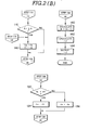
- the processing circuit 34 comprises a microcomputer. The operation of the first preferred embodiment will be described with reference to Figs. 2(A) and 2(B).
- the processing routine shown in Figs. 2(A) and 2(B) is activated at a predetermined period by means of an operating system (not shown) usually stored in a ROM (Read Only Memory) which is part of the microcomputer.
- a step 100 the depression l 1 (angular position) of the accelerator pedal recorded in the last execution cycle of this routine is stored as a two-times previous depression value l 2 .
- a step 102 the depression value l 0 of the accelerator pedal sampled in the execution cycle immediately prior to the current routine cycle is stored as a previous depression value l 1.
- a step 106 shown in Fig. 2(A) the current depression of the accelerator pedal 10 is sampled and recorded as the current depression value l 0 .
- a step 108 the current change in position L 0 of the accelerator pedal 10 from the previous to the current routine cycle is calculated by subtracting the previous depression value l 1 from the current depression value l 0 .
- the processing circuit 34 determines whether the accelerator pedal 10 has been consistently actuated in the depression direction over the last two execution cycles on the basis of these change values L o and L 1 . In other words, if both change values L 0 , L 1 are positive when checked in steps 112, 114, respectively, the processing circuit 34 recognizes that the accelerator pedal 10 has been depressed for the last two execution cycles, and control passes to a step 118. Conversely, the processing circuit 34 determines that the accelerator pedal 10 is being consistently released when the values L 0 , L 1 are both negative when checked in the steps 112 and 114, and in this case, control passes to a step 146, as will be explained later.
- the offset L of the accelerator pedal 10 from a reference position too is calculated by subtracting the reference position value l 00 from the current position value l 0 .
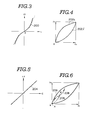
- the desired change in the opening angle of the throttle valve corresponding to the offset value L is derived from a characteristic curve 200, which is substantially a cubic curve, shown in Fig. 3 (the curve shown in Fig. 3 is prepared in the form of a map lattice and therefore a table look-up technique is used).
- a characteristic curve 200 which is substantially a cubic curve, shown in Fig. 3 (the curve shown in Fig. 3 is prepared in the form of a map lattice and therefore a table look-up technique is used).
- steps 124 and 126 upper and lower limit values ⁇ h and ⁇ l of the target value ⁇ 0 for the opening angle of the throttle valve are calculated from the characteristic curves 202h, 202( shown in Fig. 4.
- the target value ⁇ 0 of the opening angle of the throttle valve is compared with these limit values ⁇ h , e in respective steps 128, 130.
- the target value ⁇ 0 of the throttle valve opening angle exceeds the upper limit value ⁇ h (positive result in the step 128) or if the target value ⁇ 0 is below the lower limit value ⁇ l , the target value ⁇ 0 of the opening angle of the throttle valve is forcibly set to the closer of these values ⁇ h , ⁇ l in a step 132 or 134. If the target value ⁇ 0 of the throttle valve lies between these values ⁇ h and ⁇ l , the value ⁇ 0 remains unchanged in a step 136.
- the actual opening angle ⁇ r of the throttle valve 18 is read in a step 138.
- the deviation a of the actual opening angle 8 from the target value ⁇ 0 is calculated in a step 140.
- a control value for the opening angle ⁇ is calculated from a characteristic curve 204 shown in Fig. 5 (The characteristic curve 204 is prepared in the form of a map grid.).
- the calculated control value for the opening angle ⁇ is sent to the motor drive circuit 38 via the D/A converter 36 in a step 144.
- the opening angle of the throttle valve 18 is controlled in a direction which accords with the target opening angle ⁇ 0 .
- the processing circuit 34 recognizes that the vehicle is to be accelerated or decelerated and the vehicle driver does not intend to hold the vehicle speed constant. Therefore, the throttle valve 18 is opened or closed so that the vehicle is accelerated or decelerated.
- the throttle valve is opened in accordance with the characteristic curve 206 shown in Fig. 6 and the vehicle accelerates.
- the operation of the preferred embodiment will be described in cases where the driver works the accelerator pedal 10 so as to hold the vehicle speed constant.
- the processing circuit 24 recognizes that the driver works the accelerator pedal 10 so as to hold the vehicle speed constant in cases where the accelerator pedal 10 is first depressed, and then held in place or released (negative result in the step 112 and positive result in the step 116), and in cases where the accelerator pedal 10 is first held in place or released and then depressed (positive result in the step 112 and negative result in the step 114).
- the current depression value 10) is taken as the reference depression value l 00 (step 146). It is noted that, also in the step 146, a target value ⁇ 0 of the opening angle of the throttle valve derived in the previous routine cycle is stored as a prior target value ⁇ 1 (6 1 ⁇ - ⁇ 0 ) . Therefore, since the offset value L will be calculated to be zero in step 118, the position of the throttle valve 18 will not be adjusted.
- the throttle valve 18 is controlled in accordance with the operation of the accelerator pedal 10.
- the characteristic curve 200 is substantially a cubic curve as appreciated from Fig. 3 and hence the rate of increase or decrease in the opening angle is small in the region of small positive or negative offsets L and the rate of increase or decrease in the opening angle increases as the absolute value of offset L increases.
- the characteristic curve may be approximated by three straight lines denoted by the dotted lines in Fig. 3.
- the throttle value 18 will open wide or shut down quickly so that a sufficient acceleration or deceleration of the vehicle can be achieved.
- the throttle valve 18 will subsequently be controlled to open or close in accordance with the characteristic curve 208 from the stable operating point B. Vehicle acceleration will be sufficient and, on the other hand, the vehicle speed can easily be held constant.
- Fig. 7 shows an operational flowchart for a second preferred embodiment.
- the construction of the second preferred embodiment is substantially the same as the first preferred embodiment shown in Fig. 1.
- a vehicle speed sensor 40 enclosed in dotted lines in Fig. 1 is added to the apparatus in the second embodiment.
- FIG. 7 illustrates a modification to sequence of steps 146-118. Since the steps other than steps 148 through 154 in Fig. 7 have already been described with reference to Figs. 2(A) and 2(B), detailed description thereof will be omitted.
- the processing circuit 34 calculates the relative amount of depression L by subtracting the reference depression value l 00 from the current depression value Zo, just as in step 118 of Fig. 2.
- the vehicle speed is read from the vehicle speed sensor 40.
- One of characteristic curves 200 shown in Fig. 8 is selected on the basis of the read vehicle speed in a step 152.
- the characteristic curves with the steeper gradients are selected at higher vehicle speeds.
- step 120 the change ⁇ in the opening angle of the throttle valve is calculated using the relative amount of depression L as described previously.
- the steps following step 120 are the same as shown in Figs. 2(A) and 2(B).
- the rate change ee of the opening angle of the throttle valve relative to the accelerator position offset L is related to vehicle speed directly, more favorable vehicle acceleration and deceleration characteristics are achieved both at high and low vehicle speeds.
Landscapes
- Engineering & Computer Science (AREA)
- Chemical & Material Sciences (AREA)
- Combustion & Propulsion (AREA)
- Mechanical Engineering (AREA)
- General Engineering & Computer Science (AREA)
- Electrical Control Of Air Or Fuel Supplied To Internal-Combustion Engine (AREA)
- Control Of Throttle Valves Provided In The Intake System Or In The Exhaust System (AREA)
Applications Claiming Priority (4)
| Application Number | Priority Date | Filing Date | Title |
|---|---|---|---|
| JP113792/85 | 1985-05-27 | ||
| JP11379285A JPS61272440A (ja) | 1985-05-27 | 1985-05-27 | アクセル制御装置 |
| JP159461/85 | 1985-07-19 | ||
| JP60159461A JPH071022B2 (ja) | 1985-07-19 | 1985-07-19 | 車両用アクセル制御装置 |
Publications (3)
| Publication Number | Publication Date |
|---|---|
| EP0203529A2 true EP0203529A2 (fr) | 1986-12-03 |
| EP0203529A3 EP0203529A3 (en) | 1988-03-16 |
| EP0203529B1 EP0203529B1 (fr) | 1991-09-25 |
Family
ID=26452713
Family Applications (1)
| Application Number | Title | Priority Date | Filing Date |
|---|---|---|---|
| EP86106962A Expired EP0203529B1 (fr) | 1985-05-27 | 1986-05-22 | Système et méthode de commande de l'ouverture du papillon en fonction de la position de la pédale d'accélérateur d'un véhicule automobile |
Country Status (3)
| Country | Link |
|---|---|
| US (1) | US4718380A (fr) |
| EP (1) | EP0203529B1 (fr) |
| DE (1) | DE3681632D1 (fr) |
Cited By (1)
| Publication number | Priority date | Publication date | Assignee | Title |
|---|---|---|---|---|
| EP0393930A1 (fr) * | 1989-04-17 | 1990-10-24 | Lucas Industries Public Limited Company | Système de commande de papillon de moteur |
Families Citing this family (21)
| Publication number | Priority date | Publication date | Assignee | Title |
|---|---|---|---|---|
| JPS62298642A (ja) * | 1986-06-18 | 1987-12-25 | Honda Motor Co Ltd | 内燃エンジンの絞り弁制御装置 |
| US4854283A (en) * | 1986-11-28 | 1989-08-08 | Nippondenso Co., Ltd. | Throttle valve control apparatus |
| US4838780A (en) * | 1986-12-24 | 1989-06-13 | Honda Giken Kogyo Kabushiki Kaisha | Constant speed running control device for automobile |
| JPH086611B2 (ja) * | 1987-03-26 | 1996-01-29 | 日産自動車株式会社 | 車載エンジン制御装置 |
| JPH0737770B2 (ja) * | 1987-07-24 | 1995-04-26 | 日産自動車株式会社 | 車両用スロットル開度制御装置 |
| US4831985A (en) * | 1988-02-17 | 1989-05-23 | Mabee Brian D | Throttle control system |
| US4915075A (en) * | 1989-03-20 | 1990-04-10 | Caterpillar Inc. | Accelerator pedal position sensor |
| US4958607A (en) * | 1989-04-18 | 1990-09-25 | Williams Controls, Inc. | Foot pedal arrangement for electronic throttle control of truck engines |
| DE3926424A1 (de) * | 1989-08-10 | 1991-02-14 | Audi Ag | Drosselklappe |
| US5063811A (en) * | 1990-07-09 | 1991-11-12 | Ford Motor Company | Accelerator pedal assembly |
| US5311849A (en) * | 1992-07-14 | 1994-05-17 | Gas Research Institute | Carburetor assembly for an internal combustion gas engine |
| US5438516A (en) * | 1993-10-29 | 1995-08-01 | Williams Controls, Inc. | Integrated vehicle brake control device position sensor with precalibrated multiple sensor outputs |
| US5431139A (en) * | 1993-12-23 | 1995-07-11 | Ford Motor Company | Air induction control system for variable displacement internal combustion engine |
| US5507201A (en) * | 1994-09-30 | 1996-04-16 | Ford Motor Company | Accelerator assembly for automotive vehicle |
| SE518099C2 (sv) | 1997-11-21 | 2002-08-27 | Claes Johansson Automotive Ab | Inställbart pedalställ för ett fordon |
| JP2002256928A (ja) * | 2001-02-26 | 2002-09-11 | Yamaha Motor Co Ltd | 水ジェット推進艇のエンジン出力制御装置 |
| US6442472B1 (en) * | 2001-02-28 | 2002-08-27 | General Motors Corporation | Modification of pedal progression with acceleration feedback using electronic throttle control |
| US20140207353A1 (en) * | 2005-12-09 | 2014-07-24 | Stamatios Boulekos | Acceleration adjuster for vehicles with an electronic accelerator |
| GR1005429B (el) * | 2005-12-09 | 2007-02-01 | Ενισχυτης σηματος επιταχυνσης-αυτοματος πιλοτος για αυτοκινητα νεας τεχνολογιας | |
| DE102009057806A1 (de) * | 2009-12-10 | 2011-07-21 | Kempf, Martine, Calif. | Verfahren und Einrichtung zum manuellen Gasgeben bei Kraftfahrzeugen |
| US20150251647A1 (en) * | 2014-03-06 | 2015-09-10 | Ford Global Technologies, Llc | System and method for controlling a powertrain in a vehicle |
Family Cites Families (11)
| Publication number | Priority date | Publication date | Assignee | Title |
|---|---|---|---|---|
| DE3019562A1 (de) * | 1980-05-22 | 1981-11-26 | Daimler-Benz Ag, 7000 Stuttgart | Vorrichtung zum steuern einer brennkraftmaschine |
| JPH0621584B2 (ja) * | 1982-07-09 | 1994-03-23 | マツダ株式会社 | エンジンのスロツトル弁制御装置 |
| JPS5974341A (ja) * | 1982-10-19 | 1984-04-26 | Nissan Motor Co Ltd | 車両用アクセル制御装置 |
| US4541052A (en) * | 1982-12-20 | 1985-09-10 | General Motors Corporation | Motor vehicle power output regulation control system |
| US4597049A (en) * | 1982-12-28 | 1986-06-24 | Nissan Motor Company, Limited | Accelerator control system for automotive vehicle |
| JPS59126036A (ja) * | 1983-01-07 | 1984-07-20 | Nissan Motor Co Ltd | 車両用アクセル制御装置 |
| JPS59190441A (ja) * | 1983-04-11 | 1984-10-29 | Nissan Motor Co Ltd | 車両用アクセル制御装置 |
| JPS59190445A (ja) * | 1983-04-11 | 1984-10-29 | Nissan Motor Co Ltd | 車両用アクセル制御装置 |
| JPS59190442A (ja) * | 1983-04-11 | 1984-10-29 | Nissan Motor Co Ltd | 車両用アクセル制御装置 |
| JPS618441A (ja) * | 1984-06-22 | 1986-01-16 | Nissan Motor Co Ltd | 車両用内燃機関のアクセル制御装置 |
| JPH0639922B2 (ja) * | 1985-03-26 | 1994-05-25 | 日産自動車株式会社 | 車両用スロツトル制御装置 |
-
1986
- 1986-04-09 US US06/849,708 patent/US4718380A/en not_active Expired - Lifetime
- 1986-05-22 EP EP86106962A patent/EP0203529B1/fr not_active Expired
- 1986-05-22 DE DE8686106962T patent/DE3681632D1/de not_active Expired - Fee Related
Cited By (1)
| Publication number | Priority date | Publication date | Assignee | Title |
|---|---|---|---|---|
| EP0393930A1 (fr) * | 1989-04-17 | 1990-10-24 | Lucas Industries Public Limited Company | Système de commande de papillon de moteur |
Also Published As
| Publication number | Publication date |
|---|---|
| DE3681632D1 (de) | 1991-10-31 |
| US4718380A (en) | 1988-01-12 |
| EP0203529A3 (en) | 1988-03-16 |
| EP0203529B1 (fr) | 1991-09-25 |
Similar Documents
| Publication | Publication Date | Title |
|---|---|---|
| US4718380A (en) | System and method for controlling the opening angle of a throttle valve according to the position of an accelerator for an automotive vehicle | |
| US6070682A (en) | Automatic deceleration control system, vehicle-to-obstacle distance control system, and system program storage medium for vehicle | |
| US4834045A (en) | Engine control system | |
| EP0728921B1 (fr) | Système de commande du couple d'un moteur de véhicule | |
| US4926334A (en) | System and method for automatically controlling a vehicle speed to a desired cruising speed | |
| GB2297853A (en) | Constant speed control system with accelerator override for an electric vehicle | |
| US4829437A (en) | System and method for automatically controlling a vehicle speed to a desired cruising speed | |
| US4917206A (en) | Apparatus for automotive vehicle speed control | |
| US4928780A (en) | Speed control apparatus with compensation for actuator link play | |
| US5047941A (en) | Wheel acceleration slip control device | |
| US4967358A (en) | System and method for automatically controlling a vehicle speed to a desired cruising speed | |
| US5434786A (en) | Vehicle speed controlling apparatus and method for controlling speed of vehicle with automatic transmission | |
| US4756378A (en) | System and method for controlling a vehicle speed through adjustment of a throttle valve of an engine | |
| JPH071022B2 (ja) | 車両用アクセル制御装置 | |
| JPH0577869B2 (fr) | ||
| US5285865A (en) | Auto drive system for a vehicle | |
| JP3591015B2 (ja) | 車両用定速走行制御装置 | |
| JPH0526063A (ja) | エンジンの回転制御装置 | |
| JP2554267B2 (ja) | クルーズコントロール装置 | |
| JP2501434B2 (ja) | 定速走行装置 | |
| JPS62178748A (ja) | 車両用スロツトル制御装置 | |
| JPS6220647A (ja) | 車両用アクセル制御装置 | |
| JP2550152B2 (ja) | 車両におけるスロットル制御装置 | |
| JPS61272440A (ja) | アクセル制御装置 | |
| JPH0559995A (ja) | 車両用内燃機関の回転数制御装置 |
Legal Events
| Date | Code | Title | Description |
|---|---|---|---|
| PUAI | Public reference made under article 153(3) epc to a published international application that has entered the european phase |
Free format text: ORIGINAL CODE: 0009012 |
|
| 17P | Request for examination filed |
Effective date: 19860522 |
|
| AK | Designated contracting states |
Kind code of ref document: A2 Designated state(s): DE FR GB |
|
| PUAL | Search report despatched |
Free format text: ORIGINAL CODE: 0009013 |
|
| AK | Designated contracting states |
Kind code of ref document: A3 Designated state(s): DE FR GB |
|
| 17Q | First examination report despatched |
Effective date: 19890118 |
|
| GRAA | (expected) grant |
Free format text: ORIGINAL CODE: 0009210 |
|
| AK | Designated contracting states |
Kind code of ref document: B1 Designated state(s): DE FR GB |
|
| REF | Corresponds to: |
Ref document number: 3681632 Country of ref document: DE Date of ref document: 19911031 |
|
| ET | Fr: translation filed | ||
| PLBE | No opposition filed within time limit |
Free format text: ORIGINAL CODE: 0009261 |
|
| STAA | Information on the status of an ep patent application or granted ep patent |
Free format text: STATUS: NO OPPOSITION FILED WITHIN TIME LIMIT |
|
| 26N | No opposition filed | ||
| PG25 | Lapsed in a contracting state [announced via postgrant information from national office to epo] |
Ref country code: FR Effective date: 19930129 |
|
| REG | Reference to a national code |
Ref country code: FR Ref legal event code: ST |
|
| PGFP | Annual fee paid to national office [announced via postgrant information from national office to epo] |
Ref country code: GB Payment date: 19990519 Year of fee payment: 14 |
|
| PGFP | Annual fee paid to national office [announced via postgrant information from national office to epo] |
Ref country code: DE Payment date: 19990525 Year of fee payment: 14 |
|
| PG25 | Lapsed in a contracting state [announced via postgrant information from national office to epo] |
Ref country code: GB Free format text: LAPSE BECAUSE OF NON-PAYMENT OF DUE FEES Effective date: 20000522 |
|
| GBPC | Gb: european patent ceased through non-payment of renewal fee |
Effective date: 20000522 |
|
| PG25 | Lapsed in a contracting state [announced via postgrant information from national office to epo] |
Ref country code: DE Free format text: LAPSE BECAUSE OF NON-PAYMENT OF DUE FEES Effective date: 20010301 |