EP0203731A2 - Transportvorrichtung für die Druckeinheit in einer Druckmaschine - Google Patents
Transportvorrichtung für die Druckeinheit in einer Druckmaschine Download PDFInfo
- Publication number
- EP0203731A2 EP0203731A2 EP86303254A EP86303254A EP0203731A2 EP 0203731 A2 EP0203731 A2 EP 0203731A2 EP 86303254 A EP86303254 A EP 86303254A EP 86303254 A EP86303254 A EP 86303254A EP 0203731 A2 EP0203731 A2 EP 0203731A2
- Authority
- EP
- European Patent Office
- Prior art keywords
- gear
- pinion
- transport device
- motor
- transport
- Prior art date
- Legal status (The legal status is an assumption and is not a legal conclusion. Google has not performed a legal analysis and makes no representation as to the accuracy of the status listed.)
- Granted
Links
- 230000005540 biological transmission Effects 0.000 claims abstract description 17
- 230000008878 coupling Effects 0.000 claims description 4
- 238000010168 coupling process Methods 0.000 claims description 4
- 238000005859 coupling reaction Methods 0.000 claims description 4
- 230000000712 assembly Effects 0.000 claims description 2
- 238000000429 assembly Methods 0.000 claims description 2
- 238000006073 displacement reaction Methods 0.000 description 2
- 230000004048 modification Effects 0.000 description 1
- 238000012986 modification Methods 0.000 description 1
- 230000000737 periodic effect Effects 0.000 description 1
- 230000003252 repetitive effect Effects 0.000 description 1
Images


Classifications
-
- B—PERFORMING OPERATIONS; TRANSPORTING
- B41—PRINTING; LINING MACHINES; TYPEWRITERS; STAMPS
- B41J—TYPEWRITERS; SELECTIVE PRINTING MECHANISMS, i.e. MECHANISMS PRINTING OTHERWISE THAN FROM A FORME; CORRECTION OF TYPOGRAPHICAL ERRORS
- B41J19/00—Character- or line-spacing mechanisms
- B41J19/005—Cable or belt constructions for driving print, type or paper-carriages, e.g. attachment, tensioning means
Definitions
- the present invention relates to a transport device for the print unit of printing machines, in particular for typewriters, comprising a selector motor for displacement of the print unit in two directions.
- the transport motor comprises a pinion engaged with a toothed wheel of a transmission unit.
- the transmission unit comprises a toothed pulley which is coaxial with the gear and which engages with a toothed belt for transmitting the movement to the print unit.
- the toothed pulley and the gear are rotatable on a shaft which is fixed to the frame of the machine and the stator of the transport motor is mounted on an eccentric in order to take up clearances between the pinion and the gear. That arrangement suffers from the disadvantage that, as a result of wear, clearance between the pinion and the gear progressively increases and thus the pinion-gear coupling means becomes noisy and suffers from a lack of precision. Periodic adjustment of the eccentric is therefore necessary in order to reduce the clearances.
- An aim of the present invention is therefore to provide a transport device which is simple, compact and economic and which also permits quick, silent and highly precise positioning of the print unit.
- the transport device which comprises a transmission unit having a pinion-gear coupling means, and is characterised by a self-regulating device for automatically taking up radial clearances between the pinion of the transport motor and the gear.
- a transport device is generally indicated by reference numeral 10 and is applied to a typewriter comprising a platen roller 11 on which a sheet of paper 12 is carried.
- a print unit 13 comprising for example a character-carrying daisywheel of the type described in our published European patent application EP 0 118 277 is movable in two directions on two cylindrical guides 14 which are parallel to the platen roller 11.
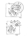
- the transport device 10 (see Figure 2) comprises a d.c. transport motor 16 having a rotor with a shaft 17 on which a pinion 18 is fixed; the pinion 18 can mesh with the teeth of a gear 19 of a transmission unit 21.
- the motor 16 comprises a stator provided with a coupling portion 22 by means of which it is engaged and guided in a seat 23 of a support 24 and is fixed to the support 24 by means of three screws 26 (see Figure 4) received in respective slots 27.
- the slots 27 in the support 24 permit centering and adjustment of the angular position of the stator of the motor 16 with respect to the support 24, in the assembly phase.
- the transmission unit 21 (see Figure 2) comprises the gear 19 and a toothed pulley 28 which is coaxial with the gear 19 and which is continuously engaged with a toothed belt 29 which in turn is connected to the print unit 13 (see Figure 1) for displacement thereof in both directions.
- the gear 19 (see Figure 2) and the toothed pulley 28 are rigidly connected by a hollow sleeve 31.
- the transmission unit 21 is rotatable by means of two roller bearing assemblies 32 on a shaft 33. One end 34 of the shaft 33 is fixed to a fixed support 36 and another end 37 passes through an opening 38 in the support 24 and is fixed by means of a screw 39 (see Figure 4) to an arm 41 of a lever 42 which in turn is pivoted on a pin 43 on the support 24.
- a spring 44 rotates the lever 42 in the clockwise direction and urges the shaft 33 and thus the transmission unit 21 (see Figure 3) towards the shaft 17 of the motor 16, holding the gear 19 engaged with the pinion 18.
- the lever 53 comprises two projections 54 which are guided and housed in corresponding openings 56 in a support 57.
- An adjusting screw 58 with a lock nut 59 positions the lever 53 away from or close to the fixed support 57 so as to produce a predetermined tension, for example about 900 grams, in the toothed belt 29.
- the tension in the toothed belt 29 around the pulley 28 contributes to positioning the transmission unit 21 (see Figure 2) with respect to the motor 16.
- the tension in the toothed belt 29, which is reduced in accordance with the short lever arm acting thereon, and the force of the spring 44, corresponding to about 200 grams, generate a force such as to hold the transmission unit 22 constantly urged towards the motor 16 so that the gear 19 is always engaged, without play, with the pinion 18. That provides a self-regulating device which permits the radial clearances between the pinion 18 and the gear 19 to be automatically taken up.
- That structure makes it possible to achieve positioning with a high degree of accuracy and in a repetitive manner of the print unit 13 in front of the point of printing on the platen roller 11, even at high speed and after a long period of use.
- the transmission ratio between the pinion 18 and the gear 19 is 18/96 and that makes it possible to use a d.c. motor 16 of reduced power, with the movement being transmitted silently, even at high speed.
- a tooth of a height H comprises an addendum, that is to say the part which is between the pitch circle which is shown by the dash-dotted line in Figure 6, and the tip of the tooth, which is equal to m, and a dedendum, that is to say the part between the base of the tooth and the pitch circle, which is equal to 7/6 m .
- the addendum according to the invention is in this case a fraction of the modulus and is always less by about 1/10 than the value of the modulus, while the dedendum retains its value which is equal to seven sixths of the modulus. Therefore the value of H is reduced by at least 1/10 with respect to the standardised value.
- the tip of a tooth as indicated at 71 and the base between two opposite teeth 72 and 73 there is always a gap which is greater than that prescribed in meshing between standardised teeth.
- transport device 10 for the print unit 13 may be the subject of modifications, and improvements within the scope of the claims.
- the position of the gear 19 is fixed.
- the motor 16 is mounted, e.g. on trunnions, so that it can tilt and a spring urges the motor to tilt in the sense forcing the pinion 18 into mesh with the gear 19.
Landscapes
- Handling Of Sheets (AREA)
- Character Spaces And Line Spaces In Printers (AREA)
- Delivering By Means Of Belts And Rollers (AREA)
Applications Claiming Priority (2)
| Application Number | Priority Date | Filing Date | Title |
|---|---|---|---|
| IT6749085 | 1985-05-29 | ||
| IT67490/85A IT1183859B (it) | 1985-05-29 | 1985-05-29 | Dispositivo di trasporto per unita di stampa di macchine scriventi |
Publications (3)
| Publication Number | Publication Date |
|---|---|
| EP0203731A2 true EP0203731A2 (de) | 1986-12-03 |
| EP0203731A3 EP0203731A3 (en) | 1988-05-11 |
| EP0203731B1 EP0203731B1 (de) | 1991-07-24 |
Family
ID=11302857
Family Applications (1)
| Application Number | Title | Priority Date | Filing Date |
|---|---|---|---|
| EP86303254A Expired EP0203731B1 (de) | 1985-05-29 | 1986-04-29 | Transportvorrichtung für die Druckeinheit in einer Druckmaschine |
Country Status (5)
| Country | Link |
|---|---|
| US (1) | US4718786A (de) |
| EP (1) | EP0203731B1 (de) |
| JP (1) | JPS61293878A (de) |
| DE (1) | DE3680385D1 (de) |
| IT (1) | IT1183859B (de) |
Families Citing this family (1)
| Publication number | Priority date | Publication date | Assignee | Title |
|---|---|---|---|---|
| CN112682419B (zh) * | 2021-03-16 | 2021-05-18 | 长岛高能聚氨酯有限公司 | 一种铝质关节球销总成及其生产工艺 |
Family Cites Families (7)
| Publication number | Priority date | Publication date | Assignee | Title |
|---|---|---|---|---|
| DE2926962A1 (de) * | 1979-07-04 | 1981-01-22 | Olympia Werke Ag | Antriebsvorrichtung fuer einen druckwerkswagen in schreib- o.ae. bueromaschinen |
| CH636050A5 (fr) * | 1980-05-20 | 1983-05-13 | Hermes Precisa International | Machine a ecrire. |
| US4318625A (en) * | 1980-09-29 | 1982-03-09 | International Business Machines Corporation | Stepper motor load tuning |
| JPS5829690A (ja) * | 1981-08-17 | 1983-02-21 | Ricoh Co Ltd | プリンタのモ−タ取付構造 |
| US4395151A (en) * | 1981-11-02 | 1983-07-26 | Zenith Radio Corporation | Print head drive belt tensioning means and method for line printer |
| DE3210758C1 (de) * | 1982-03-24 | 1983-07-28 | Triumph-Adler Aktiengesellschaft für Büro- und Informationstechnik, 8500 Nürnberg | Vorrichtung zum Lagern der Umlenkrollen und zum Spannen eines Zugmitteltriebes |
| IT1158811B (it) * | 1983-02-28 | 1987-02-25 | Olivetti & Co Spa | Dispositivo per accoppiare un disco portacaratteri ad un motore di selezione |
-
1985
- 1985-05-29 IT IT67490/85A patent/IT1183859B/it active
-
1986
- 1986-04-29 DE DE8686303254T patent/DE3680385D1/de not_active Expired - Lifetime
- 1986-04-29 EP EP86303254A patent/EP0203731B1/de not_active Expired
- 1986-05-23 US US06/866,255 patent/US4718786A/en not_active Expired - Fee Related
- 1986-05-27 JP JP61122057A patent/JPS61293878A/ja active Pending
Also Published As
| Publication number | Publication date |
|---|---|
| DE3680385D1 (de) | 1991-08-29 |
| EP0203731B1 (de) | 1991-07-24 |
| JPS61293878A (ja) | 1986-12-24 |
| US4718786A (en) | 1988-01-12 |
| IT1183859B (it) | 1987-10-22 |
| EP0203731A3 (en) | 1988-05-11 |
| IT8567490A0 (it) | 1985-05-29 |
| IT8567490A1 (it) | 1986-11-29 |
Similar Documents
| Publication | Publication Date | Title |
|---|---|---|
| EP0364262B1 (de) | Drucker mit Vorrichtung zum Einstellen der Schlagweite des Kopfes | |
| KR100303961B1 (ko) | 구동장치 | |
| GB1581143A (en) | Paper feed mechanism | |
| EP0143522B1 (de) | Zeilenschaltmechanismus für Druckmaschine | |
| EP0203731A2 (de) | Transportvorrichtung für die Druckeinheit in einer Druckmaschine | |
| WO1998000655A1 (en) | Anti-backlash mechanism for a rotary stage | |
| US5966987A (en) | Controlling device of tunable filter | |
| EP0139411B1 (de) | Vorrichtung zur Kontrolle der Drehbewegung einer Schreibwalze | |
| JPS6022637B2 (ja) | 自動消印機における価格印字用の数字輪と計数器用の送りドラム機構とをロツクして整列させる装置 | |
| EP0079184A1 (de) | Geteiltes spielfreies Zahnrad aus gegeneinander federnd vorgespannten Teilen | |
| EP1780029A1 (de) | Drucker mit Vorschubeinrichtung für einen Druckträger | |
| US4493571A (en) | Print guide mechanism | |
| KR960016554B1 (ko) | 다색 리본 카세트의 위치조정장치 | |
| US4349284A (en) | Assembly for moving printing means of a printing machine | |
| EP0206477B1 (de) | Auswahlvorrichtung für ein Typenträgerelement an Druckmaschinen | |
| US4697943A (en) | Electric platen driving device with manual override | |
| US5039240A (en) | Printing device with ribbon cassette shifting mechanism | |
| JPS61112860A (ja) | 歯車 | |
| US5402717A (en) | Device for setting printwheels in a postage meter | |
| US4582440A (en) | Line spacing device for an office machine | |
| EP0381100B1 (de) | Antriebsanordnung für ein Geräteunterteil | |
| US5719381A (en) | Postage meter with hollow rotor axle | |
| US4383776A (en) | Typewriter with carriage escape bar adjustment | |
| KR900001925Y1 (ko) | 휠 기어(wheel gear)의 백래시 보상장치(back-lash compensator) | |
| JPH02292549A (ja) | 歯車伝達機構及び歯車伝達機構を用いた紙送り装置 |
Legal Events
| Date | Code | Title | Description |
|---|---|---|---|
| PUAI | Public reference made under article 153(3) epc to a published international application that has entered the european phase |
Free format text: ORIGINAL CODE: 0009012 |
|
| AK | Designated contracting states |
Kind code of ref document: A2 Designated state(s): DE FR GB |
|
| PUAL | Search report despatched |
Free format text: ORIGINAL CODE: 0009013 |
|
| RHK1 | Main classification (correction) |
Ipc: B41J 19/20 |
|
| AK | Designated contracting states |
Kind code of ref document: A3 Designated state(s): DE FR GB |
|
| 17P | Request for examination filed |
Effective date: 19881101 |
|
| 17Q | First examination report despatched |
Effective date: 19900406 |
|
| GRAA | (expected) grant |
Free format text: ORIGINAL CODE: 0009210 |
|
| AK | Designated contracting states |
Kind code of ref document: B1 Designated state(s): DE FR GB |
|
| REF | Corresponds to: |
Ref document number: 3680385 Country of ref document: DE Date of ref document: 19910829 |
|
| ET | Fr: translation filed | ||
| PLBE | No opposition filed within time limit |
Free format text: ORIGINAL CODE: 0009261 |
|
| STAA | Information on the status of an ep patent application or granted ep patent |
Free format text: STATUS: NO OPPOSITION FILED WITHIN TIME LIMIT |
|
| 26N | No opposition filed | ||
| PGFP | Annual fee paid to national office [announced via postgrant information from national office to epo] |
Ref country code: FR Payment date: 19930408 Year of fee payment: 8 |
|
| PGFP | Annual fee paid to national office [announced via postgrant information from national office to epo] |
Ref country code: GB Payment date: 19930419 Year of fee payment: 8 |
|
| PGFP | Annual fee paid to national office [announced via postgrant information from national office to epo] |
Ref country code: DE Payment date: 19930506 Year of fee payment: 8 |
|
| PG25 | Lapsed in a contracting state [announced via postgrant information from national office to epo] |
Ref country code: GB Effective date: 19940429 |
|
| PG25 | Lapsed in a contracting state [announced via postgrant information from national office to epo] |
Ref country code: FR Effective date: 19941229 |
|
| PG25 | Lapsed in a contracting state [announced via postgrant information from national office to epo] |
Ref country code: DE Effective date: 19950103 |
|
| GBPC | Gb: european patent ceased through non-payment of renewal fee |
Effective date: 19940429 |
|
| REG | Reference to a national code |
Ref country code: FR Ref legal event code: ST |