EP0203797A2 - Appareil pour enregistrer et/ou reproduire un signal numérique - Google Patents
Appareil pour enregistrer et/ou reproduire un signal numérique Download PDFInfo
- Publication number
- EP0203797A2 EP0203797A2 EP86303960A EP86303960A EP0203797A2 EP 0203797 A2 EP0203797 A2 EP 0203797A2 EP 86303960 A EP86303960 A EP 86303960A EP 86303960 A EP86303960 A EP 86303960A EP 0203797 A2 EP0203797 A2 EP 0203797A2
- Authority
- EP
- European Patent Office
- Prior art keywords
- signal
- recording
- skip
- programme
- code
- Prior art date
- Legal status (The legal status is an assumption and is not a legal conclusion. Google has not performed a legal analysis and makes no representation as to the accuracy of the status listed.)
- Granted
Links
Images

Classifications
-
- G—PHYSICS
- G11—INFORMATION STORAGE
- G11B—INFORMATION STORAGE BASED ON RELATIVE MOVEMENT BETWEEN RECORD CARRIER AND TRANSDUCER
- G11B15/00—Driving, starting or stopping record carriers of filamentary or web form; Driving both such record carriers and heads; Guiding such record carriers or containers therefor; Control thereof; Control of operating function
- G11B15/02—Control of operating function, e.g. switching from recording to reproducing
- G11B15/05—Control of operating function, e.g. switching from recording to reproducing by sensing features present on or derived from record carrier or container
- G11B15/087—Control of operating function, e.g. switching from recording to reproducing by sensing features present on or derived from record carrier or container by sensing recorded signals
-
- G—PHYSICS
- G11—INFORMATION STORAGE
- G11B—INFORMATION STORAGE BASED ON RELATIVE MOVEMENT BETWEEN RECORD CARRIER AND TRANSDUCER
- G11B15/00—Driving, starting or stopping record carriers of filamentary or web form; Driving both such record carriers and heads; Guiding such record carriers or containers therefor; Control thereof; Control of operating function
- G11B15/18—Driving; Starting; Stopping; Arrangements for control or regulation thereof
- G11B15/1808—Driving of both record carrier and head
- G11B15/1875—Driving of both record carrier and head adaptations for special effects or editing
-
- G—PHYSICS
- G11—INFORMATION STORAGE
- G11B—INFORMATION STORAGE BASED ON RELATIVE MOVEMENT BETWEEN RECORD CARRIER AND TRANSDUCER
- G11B20/00—Signal processing not specific to the method of recording or reproducing; Circuits therefor
- G11B20/10—Digital recording or reproducing
- G11B20/10527—Audio or video recording; Data buffering arrangements
-
- G—PHYSICS
- G11—INFORMATION STORAGE
- G11B—INFORMATION STORAGE BASED ON RELATIVE MOVEMENT BETWEEN RECORD CARRIER AND TRANSDUCER
- G11B20/00—Signal processing not specific to the method of recording or reproducing; Circuits therefor
- G11B20/10—Digital recording or reproducing
- G11B20/12—Formatting, e.g. arrangement of data block or words on the record carriers
- G11B20/1201—Formatting, e.g. arrangement of data block or words on the record carriers on tapes
- G11B20/1207—Formatting, e.g. arrangement of data block or words on the record carriers on tapes with transverse tracks only
- G11B20/1208—Formatting, e.g. arrangement of data block or words on the record carriers on tapes with transverse tracks only for continuous data, e.g. digitised analog information signals, pulse code modulated [PCM] data
-
- G—PHYSICS
- G11—INFORMATION STORAGE
- G11B—INFORMATION STORAGE BASED ON RELATIVE MOVEMENT BETWEEN RECORD CARRIER AND TRANSDUCER
- G11B27/00—Editing; Indexing; Addressing; Timing or synchronising; Monitoring; Measuring tape travel
- G11B27/02—Editing, e.g. varying the order of information signals recorded on, or reproduced from, record carriers
- G11B27/031—Electronic editing of digitised analogue information signals, e.g. audio or video signals
- G11B27/036—Insert-editing
-
- G—PHYSICS
- G11—INFORMATION STORAGE
- G11B—INFORMATION STORAGE BASED ON RELATIVE MOVEMENT BETWEEN RECORD CARRIER AND TRANSDUCER
- G11B27/00—Editing; Indexing; Addressing; Timing or synchronising; Monitoring; Measuring tape travel
- G11B27/10—Indexing; Addressing; Timing or synchronising; Measuring tape travel
- G11B27/19—Indexing; Addressing; Timing or synchronising; Measuring tape travel by using information detectable on the record carrier
- G11B27/28—Indexing; Addressing; Timing or synchronising; Measuring tape travel by using information detectable on the record carrier by using information signals recorded by the same method as the main recording
- G11B27/30—Indexing; Addressing; Timing or synchronising; Measuring tape travel by using information detectable on the record carrier by using information signals recorded by the same method as the main recording on the same track as the main recording
- G11B27/3027—Indexing; Addressing; Timing or synchronising; Measuring tape travel by using information detectable on the record carrier by using information signals recorded by the same method as the main recording on the same track as the main recording used signal is digitally coded
-
- G—PHYSICS
- G11—INFORMATION STORAGE
- G11B—INFORMATION STORAGE BASED ON RELATIVE MOVEMENT BETWEEN RECORD CARRIER AND TRANSDUCER
- G11B27/00—Editing; Indexing; Addressing; Timing or synchronising; Monitoring; Measuring tape travel
- G11B27/10—Indexing; Addressing; Timing or synchronising; Measuring tape travel
- G11B27/19—Indexing; Addressing; Timing or synchronising; Measuring tape travel by using information detectable on the record carrier
- G11B27/28—Indexing; Addressing; Timing or synchronising; Measuring tape travel by using information detectable on the record carrier by using information signals recorded by the same method as the main recording
- G11B27/30—Indexing; Addressing; Timing or synchronising; Measuring tape travel by using information detectable on the record carrier by using information signals recorded by the same method as the main recording on the same track as the main recording
- G11B27/3027—Indexing; Addressing; Timing or synchronising; Measuring tape travel by using information detectable on the record carrier by using information signals recorded by the same method as the main recording on the same track as the main recording used signal is digitally coded
- G11B27/3063—Subcodes
-
- G—PHYSICS
- G11—INFORMATION STORAGE
- G11B—INFORMATION STORAGE BASED ON RELATIVE MOVEMENT BETWEEN RECORD CARRIER AND TRANSDUCER
- G11B20/00—Signal processing not specific to the method of recording or reproducing; Circuits therefor
- G11B20/10—Digital recording or reproducing
- G11B20/12—Formatting, e.g. arrangement of data block or words on the record carriers
- G11B20/1201—Formatting, e.g. arrangement of data block or words on the record carriers on tapes
- G11B20/1211—Formatting, e.g. arrangement of data block or words on the record carriers on tapes with different data track configurations
-
- G—PHYSICS
- G11—INFORMATION STORAGE
- G11B—INFORMATION STORAGE BASED ON RELATIVE MOVEMENT BETWEEN RECORD CARRIER AND TRANSDUCER
- G11B2220/00—Record carriers by type
- G11B2220/90—Tape-like record carriers
-
- G—PHYSICS
- G11—INFORMATION STORAGE
- G11B—INFORMATION STORAGE BASED ON RELATIVE MOVEMENT BETWEEN RECORD CARRIER AND TRANSDUCER
- G11B2220/00—Record carriers by type
- G11B2220/90—Tape-like record carriers
- G11B2220/91—Helical scan format, wherein tracks are slightly tilted with respect to tape direction, e.g. VHS, DAT, DVC, AIT or exabyte
- G11B2220/913—Digital audio tape [DAT] format
-
- G—PHYSICS
- G11—INFORMATION STORAGE
- G11B—INFORMATION STORAGE BASED ON RELATIVE MOVEMENT BETWEEN RECORD CARRIER AND TRANSDUCER
- G11B27/00—Editing; Indexing; Addressing; Timing or synchronising; Monitoring; Measuring tape travel
- G11B27/02—Editing, e.g. varying the order of information signals recorded on, or reproduced from, record carriers
- G11B27/031—Electronic editing of digitised analogue information signals, e.g. audio or video signals
- G11B27/032—Electronic editing of digitised analogue information signals, e.g. audio or video signals on tapes
Definitions
- This invention relates to apparatus for recording and/or reproducing a digital signal, and more particularly, but not exclusively, to apparatus for recording and/or reproducing a digital programme information signal in a so-called digital audio tape recorder (DAT).
- DAT digital audio tape recorder
- So-called DATs that are now under development are of the fixed or stationary head type (S-DAT) or of the rotary head type (R-DAT).
- S-DATs a digital audio signal is recorded in many tracks parallel to the longitudinal direction of a tape by using a multi-track stationary head.
- R-DATs a digital audio signal is recorded in tracks oblique to the longitudinal direction of the tape by rotary heads of a helical scanning system.
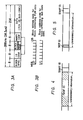
- Figure 1 of the accompanying drawings shows a tape format used in a previously proposed R-DAT. Examples of various dimensions in Figure 1 are:
- a rotary head drum about which the tape is wrapped has a diameter of 30 mm and is rotated at a speed of 2000 rpm, by way of example.
- the recording speed (Vh in Figure 1) is selected to be 3.13 mm/s, and the tape wrapping angle is selected to be 90°.
- the recording is carried out with a track format and a block format as shown in Figure 2 and Figures 3A and 3B of the accompanying drawings, respectively.
- positional information such as, a programme number, a track number, a time code (code indicating the time, in minutes and seconds, from the starting point of the programme) and the like, and sub-codes containing other necessary auxiliary data are also recorded.
- one track which is recorded by one rotary head, is formed of 196 blocks, in which a pulse code modulated (PCM) audio data recording area comprising 128 blocks is substantially centred with respect to the length of the track.
- An automatic track following (ATF) area comprising five blocks, and in which a pilot signal for the tracking operation is recorded, is provided at opposite sides of the PCM audio data recording area, and sub-code areas 1 and 2 each comprising eight blocks for recording sub-code data are provided outside the ATF areas.
- PCM pulse code modulated
- ATF automatic track following
- the PCM area and the sub-code areas 1 and 2 are provided with respective phase locked loop (PLL) areas of two blocks each for synchronization.
- GAP areas of three blocks each are provided between the PCM area and the ATF areas, and between the latter and the sub-code areas 1 and 2. If the timing for switching the recording mode and the playback mode is matched with the gap areas between the PCM area and the sub-code areas 1 and 2, it becomes possible independently to record the PCM audio signal or the sub-code signal.
- the track format of Figure 2 is completed by margin areas of eleven blocks at the opposite ends of the track, and by postamble areas of one block situated between the sub-code area 1 and the adjacent GAP, and between the sub-code area 2 and the adjacent margin area.
- the numerals in Figure 2 will be seen to indicate the numbers of blocks that constitute the respective areas.
- each block is formed of 288 bits and includes an 8-bit block synchronizing signal, an 8-bit identifying code (ID code), an 8-bit block address code, an 8-bit parity code and 256-bit data (PCM data or sub-code data) which are sequentially located in the order given.
- ID code 8-bit identifying code
- 8-bit block address code 8-bit block address code
- 8-bit parity code 256-bit data
- PCM data or sub-code data 256-bit data
- the ID code in each block containing PCM data is used to indicate the use of audio data, emphasis characteristic, quantization characteristic, sampling frequency, the number of channels, the presence or absence of editing of the PCM audio signal and the like.
- a recording start point (head) of the recorded programme interval to be skipped in the playback mode and so on are assigned to the MSB, second most significant bit (2SB), third most significant bit (3SB), ... , of the 8-bit ID code, respectively.
- the 2SB of the ID code in a block containing sub-code data becomes "1" for ten seconds and is used as a programme start signal.
- the 2SB of the ID code in a block containing sub-code data is recorded as "0" in portions other than the start portion of each programme.
- the interval on the tape in which the 3SB of the ID code in a block containing sub-code data becomes "0" is normally reproduced in the playback mode, whereas, in the interval in which the 3SB of the ID code of each such block becomes "1", the programme recorded in that interval is considered to be unnecessary and is skipped in the playback mode.
- Such 3SB of the ID code is referred to as a "skip bit" hereinafter.
- the blank state or interval be detected by sensing the level of the reproduced audio signal, and when this blank state or interval lasts, for example, more than ten seconds, the magnetic tape is transported at a high speed, for example, sixteen times the normal tape speed.
- an apparatus for recording and/or reproducing a programme information signal comprising:
- an embodiment of the present invention provides an apparatus for recording and/or reproducing a digital signal comprising a recording medium on which at least a programme information signal and a programme start signal indicating the start of the programme information signal are recorded, and means for recording a skip identifying code signal, that is, a skip bit, only at a start portion of unnecessary programme information on the recording medium.
- a skip identifying code signal that is, a skip bit
- a skip identifying code signal (SKIP ID) relating to unnecessary information is recorded only at the start end portion of the unnecessary information and for a short time period, for example, corresponding to at least two tracks.
- the end or terminal portion of the unnecessary information is indicated by the start end portion of the succeeding programme start signal (START ID) that was previously recorded on the recording medium.
- the skip identifying code signal (SKIP ID) is recorded in the after-recording mode and, for the duration of the unnecessary information portion, the recording medium is transported at an arbitrary high speed at which the succeeding START ID can still be detected.
- the apparatus is returned to the playback mode.
- the apparatus In the playback mode, when the SKIP ID is detected, the apparatus is changed-over to the high speed (fast-forward) search mode and the unnecessary information is skipped until the next START ID is detected, and then the apparatus is returned to the playback mode.
- the SKIP ID is recorded only at the start end portion of the unnecessary information for a short time period and the recording medium is then transported at the arbitrary high speed until the succeeding START ID is detected, it is not necessary to record the SKIP ID over the whole interval of the unnecessary information. Therefore, unlike the prior proposals mentioned above, the time necessary for recording the SKIP ID can be reduced considerably. Further, when the recorded SKIP ID is to be erased, such code can be erased in a quite short time period.
- an analog signal for example, an audio signal
- LPF low-pass filter
- A/D analog-to-digital converter 3 in which the analog signal is converted to a digital signal.
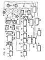
- the digital signal from A/D converter 3 is supplied through a fixed contact a of a switching circuit 4 to a recording signal generating circuit 5. If the switching circuit 4 is changed-over to its other fixed contact b, a digital signal supplied to a terminal 6 may be directly supplied to the recording signal generating circuit 5.
- the recording signal generating circuit 5 carries out, on the basis of a timing signal TM from a timing signal generating circuit 7, suitable signal processing, such as, the addition of an error correction code for the data, the interleaving of the data, the modulation of the data and so on.
- the resulting processed digital signal is supplied from the recording signal generating circuit 5 to a switching circuit 8.
- the switching circuit 8 is used to switch from one to the other of two rotary magnetic heads 11A and 11B in accordance with a switching signal SW1 from the timing signal generating circuit 7.
- the switching circuit 8 is alternately switched by the signal SW1 between a half-revolution period including a tape contact period of the rotary head 11A and a half-revolution period including a tape contact period of the rotary head 11B.
- the timing signal generating circuit 7 is supplied with a pulse having a frequency 33.3 Hz indicative of the rotary phases of the rotary heads 11A and 11B and which is generated from a pulse generator (not shown) in synchronism with the rotation of a motor which rotates the rotary heads 11A and 11B.
- the signal from the switching circuit 8 which is changed-over by the switching signal SW1 from the timing signal generating circuit 7 is amplified by one or the other of amplifiers 9A and 9B and then supplied through a contact R of a switching circuit 10A or 10B to the rotary magnetic head 11A or 11B and thereby recorded on a magnetic tape 14 running between reels 12 and 13.
- the switching circuits 10A and 10B engage their contacts R in the recording mode, and engage their contacts P in the reproducing or playback mode.
- Amplifiers 15A and 15B are connected to receive and amplify reproduced outputs alternately provided by the corresponding rotary heads 11A and 11B when the switching circuits 10A and 10B engage their respective contacts P.
- the outputs from amplifiers 15A and 15B are supplied to respective fixed contacts of a switching circuit 16.
- the switching circuit 16 In response to a switching signal SW2 having a frequency of 33.3 Hz and being supplied from the timing signal generating circuit 7, the switching circuit 16 is alternately changed-over, similarly to the action of the switching circuit 8 in the recording mode, between the half-revolution period including the tape contact period of the rotary head 11A and the half-revolution period including the tape contact period of the rotary head 11B.
- the output signal SOUT from the switching circuit 16 is supplied through an electromagnetic transducer system formed of an equalizer 17, a comparator 18 and a PLL circuit 19 to an error correction circuit 20 in which error correction is carried out, if necessary.
- the resulting signal from the error correction circuit 20 is supplied to a digital-to-analog (D/A) converter 21 in which the reproduced digital signal is converted to an analog signal.
- the resulting analog signal from the D/A converter 21 is supplied through an LPF 22 to an output terminal 23 at which the reproduced analog signal is derived.
- the digital data When it is desired that the digital data be directly obtained, it can be derived from a terminal 24 connected to the output of the error correction circuit 20.
- a sub-code microcomputer 25 serving as an interface is connected with an output of the error correction circuit 20.
- the sub-code microcomputer 25 is used to extract the sub-code containing the programme number, the time code and so on, and in which the respective data are identified.
- a control signal Cl based on the identified data is supplied from the sub-code microcomputer 25 to a system controller 26 that employs a microcomputer and is arranged to control the whole system.
- the system controller 26 is provided with a plurality of switches or push buttons necessary for selecting the desired mode of operation.
- a skip identifying code recording (SKIP ID REC) push button 27 and a skip on and off (SKIP ID ON/OFF) push button 28 are illustrated as being typical of such push buttons.
- the SKIP ID REC push button 27 is actuable to cause recording of the SKIP ID in the after-recording mode.
- the SKIP ID ON/OFF push button 28 is displaced to its ON position when it is desired to skip the unnecessary information in the playback mode, while it is turned off when skipping of the unnecessary information is not desired even although the SKIP ID exists on the tape.
- a drum servo circuit 30 is provided which is controlled by the system controller 26. This drum servo circuit 30 is used to control a drum motor 31 for rotating a tape guide drum (not shown) on which the rotary heads 11A and 11B are mounted.
- a reel driving circuit 32 provides reel drive signals RD to reel motors 33 and 34 for rotating the reels 12 and 13, respectively. In response to a suitable mode switching signal MS from the system controller 26, the reel driving circuit 32 changes the level of drive currents that are supplied therefrom to the reel motors 33 and 34 for controlling their operations.
- a capstan servo circuit 35 is provided which is also controlled by the system controller 26 and the capstan servo circuit 35 is used to control a capstan motor 37 which drives a capstan 36.
- a capstan motor 37 which drives a capstan 36.
- a pinch roller and a conventional plunger circuit (not shown) by which movements of the pinch roller against and away from capstan 36, with the tape 14 therebetween, are suitably controlled.
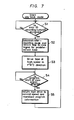
- the system controller 26 is operated to place the recording and/or reproducing apparatus in the playback mode for reproducing the recorded information or audio signal. Thereafter, while monitoring the audio signal developed at the output terminal 23, when a portion of the audio signal that the user does not want to listen to again, that is, unnecessary programme information, is heard, the SKIP ID REC push button 27 is depressed or actuated. When actuation of the SKIP ID REC pushbutton 27 is detected in step 51, the recording and reproducing apparatus is controlled by the system controller 26 so as to be placed in the after-recording mode.
- the SKIP ID derived from the recording signal generating circuit 5 is recorded by the rotary heads 11A and 11B at the 3SB in the ID code of blocks in the sub-code area of tracks on the tape 14 containing the start end portion of the unnecessary information. More particularly, in step S2, "1" is recorded for a predetermined time period, for example, at least, the time corresponding to the scanning of two tracks, at the 3SB of the ID code in blocks containing sub-code data.
- the reel drive circuit 32 is controlled by the system controller 26 so that the tape 14 can be moved at an arbitrary high tape speed at which at least the START ID recorded on the tape 14 can be detected (at step S3).
- the system controller 26 controls the apparatus to return to the playback mode with the tape 14 being driven at its normal speed so as to reproduce programme information subsequent to the START ID, as in step S5.
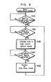
- the apparatus When a play button (not shown) is depressed, the apparatus is controlled by the system controller 26 so as to be placed in the playback mode. Thereafter, if the SKIP ID ON/OFF push button 28 is detected in step S10 to be in its ON position and, in step S20, the SKIP ID is detected in the sub-code area, that is, the 3SB of the ID code signal recorded on the sub-code area is detected to be "1", the apparatus is changed-over in step S30 from the playback mode to the high speed search mode in which the tape 14 is transported at high tape speed.
- the ID code signal in the sub-code area is reproduced and, when the next START ID is detected in step S40, that is, the 2SB of the ID code signal recorded in the sub-code area is detected to be "1", the apparatus is returned, in step S50, from the high speed search mode to the playback mode. In other words, the unnecessary information portion is skipped.
- step S10 if the SKIP ID ON/OFF push button 28 is detected to be in its OFF position in step S10, even if the SKIP ID is detected in the playback mode, skipping of the respective information is not carried out, and the programme information is reproduced as it is, that is, without omission or skipping.
- the tape 14 is transported at an arbitrary high speed until the next START ID is detected, that is, until the end portion of the unnecessary information.
Landscapes
- Engineering & Computer Science (AREA)
- Signal Processing (AREA)
- Multimedia (AREA)
- Signal Processing For Digital Recording And Reproducing (AREA)
- Indexing, Searching, Synchronizing, And The Amount Of Synchronization Travel Of Record Carriers (AREA)
- Digital Magnetic Recording (AREA)
Applications Claiming Priority (2)
| Application Number | Priority Date | Filing Date | Title |
|---|---|---|---|
| JP60116213A JP2544333B2 (ja) | 1985-05-29 | 1985-05-29 | 信号再生装置 |
| JP116213/85 | 1985-05-29 |
Publications (3)
| Publication Number | Publication Date |
|---|---|
| EP0203797A2 true EP0203797A2 (fr) | 1986-12-03 |
| EP0203797A3 EP0203797A3 (en) | 1988-04-06 |
| EP0203797B1 EP0203797B1 (fr) | 1990-09-26 |
Family
ID=14681634
Family Applications (1)
| Application Number | Title | Priority Date | Filing Date |
|---|---|---|---|
| EP86303960A Expired EP0203797B1 (fr) | 1985-05-29 | 1986-05-23 | Appareil pour enregistrer et/ou reproduire un signal numérique |
Country Status (5)
| Country | Link |
|---|---|
| US (2) | US4688116A (fr) |
| EP (1) | EP0203797B1 (fr) |
| JP (1) | JP2544333B2 (fr) |
| CA (1) | CA1263746A (fr) |
| DE (1) | DE3674466D1 (fr) |
Cited By (11)
| Publication number | Priority date | Publication date | Assignee | Title |
|---|---|---|---|---|
| FR2600196A1 (fr) * | 1986-06-17 | 1987-12-18 | Sony Corp | Appareil d'enregistrement et de reproduction d'un signal de commande |
| EP0276837A1 (fr) * | 1987-01-28 | 1988-08-03 | Sony Corporation | Appareil d'enregistrement et de reproduction d'un signal |
| US4873589A (en) * | 1986-12-19 | 1989-10-10 | Sony Corporation | Data recorder and method |
| DE3917009A1 (de) * | 1988-07-21 | 1990-01-25 | Pioneer Electronic Corp | Digitales tonbandgeraet und programmsprungwahlverfahren hierfuer |
| EP0278702A3 (en) * | 1987-02-06 | 1990-04-04 | Sony Corporation | Apparatus for reproducing a digital signal |
| EP0365544A4 (en) * | 1987-05-11 | 1991-06-05 | Exabyte Corporation | Forming digital data for magnetic tape |
| EP0432759A1 (fr) * | 1989-12-12 | 1991-06-19 | Matsushita Electric Industrial Co., Ltd. | Procédé d'enregistrement de données, méhode de recherche de fin d'un enregistrement et procédé d'assemblage de données |
| US5134529A (en) * | 1987-12-14 | 1992-07-28 | Sony Corporation | Apparatus and method for recording a digital signal |
| EP0526739A1 (fr) * | 1991-07-10 | 1993-02-10 | Hitachi, Ltd. | Appareil d'enregistrement et de reproduction à bande magnétique |
| EP0540352A3 (en) * | 1991-10-31 | 1993-06-02 | Sony Corporation | Data recording/reproducing device |
| EP0644662A3 (fr) * | 1993-09-20 | 1996-07-31 | Hudson Soft Co Ltd | Récepteur radio avec une fonction d'enregistrement et reproduction. |
Families Citing this family (15)
| Publication number | Priority date | Publication date | Assignee | Title |
|---|---|---|---|---|
| JP2659533B2 (ja) * | 1986-04-18 | 1997-09-30 | 三菱電機株式会社 | テープレコーダ装置 |
| JPH07118185B2 (ja) * | 1986-07-22 | 1995-12-18 | ソニー株式会社 | デジタル信号記録再生装置 |
| JPH0636256B2 (ja) * | 1987-02-04 | 1994-05-11 | ヤマハ株式会社 | 回転ヘッド形磁気記録媒体再生装置の倍速再生装置 |
| JPS63161431U (fr) * | 1987-04-10 | 1988-10-21 | ||
| US4982305A (en) * | 1988-02-25 | 1991-01-01 | Sony Corporation | Tape recorder with automatic pause mode setting |
| KR920008937B1 (ko) * | 1989-09-08 | 1992-10-12 | 삼성전자 주식회사 | 기록 매체 구동장치의 무녹화 지대 재생 방법 |
| DE4110153C3 (de) * | 1990-03-27 | 1999-07-15 | Sharp Kk | Aufzeichnungs- und Wiedergabegerät |
| JPH0490181A (ja) * | 1990-07-31 | 1992-03-24 | Sony Corp | 記録再生装置 |
| JPH04259965A (ja) * | 1991-02-15 | 1992-09-16 | Sony Corp | 情報信号記録/再生装置 |
| JPH05266636A (ja) * | 1992-03-23 | 1993-10-15 | Sony Corp | ディスク記録再生装置 |
| JPH06150633A (ja) * | 1992-10-30 | 1994-05-31 | Sony Corp | 磁気記録装置及び再生装置 |
| JP3295473B2 (ja) * | 1993-02-01 | 2002-06-24 | パイオニア株式会社 | リアルタイム編集機能を有するビデオディスクレコーダ |
| US5991111A (en) | 1997-07-31 | 1999-11-23 | Howard; James R. | Edge recorded magnetic tape and read head |
| US6781638B1 (en) | 2001-08-10 | 2004-08-24 | Universal Electronics Inc. | Universal remote control capable of simulating a skip search |
| US7457516B2 (en) * | 2004-05-07 | 2008-11-25 | Intervideo Inc. | Video editing system and method of computer system |
Family Cites Families (5)
| Publication number | Priority date | Publication date | Assignee | Title |
|---|---|---|---|---|
| US3166328A (en) * | 1962-07-25 | 1965-01-19 | Roberts Irving | Magnetic tape recording and playback systems |
| JPS6043572B2 (ja) * | 1979-07-16 | 1985-09-28 | 日本ビクター株式会社 | 自動スキツプ機能を有するテ−プレコ−ダ |
| JPS5776660A (en) * | 1980-10-31 | 1982-05-13 | Toshiba Corp | Recording system for variable-length picture information |
| JPS57208681A (en) * | 1981-06-17 | 1982-12-21 | Fuji Photo Film Co Ltd | Cassette tape recorder |
| JPS5853705U (ja) * | 1981-10-02 | 1983-04-12 | 株式会社アマダ | 素材収納搬出装置 |
-
1985
- 1985-05-29 JP JP60116213A patent/JP2544333B2/ja not_active Expired - Lifetime
-
1986
- 1986-05-01 CA CA000508156A patent/CA1263746A/fr not_active Expired
- 1986-05-01 US US06/858,023 patent/US4688116A/en not_active Ceased
- 1986-05-23 DE DE8686303960T patent/DE3674466D1/de not_active Expired - Lifetime
- 1986-05-23 EP EP86303960A patent/EP0203797B1/fr not_active Expired
-
1989
- 1989-08-16 US US07/394,741 patent/USRE33765E/en not_active Expired - Lifetime
Cited By (17)
| Publication number | Priority date | Publication date | Assignee | Title |
|---|---|---|---|---|
| FR2600196A1 (fr) * | 1986-06-17 | 1987-12-18 | Sony Corp | Appareil d'enregistrement et de reproduction d'un signal de commande |
| US4873589A (en) * | 1986-12-19 | 1989-10-10 | Sony Corporation | Data recorder and method |
| EP0272130A3 (en) * | 1986-12-19 | 1990-04-04 | Sony Corporation | Data recording |
| EP0276837A1 (fr) * | 1987-01-28 | 1988-08-03 | Sony Corporation | Appareil d'enregistrement et de reproduction d'un signal |
| US4831467A (en) * | 1987-01-28 | 1989-05-16 | Sony Corporation | Apparatus for recording and reproducing a signal |
| EP0278702A3 (en) * | 1987-02-06 | 1990-04-04 | Sony Corporation | Apparatus for reproducing a digital signal |
| EP0365544A4 (en) * | 1987-05-11 | 1991-06-05 | Exabyte Corporation | Forming digital data for magnetic tape |
| US5134529A (en) * | 1987-12-14 | 1992-07-28 | Sony Corporation | Apparatus and method for recording a digital signal |
| DE3917009A1 (de) * | 1988-07-21 | 1990-01-25 | Pioneer Electronic Corp | Digitales tonbandgeraet und programmsprungwahlverfahren hierfuer |
| US5079651A (en) * | 1988-07-21 | 1992-01-07 | Pioneer Electronic Corporation | Digital audio tape recorder and music program jump selecting method thereof |
| EP0432759A1 (fr) * | 1989-12-12 | 1991-06-19 | Matsushita Electric Industrial Co., Ltd. | Procédé d'enregistrement de données, méhode de recherche de fin d'un enregistrement et procédé d'assemblage de données |
| US5392167A (en) * | 1989-12-12 | 1995-02-21 | Matsushita Electric Industrial Co., Ltd. | Data recording method, end search method and connection recording |
| EP0526739A1 (fr) * | 1991-07-10 | 1993-02-10 | Hitachi, Ltd. | Appareil d'enregistrement et de reproduction à bande magnétique |
| US5432650A (en) * | 1991-07-10 | 1995-07-11 | Hitachi, Ltd. | Magnetic tape recording/reproducing apparatus having automatic mode control |
| EP0540352A3 (en) * | 1991-10-31 | 1993-06-02 | Sony Corporation | Data recording/reproducing device |
| US5313341A (en) * | 1991-10-31 | 1994-05-17 | Sony Corporation | Device for processing file data with erasing identification data |
| EP0644662A3 (fr) * | 1993-09-20 | 1996-07-31 | Hudson Soft Co Ltd | Récepteur radio avec une fonction d'enregistrement et reproduction. |
Also Published As
| Publication number | Publication date |
|---|---|
| EP0203797A3 (en) | 1988-04-06 |
| US4688116A (en) | 1987-08-18 |
| EP0203797B1 (fr) | 1990-09-26 |
| JP2544333B2 (ja) | 1996-10-16 |
| CA1263746A (fr) | 1989-12-05 |
| USRE33765E (en) | 1991-12-10 |
| DE3674466D1 (de) | 1990-10-31 |
| JPS61273764A (ja) | 1986-12-04 |
Similar Documents
| Publication | Publication Date | Title |
|---|---|---|
| EP0203797B1 (fr) | Appareil pour enregistrer et/ou reproduire un signal numérique | |
| US4641208A (en) | Recording/reproducing apparatus | |
| US4821128A (en) | Apparatus for recording and/or reproducing a control signal | |
| US5239428A (en) | Magnetic tape recording/reproducing apparatus and method | |
| EP0308120B1 (fr) | Appareil à bande d'enregistrement ou de reproduction | |
| JP2581039B2 (ja) | 記録再生装置及び記録方法 | |
| JP2550018B2 (ja) | 記録再生装置 | |
| JP2541514B2 (ja) | 記録再生装置 | |
| JP2735052B2 (ja) | 記録再生装置 | |
| JPH06150633A (ja) | 磁気記録装置及び再生装置 | |
| JP2629679B2 (ja) | 再生装置 | |
| JP2550529B2 (ja) | 記録再生装置 | |
| JP2647903B2 (ja) | 磁気記録再生装置の高速サーチ方法 | |
| JP2679080B2 (ja) | 記録再生装置 | |
| JP2590752B2 (ja) | 信号記録装置及び信号再生装置 | |
| JPH01158688A (ja) | 再生装置 | |
| JP2641225B2 (ja) | 再生装置 | |
| JP2550950B2 (ja) | 記録再生装置 | |
| JP2565222B2 (ja) | 磁気テープの再生方法 | |
| JPH0664900B2 (ja) | 信号再生装置 | |
| JPH01158652A (ja) | 再生装置 | |
| JPH0770207B2 (ja) | ディジタル信号再生装置 | |
| JPS6386131A (ja) | 自動選曲装置 | |
| JPH04305849A (ja) | 記録装置 | |
| JPH01154337A (ja) | 再生装置 |
Legal Events
| Date | Code | Title | Description |
|---|---|---|---|
| PUAI | Public reference made under article 153(3) epc to a published international application that has entered the european phase |
Free format text: ORIGINAL CODE: 0009012 |
|
| AK | Designated contracting states |
Kind code of ref document: A2 Designated state(s): DE FR GB |
|
| PUAL | Search report despatched |
Free format text: ORIGINAL CODE: 0009013 |
|
| AK | Designated contracting states |
Kind code of ref document: A3 Designated state(s): DE FR GB |
|
| 17P | Request for examination filed |
Effective date: 19880809 |
|
| 17Q | First examination report despatched |
Effective date: 19881024 |
|
| GRAA | (expected) grant |
Free format text: ORIGINAL CODE: 0009210 |
|
| AK | Designated contracting states |
Kind code of ref document: B1 Designated state(s): DE FR GB |
|
| REF | Corresponds to: |
Ref document number: 3674466 Country of ref document: DE Date of ref document: 19901031 |
|
| ET | Fr: translation filed | ||
| PLBE | No opposition filed within time limit |
Free format text: ORIGINAL CODE: 0009261 |
|
| STAA | Information on the status of an ep patent application or granted ep patent |
Free format text: STATUS: NO OPPOSITION FILED WITHIN TIME LIMIT |
|
| 26N | No opposition filed | ||
| REG | Reference to a national code |
Ref country code: GB Ref legal event code: IF02 |
|
| PGFP | Annual fee paid to national office [announced via postgrant information from national office to epo] |
Ref country code: FR Payment date: 20050511 Year of fee payment: 20 |
|
| PGFP | Annual fee paid to national office [announced via postgrant information from national office to epo] |
Ref country code: GB Payment date: 20050518 Year of fee payment: 20 |
|
| PGFP | Annual fee paid to national office [announced via postgrant information from national office to epo] |
Ref country code: DE Payment date: 20050519 Year of fee payment: 20 |
|
| PG25 | Lapsed in a contracting state [announced via postgrant information from national office to epo] |
Ref country code: GB Free format text: LAPSE BECAUSE OF EXPIRATION OF PROTECTION Effective date: 20060522 |
|
| REG | Reference to a national code |
Ref country code: GB Ref legal event code: PE20 |