EP0204094B2 - Procédé d'impression du type d'enregistrement par balayage et appareil pour le mettre en oeuvre - Google Patents
Procédé d'impression du type d'enregistrement par balayage et appareil pour le mettre en oeuvre Download PDFInfo
- Publication number
- EP0204094B2 EP0204094B2 EP86104403A EP86104403A EP0204094B2 EP 0204094 B2 EP0204094 B2 EP 0204094B2 EP 86104403 A EP86104403 A EP 86104403A EP 86104403 A EP86104403 A EP 86104403A EP 0204094 B2 EP0204094 B2 EP 0204094B2
- Authority
- EP
- European Patent Office
- Prior art keywords
- pixel
- recording
- dot
- colour
- signal
- Prior art date
- Legal status (The legal status is an assumption and is not a legal conclusion. Google has not performed a legal analysis and makes no representation as to the accuracy of the status listed.)
- Expired - Lifetime
Links
- 238000007639 printing Methods 0.000 title claims description 27
- 238000000034 method Methods 0.000 title claims description 21
- 238000004519 manufacturing process Methods 0.000 claims description 23
- 230000015654 memory Effects 0.000 claims description 11
- 239000000976 ink Substances 0.000 description 20
- 239000003086 colorant Substances 0.000 description 14
- 102100040862 Dual specificity protein kinase CLK1 Human genes 0.000 description 10
- 238000010586 diagram Methods 0.000 description 8
- 101000749294 Homo sapiens Dual specificity protein kinase CLK1 Proteins 0.000 description 7
- 238000010276 construction Methods 0.000 description 7
- 230000007423 decrease Effects 0.000 description 6
- 230000000694 effects Effects 0.000 description 5
- 239000004065 semiconductor Substances 0.000 description 4
- 238000012986 modification Methods 0.000 description 3
- 230000004048 modification Effects 0.000 description 3
- 230000004304 visual acuity Effects 0.000 description 3
- 235000004391 Chenopodium capitatum Nutrition 0.000 description 2
- 244000038022 Chenopodium capitatum Species 0.000 description 2
- 238000010420 art technique Methods 0.000 description 2
- 238000012937 correction Methods 0.000 description 2
- 230000007274 generation of a signal involved in cell-cell signaling Effects 0.000 description 2
- 230000002093 peripheral effect Effects 0.000 description 2
- 238000012545 processing Methods 0.000 description 2
- 238000012546 transfer Methods 0.000 description 2
- 230000001668 ameliorated effect Effects 0.000 description 1
- 230000015572 biosynthetic process Effects 0.000 description 1
- 230000008602 contraction Effects 0.000 description 1
- 125000004122 cyclic group Chemical group 0.000 description 1
- 238000004042 decolorization Methods 0.000 description 1
- 230000003247 decreasing effect Effects 0.000 description 1
- 230000002950 deficient Effects 0.000 description 1
- 238000001514 detection method Methods 0.000 description 1
- 230000002542 deteriorative effect Effects 0.000 description 1
- 230000001788 irregular Effects 0.000 description 1
- 238000007645 offset printing Methods 0.000 description 1
- 230000009466 transformation Effects 0.000 description 1
- 230000001960 triggered effect Effects 0.000 description 1
Images


Classifications
-
- H—ELECTRICITY
- H04—ELECTRIC COMMUNICATION TECHNIQUE
- H04N—PICTORIAL COMMUNICATION, e.g. TELEVISION
- H04N1/00—Scanning, transmission or reproduction of documents or the like, e.g. facsimile transmission; Details thereof
- H04N1/46—Colour picture communication systems
- H04N1/52—Circuits or arrangements for halftone screening
-
- H—ELECTRICITY
- H04—ELECTRIC COMMUNICATION TECHNIQUE
- H04N—PICTORIAL COMMUNICATION, e.g. TELEVISION
- H04N1/00—Scanning, transmission or reproduction of documents or the like, e.g. facsimile transmission; Details thereof
- H04N1/40—Picture signal circuits
- H04N1/405—Halftoning, i.e. converting the picture signal of a continuous-tone original into a corresponding signal showing only two levels
- H04N1/4055—Halftoning, i.e. converting the picture signal of a continuous-tone original into a corresponding signal showing only two levels producing a clustered dots or a size modulated halftone pattern
- H04N1/4056—Halftoning, i.e. converting the picture signal of a continuous-tone original into a corresponding signal showing only two levels producing a clustered dots or a size modulated halftone pattern the pattern varying in one dimension only, e.g. dash length, pulse width modulation [PWM]
Definitions
- This invention relates to a laser beam color printing method and an apparatus for realizing the same and in particular to a scanning recording type printing method and an apparatus for realizing the same permitting to reduce worsening of the image quality in a high precision fine image recording.
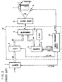
- a memory device 1 stores depth data of each of the pixels in image signals coming from an image read-out device or a computer (not shown in the figure) for one scanning line.
- the depth data are sent to a latcn 2 in the form of pixel depth data DA for every pixel, depending on the position of recording scanning by a pixel clock signal PCLK1 given by a timing treatment circuit 4, which will be described later.
- a pixel clock signal PCLK1 given by a timing treatment circuit 4, which will be described later.
- the pixel depth data DA are 4 bit data.
- a pixel recording pulse signal generation circuit 9 the latch 2 holds (latches) the pixel depth data DA by a pixel clock signal PCLK2 given by the timing treatment circuit 4 and its holding period of time is equal to a period of time during which one pixel domain is scanned for recording.
- These pixel depth data DA held by the latch 2 are given to a comparator 5.
- a counter 3 which is a cyclic 4 bit binary counter, counts clock signals CLK1 coming from a clock generator 10 under the control by a recording scanning signal LINE1 from the timing treatment circuit 4. 16 clock signals CLK1 are outputted for a period of time during which one pixel domain is scanned for recording.
- the counter 3 counts up from “0" (white) to “15” (black) and gives the content of the count as comparison data DB to the comparator 5. At the same time it gives a carry signal as pixel clock signal PCLK3 to the timing treatment circuit 4.
- the timing treatment circuit 4 generates the pixel clock signals PCLK1 and PCLK2, referring to the pixel clock signal PCLK3 and at the same time uses a detection signal LINE2 coming from a laser beam detector 8 as a recording scanning start synchronization signal for every scanning line.
- the comparator 5 compares the pixel depth data DA with the comparison data DB and generates a 2-value pixel recording pulse signal S, corresponding to "black” , if DA > DB "white” , if DA ⁇ DB, which is given to a semiconductor laser circuit 6.
- a laser beam outputted by the semiconductor laser circuit 6 is deflected in a region of an angle ⁇ so as to scan and illuminate an electro-graphic photo-sensitive drum 7. In this way an electro-static latent image is formed and transferred to a recording paper, after having been developed with toner. After that, it is further fixed so as to be a record.
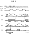
- Figs. 1(A) to 1(C) indicates a timing chart representing the working mode of the pixel recording pulse signal and the pixel recording in such a laser beam printer.
- (A) indicates the pixel number and the pixel depth data DA.
- the abscissa t in (B) represents the time, in which T denotes the period of time necessary for scanning to record one pixel.
- the coordinate represents digital values corresponding to pixel depths, in which "0" indicates “white”; “15” indicates "black”; DA shows the pixel depth data; and DB shows the comparison data.
- the abscissa x in (C) represents the position of the recording scanning of the laser beam and hatched regions show the recorded area for each of the pixels.
- US-4 040 094 describes a video signal processing circuit in which a linear, alternatively increasing and decreasing comparison signal is used instead of the sawtooth-shaped signal DD in Figure 1B.
- this circuit is not suitable for processing colour images without deteriorating the resolution.
- the "pixel” is the smallest unit of spatial resolving power, when an original analogue image is quantized (digitalized) and in general it is defined so as to be sufficiently small.
- a digital printer however, many net points are formed in this pixel and wherever the net points are written in this pixel, no differences therebetween can be recognized by a human eye.
- the movement itself doesn't lower the resolving power.
- the Bayer method is adopted, by which one pixel is represented by many small net points (dots), or a net point is formed at a position deviated from the center of the pixel in order to have a screen angle.
- the net points (dots) of each of the colors formed within one pixel are not concentrated to one point, which is the center of the pixel, contrarily to those in the concentric solution model, but they are suitably arranged within the pixel for every color. In this way superposition of the net points of different colors can be controlled and as the result a high quality full color printing can be effected.
- Figs. 1 (D), (E) and (F), (G) are timing charts illustrating the working mode of the production of the pixel recording pulse signal and the pixel recording for one of the colors.
- (D) shows the working mode of the production of the pixel recording pulse signal using the comparison between pixel depth data DA and comparison data DB, in which the magnitude of the comparison data DB varies so that it increases in the odd pixel number regions and decreases in the even pixel number regions.
- the position of production of the pixel recording pulse signal S generated by comparing the pixel depth data DA with the comparison data is so determined that in the odd pixel number regions the front end of the pixel recording pulse signal is in accordance with the front end of the pertinent pixel and in the even pixel number regions the rear end of the pixel recording pulse signal S is in accordance with the rear end of the pertinent pixel, i.e.
- the pixels No. 2 and No. 3, and No. 4 and No. 5 become continuous. Consequently, in the recording pixels recorded on the basis of this pixel recording pulse signal, as indicated in (E), the pixels No. 2 and No. 3, and No. 4 and No. 5 are continuous, respectively, and thus there are no border portions in the scanning direction between the pixels belonging to each of the pairs. Therefore the unstable region becomes smaller.
- (F) shows an example, where the magnitude of the comparison data DB decreases in the odd pixel number regions and increases in the even pixel number regions.
- the pixels No. 1 and No. 2, and No. 3 and No. 4 are continuous.
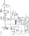
- a counter 13 is a hexadecimal counter, which counts clock signals CLK1 inputted from a clock generator 10 to its clock terminal CLK.
- the recording scanning signal LINE1 outputted by the timing treatment circuit 4 is at the high level during the recording scanning.
- the counter 13 stated above counts the clock signals CLK1, when this recording scanning signal LINE1 inputted to the clear terminal CLR is at the high level and it is cleared to "0", when the signal LINE1 is at the low level.
- the output signal Q 13 of the counter 13 is inputted as it is to an input terminal A of a data selector 14 and the reversed value of the output signal Q 13 is inputted to another input terminal B thereof.
- the counter 13 when the recording scanning signal LINE1 outputted from the timing treatment circuit 4 is at the high level, the counter 13 counts the clock signals CLK1 given by the clock generator 10 and increases the value of the counting output signal Q 13 . When the value of the counting output signal Q 13 reaches "15", a carry signal is produced at the carry terminal Car.
- the comparison data DB which are the output signal Q 15 of the latch 15 increases successively from "0" to "15".
- the comparison data DB repeats its increase and decrease, as indicated in Fig. 1(D), by the fact that such operations are repeated in a period of time, during which the recording scanning signal LINE1 is at the high level.
- Such a comparison data production circuit has an advantage that a high speed operation is possible with respect to the case where the counter 13 counts up and down.
- the comparison data DB varies as indicated in Fig. 1(F) and thus the pixel recording pulse signal S, which effects pixel recording, as indicated in Fig. 1(G), can be obtained.
- the comparison data production circuit indicated in Fig. 4 is provided further with a counter 11 and a monostable multi-vibrator (hereinbelow abbreviated to MM) 16 (block indicated by a broken line). It is possible to vary the screen angle.
- MM monostable multi-vibrator
- the counter 11 is a 2-bit binary counter, in which, when its counting value reaches "3", the carry signal Car becomes high, and screen angle data SD are loaded, when the printing signal PAGE is low.
- the carry signal Car of the counter 11 is low, the FF 12 is preset.
- the data selector 14 selects and outputs the signal at the input A, the initial value of the comparison data DB is "0". To the contrary, when the carry signal Car is high, the FF 12 is cleared. As the result, since the data selector 14 selects and outputs the signal at the input B, the initial value of the comparison data DB is "15".
- the recording scanning signal LINE1 becomes low, the counter 11 counts up.
- the counting value of the counter 11 varies as "0" ⁇ "1", “1” ⁇ "2”
- the carry signal Car since the carry signal Car remains low, when the recording scanning signal LINE1 is changed to the low level and the MM 16 is triggered so that a short pulse signal is produced at its output terminal Q 16 , this pulse signal Q 16 is given to the clear terminal CLR of the FF 12, which is therefore cleared.
- the counting value of the counter 11 varies as "2" ⁇ "3”
- the carry signal Car is changed to the high level and thus the pulse signal Q 16 generated by the MM 16 is given to the preset terminal PR of the FF 12, which is therefore preset.
- the counting value of the counter 11 is "3" and the carry signal Car is at the high level
- the load terminal L of the counter 11 is at the low level
- the following counting value of the counter 11 is screen angle data SD. Consequently, when the screen angle data SD is "3", the FF 12 is preset and when it is not, the FF 12 is reset. This operation is continued as far as the recording is terminated and the printing signal PAGE becomes low.
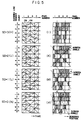
- Figs. 5 (H) - (P) are timing charts showing the operation of production of the pixel recording pulse signal S controlled by this circuit and the pixel recording, in which (H) and (I) represent a case where the screen angle data SD are "3", (H) showing the operation of production of the pixel recording pulse signal, (I) illustrating a pixel recording pattern by means of the pixel recording pulse signal, which is obtained as the result of the operation indicated in (I).
- the abscissa corresponds to the recording scanning direction, where it represents the time in (H) and the scanning position in (I), but it is indicated here by the pixel number.
- the ordinate corresponds to the direction, along which the recording medium is sent, in which it represents the time in (H) and the transfer amount in (I), but it is indicated here by the scanning line number. Further, for the ordinate, the counting value of the counter 11 is written together therewith.
- (J) and (K) show the case where the screen angle data SD are "2"; (L) and (M) the case where the screen angle data SD are "1”; and (N) and (O) the case where the screen angle data SD are "0".
- the FF 12 is preset every time the level of the recording scanning signal LINE1 becomes low. Consequently the initial value of the comparison data DB for every scanning line is "15" and the same operation of production of the pixel recording pulse signal as indicated in Fig.1(F) is repeated.
- the pixel recording pattern for each of the scanning lines based on the pixel recording pulse signal thus obtained is such that the pixels of pixel numbers 1 and 2, and 3 and 4 are continuous, as indicated in Fig. 5(I).
- pixels of pixel numbers 2 and 3, 4 and 5 form pairs and their pixel recording is continuous.
- the pixel recording of the pixels number 1 and 2, 3 and 4 is continuous.
- the recording pulse signal is so produced that the rear end of the recording pulse signal of the preceding recording side pixel in a pair of pixels adjacent to an arbitrarily selected pixel in the recording scanning direction is in accordance with the rear end of the arbitrarily selected pixel and the front end of the recording pulse signal of the succeeding recording side pixel is in accordance with the front end of the arbitrarily selected pixel, production of recording energy is continuous between the pixels of these pairs, that is, the ratio of the areas of the unstable regions stated above can be reduced so that the factor lowering the image quality produced by interruptions of the recording energy and thus lowering of the image quality are alleviated.
- Figs. 3 (C) and (D) are schemes illustrating the principle of 100% UCR.
- Fig. 3(A) indicates a cross-sectional view of a structure, where yellow ink Y, magenta ink M and cyan ink C are printed in this order on a white paper sheet concentrically at a net point so that they are superposed on each other.
- a ⁇ sign in Fig. 3 indicates a boundary between two adjacent pixels.
- Fig. 3(B) indicates the same structure, for which 100% UCR is effected according to the concentric solution motel As indicated in the figure, all the parts, where the three colors, yellow, magenta and cyan are superposed on each other so as to represent black points, are replaced by net points formed by black ink.
- Fig. 3(C) illustrates an example, in which 100% UCR is effected.
- colored dots such as yellow. magenta, cyan, etc. are put to the left within the pixel and only black dots are put to the right.
- the black dots and colored ones are not superposed on each other by calculation of 100% UCR. Consequently there are no colored inks, which have been used in vain under black dots in the concentric solution model and the number of colored inks superposed on each other at a dot is at most 2, what reduces transfer defectives.
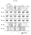
- Fig. 6 shows top views of the surface of the paper sheet for the embodiment of this invention indicated in Fig. 3(D).
- Fig. 3(D) is reproduced at the first line of Fig. 6.
- the first pixel is divided from the left of the pixel into four parts, i.e. a part printed double with cyan ink and yellow ink, a part printed only with cyan ink, a blanc part and a part printed only with black ink. Since the second pixel begins from the left by a black part, the black part of the first pixel and that of the second pixel are jointed together. On the whole it seems that black parts and colored parts are arranged alternately. When this procedure of arrangement is changed also for every line as indicated in the figure, the whole print is equivalent in appearance to a dot printing having a screen angle of 45°.
- the 5-th and 6-th lines in Fig. 6 illustrate a formation of dots, which is closer to the real image.
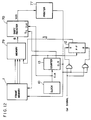
- Fig. 7 is a block diagram showing the construction of a circuit, in which the embodiment of this invention indicated in Fig. 3(D) is applied to a digital printer scanning continuously in the horizontal direction as in a television and Fig. 8 shows schemes for explaining its working mode.
- equivalent or identical items are represented by the same reference numerals as those used for the circuits indicated in Figs. 2 and 4.
- the depth of the data DA allocated to each of the pixels of an image is represented by using e.g. a 3-bit number from "0" to "7". Consequently intermediate tones can be indicated by intermediate values among 8.
- An octal binary counter 13 and a pixel address counter of the frame memory 1, in which pixel data DA are stored, are cleared by the line synchronization signal LINE of a digital printer (e.g. laser beam printer, semiconductor laser printer) 77.
- the flip-flop (hereinbelow abbreviated to FF) 12 is set or preset depending on the phase data Car (cf. Fig.4).
- the counter 13 counts the reference clock CLK coming from a clock oscillator 10 so that its output increases starting from "0".
- the data selector 14 outputs the output of the counter 13 as it is as the comparison data DB, and when it is high, the data selector 14 outputs the reversed value of the output of the counter 13 as the comparison data DB. Consequently, when the output of the FF 12 is low, the comparison data DB increase from “0" to "7” and when it is high, the comparison data DB decreases from "7” to "0".
- the most significant bit MSB of the output of the counter 13 falls.
- the memory 1 outputs the following pixel data and at the same time the FF 12 is reversed. Since the selector 14 reverses the comparison data by the reverse of the FF 12, as the result the comparison data DB begin with "0", when the phase data FD is “low”, and go and return between “0” and “7”. Therefore, they are such that they are indicated in Fig. 8(A). Further, when the FD are “high”, they begin with “7” and go and return between “0” and “7”. Therefore, they are such that they indicated in Fig. 8 (C). On the other hand the pixel data DA outputted by the memory 1 are inputted in the comparator 5, where it is judged which are larger, the inputted pixel data DA or the comparison data DB.
- the most significant bit (MSB) of the pixel data DA is used as a selection signal in the selector 73, which outputs a signal, which is "high” if DA ⁇ DB for the DA from "0" to "3", and if DA ⁇ DB for the DA from "4" to "7"
- this signal is imputted in a printer 77, supposing that a black point is printed, if the VD is high and a white point is printed. if the VD is low, the area ratio S of the black part printed within one pixe! varies as indicated in the following table and intermediate tone printing can be effected.
- phase data is manipulated for every line or for every color, as indicated in Table 2, a printing indicated in Fig. 6 can be effected.
- This circuit needs no memory such as pattern generator, etc. and its construction is simple and fit for high speed operation.
- the number of modulations of the area modulation is 2 n , as indicated in Table 1, it is easy to combine it with the multi-value Dither method or the multi-value depth pattern method.
- Fig. 9 is a scheme for explaining how dots of one of the colors are arranged in pixels (not visible) allocated on the surface of a paper sheet.
- Four types of dot positions, A, B, C and D, are conceivable on the basis of assumptions of a printer.
- Fig. 9 there are five sorts of pixel data, i.e. from “0" to "4", which are depth data allocated to the pixels.
- "0” represents “white” and "4" "black (all over)”.
- "1" - "3" represent half tones between them.
- the dot enlarges, starting from the up and right corner in the pixel, with increasing pixel data.
- the dot enlarges, starting from the up and left corner, the down and left corner and the down and the right corner of the pixel, respectively. Consequently the printer receives the pixel data and information on the type, which are then recorded, as indicated in Fig. 9.
- Fig. 10 indicates information given to the printer for every pixel, in the case where the pixel data and the information thus received are recorded in practice, and Fig. 11 illustrates the recording result.
- the type information indicating the dot position within the pixel is given alternately for every pixel, such as A, B, A, B, ...., for the first line, as indicated in Fig.
- the type information for the first line and that for the second line are given alternately and repeatedly.
- the pixel data arbitrary information of "0" - "4" is allocated to each of the pixels and this figure shows an example thereof.
- the result obtained by recording on a paper sheet is such that it is indicated in Fig. 11, where four dots in four pixels, two adjacent pixels in the vertical direction and two adjacent pixels in the horitzontal direction, are printed, as if they were gathered together at the centre so as to be one point.
- the number of dots is reduced to 1/4 without lowering the resolving power between different pixels. That is, the ratio of area of the unstable region stated above is lowered and the worsening of the image quality is alleviated.
- Fig. 12 is a block diagram illustrating the construction of still another apparatus for realizing the method according to this invention.
- the difference from the apparatus indicated in Fig. 7 consists in that the apparatus indicated in Fig. 12 is constructed by using a look up table memory 79 and a shift register 70 contrarily to that a data selector 14 and a comparator 5 are used in the apparatus indicated in Fig. 7.
- the memory 79 outputs an output pattern on the basis of the pixel data DA sent by the frame memory 1 and in-pixel phase data DFD sent by the flip-flop 12.
- the shift register 70 transforms it witn a high speed by a parallel-serial transformation to form a video signal VDS.
- the look up table is definec as follows. the apparatus works in the completely same manner as the apparatus indicated in Fig. 7.
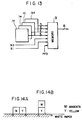
- the look up table memory 79 (see Fig. 13) used in this embodiment receives image data of 12 bits in total from the frame memories 1 y , 1 m , 1 c and 1 b storing yellow, magenta, cyan and black data, respectively, and receives also selection signals S 0 , S 1 for selecting necessary video signals and in-pixel phase data PFD, which can be expanded so that an optimum in-pixel net point arrangement can be calculated.
- selection signals S 0 , S 1 for selecting necessary video signals and in-pixel phase data PFD, which can be expanded so that an optimum in-pixel net point arrangement can be calculated.
- the position of the dot in each of the pixels can be set arbitrarily, applications as indicated below are conceivable.
- Net point printing expresses, in general, colors by addition color mixing and subtraction color mixing and in general, their ratio cannot be determined unequivocally, even when a same color is expressed.
- red having a reduced chromaticity it can be obtained not by superposing two colors but by juxaposing them, as indicated in Fig. 14A, where magenta is put in the left half and yellow is put in the right half.
- magenta and yellow in the left half region.
- the former represents an addition color mixing of magenta and yellow
- the latter represents a subtraction color mixing of magenta and yellow.
- an intermediate color mixing between them can be conceived.
Landscapes
- Engineering & Computer Science (AREA)
- Multimedia (AREA)
- Signal Processing (AREA)
- Fax Reproducing Arrangements (AREA)
- Dot-Matrix Printers And Others (AREA)
Claims (5)
- Procédé d'impression par faisceau laser par balayage pour enregistrer une image multicolore, selon lequel l'intensité d'une couleur d'un élément d'image est reproduite en sélectionnant la dimension d'un point à enregistrer à l'intérieur de l'élément d'image respectif et ayant cette couleur comprenant les étapes suivantes :a) on enregistre un premier point d'une première couleur dans une ligne de balayage à l'intérieur d'un premier élément d'image à la limite entre le premier élément d'image et un second élément d'image dans ladite ligne de balayage ;b) on enregistre un second point de ladite première couleur à l'intérieur du second élément d'image adjacent audit premier point ;c) on enregistre un troisième point d'une seconde couleur dans ledit premier élément d'image pour s'étendre depuis un bord dudit premier élément d'image, lequel bord est différent de ladite limite précitée, vers le centre dudit premier élément d'image ;d) on enregistre un quatrième point de ladite seconde couleur à l'intérieur dudit second élément d'image pour s'étendre depuis un bord dudit second élément d'image, lequel bord est différent de ladite limite précitée, vers le centre dudit second élément d'image ; ete) on répète les étapes (a) à (d) pour d'autres paires de tels premier et second éléments d'image de façon que les premier et second éléments d'image soient disposés en alternance dans ladite ligne de balayage et dans d'autres lignes de balayage successives.
- Procédé selon la revendication 1, dans lequel ladite première couleur est formée par une structure à couches multiples constituée d'une encre jaune, d'une encre magenta et d'une encre cyan, et ladite seconde couleur est formée par une encre noire.
- Procédé selon la revendication 1 ou 2, dans lequel des données de profondeur (DA) de chaque élément d'image dans un signal d'image sont transformées en un signal d'impulsion d'enregistrement d'image (S) possédant une durée proportionnelle à la profondeur pour chacun des éléments d'image et commandant l'énergie d'enregistrement de manière à produire lesdits points.
- Dispositif d'impression par faisceau laser de type à balayage comportant :un moyen formant mémoire (1) mémorisant des signaux de données de profondeur (DA) pour une ligne de balayage,un moyen (10, 12, 13, 14, 15) comprenant un générateur d'horloge (10) et un compteur (13) et délivrant un signal de données de comparaison (DB) formé en répétant une opération de comptage et une opération de décomptage pour chaque élément d'image,un moyen (5, 9) comparant lesdites données de profondeur (DA) audit signal de données de comparaison (DB) et générant ainsi un signal de pulsion d'enregistrement d'élément d'image (S) ; etun moyen de synchronisation (4) commandant le fonctionnement desdits moyens formant mémoire (1), desdits moyens de formation de données de comparaison (10, 12, 13, 14, 15) et desdits moyens de formation du signal d'impulsion d'enregistrement d'élément d'image (5, 9), de sorte que :un premier point d'une première couleur est enregistré à l'intérieur d'un premier élément d'image à la limite du premier élément d'image et d'un second élément d'image dans ladite ligne de balayage,un second point de ladite première couleur est enregistré à l'intérieur dudit second élément d'image adjacent audit premier point,un troisième point d'une seconde couleur est enregistré dans ledit premier élément d'image et s'étend depuis un bord dudit premier élément d'image différent de ladite limite précitée vers le centre dudit premier élément d'image, etun quatrième point de ladite seconde couleur est enregistré à l'intérieur dudit second élément d'image et s'étend depuis un bord dudit second élément d'image, lequel bord est différent de ladite limite précitée, vers le centre dudit second élément d'image, et d'autres paires de tels premiers et seconds éléments d'image sont enregistrées de façon que les premiers et seconds éléments d'image soient disposés en alternance dans ladite ligne de balayage et dans d'autres lignes de balayage successives.
- Dispositif selon la revendication 4, comportant en outre un compteur (11) alimenté par un signal d'horloge de ligne de balayage, dont le signal de sortie commande lesdits moyens (10, 12, 13, 14, 15) pour délivrer ledit signal de données de comparaison (DB) pour modifier la phase dudit signal de données de comparaison (DB) après un nombre prédéterminé de lignes de manière à commander l'angle d'écran.
Applications Claiming Priority (4)
| Application Number | Priority Date | Filing Date | Title |
|---|---|---|---|
| JP60064966A JPS61225971A (ja) | 1985-03-30 | 1985-03-30 | 画素記録パルス信号発生方法 |
| JP64966/85 | 1985-03-30 | ||
| JP184274/85 | 1985-08-23 | ||
| JP60184274A JPH0636556B2 (ja) | 1985-08-23 | 1985-08-23 | カラ−印刷方法 |
Publications (4)
| Publication Number | Publication Date |
|---|---|
| EP0204094A2 EP0204094A2 (fr) | 1986-12-10 |
| EP0204094A3 EP0204094A3 (en) | 1988-05-25 |
| EP0204094B1 EP0204094B1 (fr) | 1993-07-21 |
| EP0204094B2 true EP0204094B2 (fr) | 1998-08-19 |
Family
ID=26406114
Family Applications (1)
| Application Number | Title | Priority Date | Filing Date |
|---|---|---|---|
| EP86104403A Expired - Lifetime EP0204094B2 (fr) | 1985-03-30 | 1986-04-01 | Procédé d'impression du type d'enregistrement par balayage et appareil pour le mettre en oeuvre |
Country Status (3)
| Country | Link |
|---|---|
| US (2) | US4926248A (fr) |
| EP (1) | EP0204094B2 (fr) |
| DE (2) | DE3688715T3 (fr) |
Families Citing this family (48)
| Publication number | Priority date | Publication date | Assignee | Title |
|---|---|---|---|---|
| US4800442A (en) | 1985-08-15 | 1989-01-24 | Canon Kabushiki Kaisha | Apparatus for generating an image from a digital video signal |
| DE3689216T2 (de) * | 1985-08-20 | 1994-03-03 | Canon Kk | Bildverarbeitungsgerät. |
| US5175635A (en) * | 1986-06-02 | 1992-12-29 | Kabushiki Kaisha Toshiba | Picture printing apparatus using multivalued patterns, binary patterns and dither patterns selectively |
| DE68927970T2 (de) * | 1988-09-08 | 1997-10-09 | Canon Kk | Punktbilddatenausgabegerät |
| US7382929B2 (en) * | 1989-05-22 | 2008-06-03 | Pixel Instruments Corporation | Spatial scan replication circuit |
| US5111217A (en) * | 1989-12-18 | 1992-05-05 | Eastman Kodak Company | Dot printer and method for grey level recording |
| EP0959615B1 (fr) * | 1990-01-19 | 2005-03-16 | Canon Kabushiki Kaisha | Appareil de traitement d'images en couleur |
| US5109283A (en) * | 1990-03-02 | 1992-04-28 | Xerographic Laser Images Corporation | Raster scanning engine driver which independently locates engine drive signal transistors within each cell area |
| US5122883A (en) * | 1990-03-02 | 1992-06-16 | Xerographic Laser Images Corporation | Raster scanning engine driver which independently locates engine drive signal transitions within each pixel |
| DE69129675T2 (de) * | 1990-04-25 | 1999-01-07 | Canon K.K., Tokio/Tokyo | Bildverarbeitungsvorrichtung |
| US5272544A (en) * | 1990-05-29 | 1993-12-21 | Canon Kabushiki Kaisha | Digital/analog converter and image processing apparatus using the same |
| US5264926A (en) * | 1990-09-14 | 1993-11-23 | Minnesota Mining And Manufacturing Company | Perpendicular, equal frequency non-conventional screen patterns for electronic halftone generation |
| US5253084A (en) * | 1990-09-14 | 1993-10-12 | Minnesota Mining And Manufacturing Company | General kernel function for electronic halftone generation |
| US5583660A (en) * | 1990-09-14 | 1996-12-10 | Minnesota Mining And Manufacturing Company | Non-perpendicular, equal frequency non-conventional screen patterns for electronic halftone generation |
| US5323245A (en) * | 1990-09-14 | 1994-06-21 | Minnesota Mining And Manufacturing Company | Perpendicular, unequal frequency non-conventional screen patterns for electronic halftone generation |
| US5258832A (en) * | 1990-09-14 | 1993-11-02 | Minnesota Mining And Manufacturing Company | Non-perpendicular, unequal frequency non-conventional screen patterns for electronic halftone generation |
| DE69130791T2 (de) * | 1990-10-03 | 1999-07-08 | Canon K.K., Tokio/Tokyo | Abbildungsgerät |
| JP3176083B2 (ja) * | 1991-05-20 | 2001-06-11 | キヤノン株式会社 | 画像処理装置及びその方法 |
| DE69122382T2 (de) * | 1991-06-24 | 1997-04-03 | Agfa Gevaert Nv | Parallel-Serie-Umwandlung von Informationsdaten |
| US5367381A (en) * | 1991-07-29 | 1994-11-22 | Xerox Corporation | Method and apparatus for enhanced resolution and contrast via super intensity controlled overscanned illumination in a two dimensional high addressability printer |
| US5357273A (en) * | 1991-07-29 | 1994-10-18 | Xerox Corporation | Resolution conversion via intensity controlled overscanned illumination for optical printers and the like having high gamma photosensitive recording media |
| US5309246A (en) * | 1991-09-18 | 1994-05-03 | Eastman Kodak Company | Technique for generating additional colors in a halftone color image through use of overlaid primary colored halftone dots of varying size |
| JP3246754B2 (ja) * | 1991-09-20 | 2002-01-15 | 株式会社日立製作所 | 光記録装置及び情報処理システム |
| US6262809B1 (en) | 1991-12-27 | 2001-07-17 | Minolta Co., Ltd. | Image processing apparatus shifting image data between adjacent picture elements |
| EP0564868A3 (en) * | 1992-04-06 | 1993-11-10 | Konishiroku Photo Ind | Image forming apparatus |
| WO1993022871A1 (fr) * | 1992-05-06 | 1993-11-11 | Microsoft Corporation | Procede et systeme de reproduction de demi-teintes en couleur |
| US5274472A (en) * | 1992-05-21 | 1993-12-28 | Xerox Corporation | High addressability image generator using pseudo interpolation of video and screen data |
| JPH06155815A (ja) * | 1992-11-18 | 1994-06-03 | Konica Corp | 画像形成装置 |
| US5493323A (en) * | 1993-08-05 | 1996-02-20 | Xerox Corporation | Color images having multiple separations with minimally overlapping halftone dots |
| EP0652671A3 (fr) * | 1993-11-05 | 1995-06-21 | Ibm | Conversion d'images numériques en couleurs. |
| DE69433608T2 (de) * | 1993-12-27 | 2005-02-17 | Sharp K.K. | Verfahren zur Gradationssteuerung und Verbesserung der Bildqualität bei einem Thermodrucker |
| WO1997035423A1 (fr) * | 1996-03-22 | 1997-09-25 | Minnesota Mining And Manufacturing Company | Procede de codage de donnees d'image pour imagerie polychrome |
| US6025865A (en) * | 1996-09-10 | 2000-02-15 | Mitsubishi Chemical America | Variable color intensity laser printing |
| US6097502A (en) * | 1996-12-18 | 2000-08-01 | Seiko Epson Corporation | Multilevel screening for color laser printer |
| JP3244081B2 (ja) * | 1999-02-25 | 2002-01-07 | セイコーエプソン株式会社 | 電子写真装置及び電子写真の画像処理方法 |
| US6633412B1 (en) | 1999-03-26 | 2003-10-14 | Seiko Epson Corporation | Smoothness enhancement in laser printing through periodic modulation of halftone cell |
| JP3589286B2 (ja) * | 1999-08-23 | 2004-11-17 | セイコーエプソン株式会社 | 画像処理装置及びその方法、並びにその画像処理装置を備えたプリンタシステム |
| US7072072B1 (en) * | 2000-05-02 | 2006-07-04 | Xerox Corporation | Color rendering optimized for text and line art |
| US7031025B1 (en) | 2000-08-23 | 2006-04-18 | Hewlett-Packard Development Company, L.P. | Combined dot density and dot size modulation |
| US6999202B2 (en) * | 2001-03-27 | 2006-02-14 | Polaroid Corporation | Method for generating a halftone of a source image |
| US6937365B2 (en) | 2001-05-30 | 2005-08-30 | Polaroid Corporation | Rendering images utilizing adaptive error diffusion |
| US6842186B2 (en) | 2001-05-30 | 2005-01-11 | Polaroid Corporation | High speed photo-printing apparatus |
| US6906736B2 (en) | 2002-02-19 | 2005-06-14 | Polaroid Corporation | Technique for printing a color image |
| US7283666B2 (en) | 2003-02-27 | 2007-10-16 | Saquib Suhail S | Digital image exposure correction |
| US20040207890A1 (en) * | 2003-04-16 | 2004-10-21 | Breswick Curt Paul | Method and apparatus for controlling shifting of data out of at least one image sensor |
| US8773685B2 (en) | 2003-07-01 | 2014-07-08 | Intellectual Ventures I Llc | High-speed digital image printing system |
| US20090066776A1 (en) * | 2005-11-02 | 2009-03-12 | Dai Nippon Printing Co., Ltd. | Thermal recording apparatus, image forming method, and printed object |
| US20090021545A1 (en) * | 2007-07-19 | 2009-01-22 | Samsung Electronics Co. Ltd. | Image forming apparatus and method of generating output signal thereof |
Family Cites Families (29)
| Publication number | Priority date | Publication date | Assignee | Title |
|---|---|---|---|---|
| NL299203A (fr) * | 1962-07-02 | |||
| JPS4923645A (fr) | 1972-06-21 | 1974-03-02 | ||
| US4040094A (en) * | 1973-02-13 | 1977-08-02 | International Publishing Corporation Ltd. | Electronic screening |
| GB1448112A (en) * | 1973-02-13 | 1976-09-02 | Int Publishing Corp Ltd | Electronic screening |
| JPS5255642A (en) | 1975-10-31 | 1977-05-07 | Matsushita Graphic Communic | Recorder |
| US4149183A (en) * | 1976-05-21 | 1979-04-10 | Xerox Corporation | Electronic halftone generator |
| GB1604904A (en) | 1977-05-18 | 1981-12-16 | Raychem Corp | Electrical devices and heating method |
| JPS54144201A (en) | 1978-04-29 | 1979-11-10 | Gakken Co Ltd | Halfftone image signal generator |
| JPS56153331A (en) * | 1980-04-30 | 1981-11-27 | Fuji Photo Film Co Ltd | Laser recorder |
| JPS5717265A (en) | 1980-07-07 | 1982-01-28 | Toshiba Corp | Facsimile recording and control system |
| JPS5757679A (en) * | 1980-09-24 | 1982-04-06 | Canon Inc | Device for driving thermal head |
| JPS5764565A (en) | 1980-10-09 | 1982-04-19 | Canon Inc | Digital color pinter |
| JPS5799866A (en) * | 1980-12-15 | 1982-06-21 | Canon Inc | Picture image binary-coding method |
| US4498108A (en) * | 1980-12-29 | 1985-02-05 | Dr.-Ing. Rudolf Hell Gmbh | Screen for reproducing continuous-tone pictures |
| JPS57171337A (en) * | 1981-04-14 | 1982-10-21 | Dainippon Screen Mfg Co Ltd | Production of halftone plate picture |
| US4499489A (en) | 1981-06-08 | 1985-02-12 | Dr. Ing. Rudolf Hell Gmbh | Production of screen printing blocks |
| JPS5811941A (ja) * | 1981-07-16 | 1983-01-22 | Dainippon Screen Mfg Co Ltd | 網目版画像記録装置における絵柄信号と文字信号の処理方法 |
| JPS5814669A (ja) | 1981-07-20 | 1983-01-27 | Fuji Photo Film Co Ltd | 網目画像信号作成方法 |
| JPS5856572A (ja) * | 1981-09-30 | 1983-04-04 | Nippon Telegr & Teleph Corp <Ntt> | カラ−再現方法 |
| US4507685A (en) * | 1982-06-25 | 1985-03-26 | Canon Kabushiki Kaisha | Image recording device |
| JPS5968245A (ja) * | 1982-10-13 | 1984-04-18 | Ricoh Co Ltd | 多色インクジエツト記録方法 |
| DE3338722A1 (de) * | 1982-10-26 | 1984-05-03 | Victor Company Of Japan, Ltd., Yokohama, Kanagawa | Tintenuebertragungs-thermodrucker mit hohem aufloesungsvermoegen |
| JPS5977769A (ja) * | 1982-10-27 | 1984-05-04 | Canon Inc | 像再生装置 |
| US4683492A (en) * | 1983-03-08 | 1987-07-28 | Canon Kabushiki Kaisha | Method and apparatus for recording a full-color image with a plurality of colorants on the basis of a set of area factors for the colorants selected from a plurality of sets of area factors calculated from a plurality of sets of equations |
| US4680646A (en) * | 1983-09-05 | 1987-07-14 | Canon Kabushiki Kaisha | Image forming device for reproducing a half-tone image |
| JPS60145769A (ja) * | 1984-01-09 | 1985-08-01 | Ricoh Co Ltd | 多色連続階調画の表現方法 |
| JPH0737138B2 (ja) * | 1984-02-20 | 1995-04-26 | キヤノン株式会社 | カラー画像形成装置 |
| US4680625A (en) * | 1984-07-18 | 1987-07-14 | Konishiroku Photo Industry Co., Ltd. | Method and apparatus for multicolor image forming |
| US4800442A (en) * | 1985-08-15 | 1989-01-24 | Canon Kabushiki Kaisha | Apparatus for generating an image from a digital video signal |
-
1986
- 1986-04-01 DE DE3688715T patent/DE3688715T3/de not_active Expired - Lifetime
- 1986-04-01 EP EP86104403A patent/EP0204094B2/fr not_active Expired - Lifetime
- 1986-04-01 DE DE8686104403A patent/DE3688715D1/de not_active Expired - Lifetime
-
1988
- 1988-08-23 US US07/235,096 patent/US4926248A/en not_active Ceased
-
1997
- 1997-01-22 US US08/787,569 patent/USRE38235E1/en not_active Expired - Lifetime
Also Published As
| Publication number | Publication date |
|---|---|
| DE3688715D1 (de) | 1993-08-26 |
| USRE38235E1 (en) | 2003-08-26 |
| DE3688715T2 (de) | 1993-10-28 |
| EP0204094A2 (fr) | 1986-12-10 |
| DE3688715T3 (de) | 1999-05-06 |
| DE3688715T4 (de) | 1995-08-10 |
| US4926248A (en) | 1990-05-15 |
| EP0204094A3 (en) | 1988-05-25 |
| EP0204094B1 (fr) | 1993-07-21 |
Similar Documents
| Publication | Publication Date | Title |
|---|---|---|
| EP0204094B2 (fr) | Procédé d'impression du type d'enregistrement par balayage et appareil pour le mettre en oeuvre | |
| US5903713A (en) | Moire free multilevel halftoning of color images | |
| EP0525520B1 (fr) | Système de tramage et de reproduction en couleurs pour l'impression offset | |
| US4980757A (en) | Image processing apparatus for gradation processing of an image signal to output a pulse width modulated signal | |
| EP0717551B1 (fr) | Dispositif de traitement d'image | |
| US5712929A (en) | Image processing apparatus | |
| US5463471A (en) | Method and system of color halftone reproduction | |
| EP0680195A1 (fr) | Obtention de demi-teintes à niveaux multiples et à points et lignes groupés pour l'impression électrographique en couleurs | |
| US6081349A (en) | Image processing device, image processing system, and method for generating screens for image processing | |
| JPS6242668A (ja) | 画像処理装置 | |
| JPH0359623B2 (fr) | ||
| JPS58173973A (ja) | 画像処理装置 | |
| JP2800117B2 (ja) | 画像形成装置 | |
| JP2003305883A (ja) | 画像形成装置 | |
| JPS6245282A (ja) | カラ−印刷方法 | |
| US5666444A (en) | Image processing apparatus | |
| JPS6242693A (ja) | 画像処理装置 | |
| JPS62284574A (ja) | 画像記録装置 | |
| JP3984693B2 (ja) | 画像処理装置及び方法 | |
| JPH05169720A (ja) | カラー画像形成装置 | |
| JP2568055B2 (ja) | 画素記録パルス信号発生装置 | |
| JPH08163361A (ja) | 画像の2値化方法および装置 | |
| JPS6291076A (ja) | 画像情報出力方式 | |
| JPH027667A (ja) | 画像処理装置 | |
| JPS61107873A (ja) | カラ−中間調画像処理方法 |
Legal Events
| Date | Code | Title | Description |
|---|---|---|---|
| PUAI | Public reference made under article 153(3) epc to a published international application that has entered the european phase |
Free format text: ORIGINAL CODE: 0009012 |
|
| AK | Designated contracting states |
Kind code of ref document: A2 Designated state(s): DE GB IT NL |
|
| PUAL | Search report despatched |
Free format text: ORIGINAL CODE: 0009013 |
|
| AK | Designated contracting states |
Kind code of ref document: A3 Designated state(s): DE GB IT NL |
|
| 17P | Request for examination filed |
Effective date: 19881028 |
|
| 17Q | First examination report despatched |
Effective date: 19900905 |
|
| GRAA | (expected) grant |
Free format text: ORIGINAL CODE: 0009210 |
|
| AK | Designated contracting states |
Kind code of ref document: B1 Designated state(s): DE GB IT NL |
|
| REF | Corresponds to: |
Ref document number: 3688715 Country of ref document: DE Date of ref document: 19930826 |
|
| ITF | It: translation for a ep patent filed | ||
| PLBI | Opposition filed |
Free format text: ORIGINAL CODE: 0009260 |
|
| 26 | Opposition filed |
Opponent name: ARMATUREN- UND APPARATEBAU FRANZ SCHUCK GMBH Effective date: 19940420 |
|
| NLR1 | Nl: opposition has been filed with the epo |
Opponent name: ARMATUREN- UND APPARATEBAU FRANZ SCHUCK GMBH |
|
| APAC | Appeal dossier modified |
Free format text: ORIGINAL CODE: EPIDOS NOAPO |
|
| APAE | Appeal reference modified |
Free format text: ORIGINAL CODE: EPIDOS REFNO |
|
| APCC | Communication from the board of appeal sent |
Free format text: ORIGINAL CODE: EPIDOS OBAPO |
|
| APAC | Appeal dossier modified |
Free format text: ORIGINAL CODE: EPIDOS NOAPO |
|
| PLAW | Interlocutory decision in opposition |
Free format text: ORIGINAL CODE: EPIDOS IDOP |
|
| PLAW | Interlocutory decision in opposition |
Free format text: ORIGINAL CODE: EPIDOS IDOP |
|
| PUAH | Patent maintained in amended form |
Free format text: ORIGINAL CODE: 0009272 |
|
| STAA | Information on the status of an ep patent application or granted ep patent |
Free format text: STATUS: PATENT MAINTAINED AS AMENDED |
|
| 27A | Patent maintained in amended form |
Effective date: 19980819 |
|
| AK | Designated contracting states |
Kind code of ref document: B2 Designated state(s): DE GB IT NL |
|
| NLR2 | Nl: decision of opposition | ||
| NLR3 | Nl: receipt of modified translations in the netherlands language after an opposition procedure | ||
| REG | Reference to a national code |
Ref country code: GB Ref legal event code: IF02 |
|
| PGFP | Annual fee paid to national office [announced via postgrant information from national office to epo] |
Ref country code: NL Payment date: 20020403 Year of fee payment: 17 |
|
| PG25 | Lapsed in a contracting state [announced via postgrant information from national office to epo] |
Ref country code: NL Free format text: LAPSE BECAUSE OF NON-PAYMENT OF DUE FEES Effective date: 20031101 |
|
| NLV4 | Nl: lapsed or anulled due to non-payment of the annual fee |
Effective date: 20031101 |
|
| PGFP | Annual fee paid to national office [announced via postgrant information from national office to epo] |
Ref country code: GB Payment date: 20050324 Year of fee payment: 20 |
|
| PG25 | Lapsed in a contracting state [announced via postgrant information from national office to epo] |
Ref country code: IT Free format text: LAPSE BECAUSE OF NON-PAYMENT OF DUE FEES;WARNING: LAPSES OF ITALIAN PATENTS WITH EFFECTIVE DATE BEFORE 2007 MAY HAVE OCCURRED AT ANY TIME BEFORE 2007. THE CORRECT EFFECTIVE DATE MAY BE DIFFERENT FROM THE ONE RECORDED. Effective date: 20050401 |
|
| PGFP | Annual fee paid to national office [announced via postgrant information from national office to epo] |
Ref country code: DE Payment date: 20050609 Year of fee payment: 20 |
|
| REG | Reference to a national code |
Ref country code: GB Ref legal event code: 732E |
|
| APAH | Appeal reference modified |
Free format text: ORIGINAL CODE: EPIDOSCREFNO |
|
| PG25 | Lapsed in a contracting state [announced via postgrant information from national office to epo] |
Ref country code: GB Free format text: LAPSE BECAUSE OF EXPIRATION OF PROTECTION Effective date: 20060331 |
|
| REG | Reference to a national code |
Ref country code: GB Ref legal event code: PE20 |