EP0204646A1 - Canal d'alimentation en eau d'une turbine KAPLAN à axe vertical - Google Patents
Canal d'alimentation en eau d'une turbine KAPLAN à axe vertical Download PDFInfo
- Publication number
- EP0204646A1 EP0204646A1 EP86420143A EP86420143A EP0204646A1 EP 0204646 A1 EP0204646 A1 EP 0204646A1 EP 86420143 A EP86420143 A EP 86420143A EP 86420143 A EP86420143 A EP 86420143A EP 0204646 A1 EP0204646 A1 EP 0204646A1
- Authority
- EP
- European Patent Office
- Prior art keywords
- turbine
- downstream
- channel
- water
- shaft
- Prior art date
- Legal status (The legal status is an assumption and is not a legal conclusion. Google has not performed a legal analysis and makes no representation as to the accuracy of the status listed.)
- Granted
Links
- XLYOFNOQVPJJNP-UHFFFAOYSA-N water Substances O XLYOFNOQVPJJNP-UHFFFAOYSA-N 0.000 claims description 17
- 238000011144 upstream manufacturing Methods 0.000 claims description 4
- 230000015572 biosynthetic process Effects 0.000 claims description 3
- 238000000926 separation method Methods 0.000 description 3
- 240000008042 Zea mays Species 0.000 description 2
- 238000009434 installation Methods 0.000 description 1
- 239000007788 liquid Substances 0.000 description 1
- 238000004519 manufacturing process Methods 0.000 description 1
Images

Classifications
-
- F—MECHANICAL ENGINEERING; LIGHTING; HEATING; WEAPONS; BLASTING
- F03—MACHINES OR ENGINES FOR LIQUIDS; WIND, SPRING, OR WEIGHT MOTORS; PRODUCING MECHANICAL POWER OR A REACTIVE PROPULSIVE THRUST, NOT OTHERWISE PROVIDED FOR
- F03B—MACHINES OR ENGINES FOR LIQUIDS
- F03B13/00—Adaptations of machines or engines for special use; Combinations of machines or engines with driving or driven apparatus; Power stations or aggregates
- F03B13/08—Machine or engine aggregates in dams or the like; Conduits therefor, e.g. diffusors
-
- Y—GENERAL TAGGING OF NEW TECHNOLOGICAL DEVELOPMENTS; GENERAL TAGGING OF CROSS-SECTIONAL TECHNOLOGIES SPANNING OVER SEVERAL SECTIONS OF THE IPC; TECHNICAL SUBJECTS COVERED BY FORMER USPC CROSS-REFERENCE ART COLLECTIONS [XRACs] AND DIGESTS
- Y02—TECHNOLOGIES OR APPLICATIONS FOR MITIGATION OR ADAPTATION AGAINST CLIMATE CHANGE
- Y02E—REDUCTION OF GREENHOUSE GAS [GHG] EMISSIONS, RELATED TO ENERGY GENERATION, TRANSMISSION OR DISTRIBUTION
- Y02E10/00—Energy generation through renewable energy sources
- Y02E10/20—Hydro energy
Definitions
- the present invention relates to a low-drop hydraulic turbine of the Kaplan type with a vertical axis.
- Kaplan turbines with vertical axis are used, the supply of which is carried out by means of a water chamber, that is to say a channel for bringing it to the open air or under load.
- a frustoconical distributor converging downstream is also used in the usual way, that is to say in this case downwards.
- the improvements which are the subject of the present invention aim to remedy the two aforementioned drawbacks and to allow the production of a supply channel for a Kaplan turbine with vertical axis which on the one hand removes dead water zones of said channel, and on the other hand prevents the formation of suction vortices.
- the vertical side walls of the feed channel established in accordance with the invention are oriented in a convergent manner, so that, in line with the turbine, the width of said channel is slightly greater than the diameter of the distributor located above the turbine; in addition, means are provided in the channel and downstream of the turbine in order to prevent the development of suction vortices downstream of its shaft.
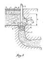
- Fig. 1 schematically illustrates a hydraulic installation for a Kaplan turbine with a vertical axis. It is observed that the turbine 1 wedged at the lower end of a vertical shaft mounted in a sheath 2 is placed below a distributor with a frustoconical wall 3 comprising guide fins 4 connecting the wall of the distributor to the sheath 2 of the turbine shaft 1.
- the water supply to the turbine 1 is achieved by means of a channel 5 with a free surface, the top of which is closed by slabs 6. It is observed that the upstream free surface referenced 7 of the liquid in the supply channel is well below the tiles 6.
- the vertical side walls 5a and 5b of the channel 5 are oriented convergently in the direction of the vertical plane of symmetry of said channel, so that they come to connect with the rounded end face 5c of this channel, which has a diameter slightly greater than the outer diameter D of the guide fins 4.
- the dead water zones of the usual water chambers favor the development of vortices where are likely to create them themselves.
- the walls 5a, 5b of the channel 5 make it possible to eliminate the zones of dead water and their drawbacks with regard to the vortexes.
- channel 5 is a load conduit 8 such as that illustrated in FIG. 3, it is possible to assign to its vertical side walls located in the region of the turbine convergent orientations such as those illustrated in FIG. 2.
- the separation of the flow can be eliminated by three kinds of means.
- the sleeve 2 of the shaft of said turbine can be profiled so as to give it, in cross section, an aerodynamic ovoid shape.
- This raft would screen between the open air located above the surface 7 of the water and the latter, so as to break the vortices at the moment when they develop.
- the device chosen to eliminate the suction vortices downstream of the turbine is produced by means of a fixed wall or mask 9 inclined downwards from upstream to downstream and located downstream of the sheath 2 of the turbine shaft.
Landscapes
- Engineering & Computer Science (AREA)
- Chemical & Material Sciences (AREA)
- Combustion & Propulsion (AREA)
- Mechanical Engineering (AREA)
- General Engineering & Computer Science (AREA)
- Hydraulic Turbines (AREA)
Abstract
Description
- La présente invention est relative à une turbine hydraulique de basse chute du genre Kaplan à axe vertical.
- Dans le cas de basse chute, c'est-à-dire dont les hauteurs sont comprises de manière générale entre quelques mètres et quelques dizaines de mètres, on utilise des turbines Kaplan à axe vertical dont l'alimentation est réalisée au moyen d'une chambre d'eau, c'est-à-dire d'un canal d'amenée à l'air libre ou en charge. On utilise aussi de manière usuelle un distributeur tronconique convergent vers l'aval, c'est-à-dire dans ce cas vers le bas.
- Toutefois, les essais sur modèles réduits ont mis en évidence des phénomènes perturbateurs :
- C'est ainsi que dans -ne chambre d'eau, il existe des zones d'eau morte qui favorisent le développement des tourbillons apparaissant dans d'autres points de ladite chambre d'eau, mais ces zones d'eau morte peuvent elles-mêmes également donner naissance à des vortex.
- En outre, en aval de l'arbre de ladite turbine ou de son fourreau circulaire, il se produit un décollement de l'écoulement de l'eau avec apparition de vortex. Ceux-ci grossissent en entraînant de l'air en dessous de la surface libre de telle sorte que les vortex se transforment en tourbillons aspirants.
- Les perfectionnements qui font l'objet de la présente invention visent à remédier aux deux inconvénients précités et à permettre la réalisation d'un canal d'alimentation d'une turbine Kaplan à axe vertical qui d'une part supprime les zones d'eau morte dudit canal, et d'autre part évite la formation de tourbillons aspirants.
- A cet effet, les parois latérales verticales du canal d'alimentation établi conformément à l'invention sont orientées de manière convergente, afin qu'au droit de la turbine, la largeur dudit canal soit un peu supérieure au diamètre du distributeur situé au-dessus de la turbine ; en outre, des moyens sont prévus dans le canal et en aval de la turbine en vue d'empêcher le développement de tourbillons aspirants en aval de son arbre.
- Le dessin annexé, donné à titre d'exemple, permettra de mieux comprendre l'invention, les caractéristiques qu'elle présente et les avantages qu'elle est susceptible de procurer :
- Fig. 1 illustre en coupe verticale une turbine Kaplan à axe vertical, alimentée par une chambre d'eau comportant application des perfectionnements suivant l'invention.
- Fig. 2 en est une coupe suivant II-II (fig. 1).
- Fig. 3 est une vue semblable à celle de fig. 1, mais illustrant une alimentation par un conduit en charge à la place d'une chambre d'eau.
- Fig. 1 illustre schématiquement une installation hydraulique pour une turbine Kaplan à axe vertical. On observe que la turbine 1 calée à l'extrémité inférieure d'un arbre vertical monté dans un fourreau 2 est placée en dessous d'un distributeur à paroi tronconique 3 comportant des ailettes directrices 4 reliant la paroi du distributeur au fourreau 2 de l'arbre de la turbine 1.
- L'alimentation en eau de la turbine 1 est réalisée au moyen d'un canal 5 à surface libre dont le dessus est fermé par des dalles 6. On observe que la surface libre amont référencée 7 du liquide dans le canal d'amenée se trouve bien en dessous des dalles 6.
- Conformément à l'invention et comme illustré en fig. 2, les parois latérales verticales 5a et 5b du canal 5 sont orientées de manière convergente en direction du plan vertical de symétrie dudit canal, de manière qu'elles viennent se raccorder avec la face extrême arrondie 5c de ce canal, laquelle comporte un diamètre un peu supérieur au diamètre extérieur D des ailettes directrices 4.
- Comme indiqué plus haut, les zones d'eau morte des chambres d'eau usuelles favorisent le développement de vortex où sont susceptibles d'en créer elles-mêmes. Au contraire, grâce à leur forme convergente dans la zone de la turbine, les parois 5a, 5b du canal 5 permettent d'éliminer les zones d'eau morte et leurs inconvénients en ce qui concerne les vortex.
- Il va de soi que si le canal 5 est un conduit en charge 8 tel que celui illustré en fig. 3, on peut affecter à ses parois latérales verticales situées dans la zone de la turbine des orientations convergentes telles que celles illustrées en fig. 2.
- En cas de surface libre, en aval du fourreau 2 de l'arbre de la turbine 1, il se produit un décollement de l'écoulement avec apparition de vortex qui, en grossissant entraînent de l'air situé au-dessus de la surface libre 7 de l'eau du canal 5. Les vortex en question se transforment alors en tourbillons aspirants. Ces tourbillons sont sources de vibrations et d'instabilité de fonctionnement.
- Conformément à l'invention, on peut supprimer le décollement de l'écoulement par trois sortes de moyens.
- Tout d'abord, on peut profiler le fourreau 2 de l'arbre de ladite turbine de manière à lui conférer en section transversale une forme aérodynamique ovoïde.
- On pourrait aussi prévoir un radeau flottant dans le compartiment du canal à l'aval de la turbine. Ce radeau ferait écran entre l'air libre situé au-dessus de la surface 7 de l'eau et cette dernière, de manière à briser les vortex au moment où ils se développent. Toutefois, il est difficile de fixer ce radeau aux parois du canal, surtout lorsque la turbine est équipée d'une vanne de garde amont dont la fermeture peut mettre à sec le canal ou le conduit en question.
- Conformément à l'invention, le dispositif choisi pour éliminer les tourbillons aspirants en aval de la turbine est réalisé au moyen d'une paroi fixe ou masque 9 incliné vers le bas d'amont en aval et situé en aval du fourreau 2 de l'arbre de la turbine.
- Grâce à l'invention, on peut ainsi diminuer très sensiblement la hauteur H de la surface libre de l'eau 7 dans le canal 5 qui peut être limitée à environ 1,4d (d = diamètre de la turbine 1), alors que sans les dispositifs suivant l'invention, la hauteur minimale doit être environ 2d. Ceci est particulièrement intéressant dans les deux cas soit qu'on utilise un canal à surface libre, soit qu'on utilise un conduit sous pression 8, puisqu'on peut ainsi réduire d'environ 30% la dimension de ce conduit d'amenée.
- Il doit d'ailleurs être entendu que la description qui précède n'a été donnée qu'à titre d'exemple et qu'elle ne limite nullement le domaine de l'invention dont on ne sortirait pas en remplaçant les détails d'exécution décrits par tous autres équivalents.
Claims (3)
Applications Claiming Priority (2)
| Application Number | Priority Date | Filing Date | Title |
|---|---|---|---|
| FR8508506A FR2582736B1 (fr) | 1985-06-03 | 1985-06-03 | Canal d'alimentation en eau d'une turbine kaplan a axe vertical |
| FR8508506 | 1985-06-03 |
Publications (2)
| Publication Number | Publication Date |
|---|---|
| EP0204646A1 true EP0204646A1 (fr) | 1986-12-10 |
| EP0204646B1 EP0204646B1 (fr) | 1989-03-15 |
Family
ID=9319906
Family Applications (1)
| Application Number | Title | Priority Date | Filing Date |
|---|---|---|---|
| EP86420143A Expired EP0204646B1 (fr) | 1985-06-03 | 1986-06-02 | Canal d'alimentation en eau d'une turbine KAPLAN à axe vertical |
Country Status (6)
| Country | Link |
|---|---|
| US (1) | US4764087A (fr) |
| EP (1) | EP0204646B1 (fr) |
| CN (1) | CN1007641B (fr) |
| DE (1) | DE3662436D1 (fr) |
| FR (1) | FR2582736B1 (fr) |
| IN (1) | IN165745B (fr) |
Cited By (1)
| Publication number | Priority date | Publication date | Assignee | Title |
|---|---|---|---|---|
| US4771307A (en) * | 1986-04-25 | 1988-09-13 | Sony Corporation | Automatic focusing system for use in camera |
Families Citing this family (3)
| Publication number | Priority date | Publication date | Assignee | Title |
|---|---|---|---|---|
| FR2862723B1 (fr) * | 2003-11-20 | 2006-04-28 | Jacques Fonkenell | Turbine et centrale hydraulique pour tres basse chute |
| US8823195B2 (en) | 2012-04-03 | 2014-09-02 | Mark Robert John LEGACY | Hydro electric energy generation and storage structure |
| EP3418552A1 (fr) * | 2017-06-21 | 2018-12-26 | National University of Ireland, Galway | Générateur de vortex |
Citations (6)
| Publication number | Priority date | Publication date | Assignee | Title |
|---|---|---|---|---|
| CH93387A (fr) * | 1920-08-14 | 1922-03-16 | Ferry Moody Lewis | Turbine hydraulique. |
| CH93889A (fr) * | 1919-09-11 | 1922-04-01 | Birchard Taylor Harvey | Turbine hydraulique. |
| CH115997A (de) * | 1925-07-11 | 1926-07-16 | Walter Neftel | Zulaufkammer an Wasserturbinen. |
| US1730578A (en) * | 1918-12-21 | 1929-10-08 | Worthington Pump & Mach Corp | Utilization of hydraulic energy |
| DE821030C (de) * | 1949-01-06 | 1951-11-15 | Voith Gmbh J M | Rohrleitung mit Querschnittserweiterung zur Umsetzung von Geschwindigkeitsenergie in Druckenergie |
| DE834680C (de) * | 1948-10-13 | 1952-03-24 | Harald Tults Dr Ing | Wirkungsgradverbesserung der Druckumsetzung in divergenten Stroemungen |
Family Cites Families (8)
| Publication number | Priority date | Publication date | Assignee | Title |
|---|---|---|---|---|
| US1308108A (en) * | 1919-07-01 | op trenton | ||
| US1007230A (en) * | 1910-06-04 | 1911-10-31 | Jens Orten-Boeving | Means for providing permanent access to the working and regulating mechanism of water-turbines. |
| US1865502A (en) * | 1929-05-24 | 1932-07-05 | James Leffel & Company | Hydraulic turpine |
| US1934636A (en) * | 1930-11-20 | 1933-11-07 | Allis Chalmers Mfg Co | Hydraulic turbine |
| US1962383A (en) * | 1932-12-15 | 1934-06-12 | James Leffel & Company | Hydraulic turbine |
| CH179536A (de) * | 1933-10-25 | 1935-09-15 | Fa J M Voith | Hydraulische Kreiselmaschine. |
| US2064313A (en) * | 1933-11-22 | 1936-12-15 | Moody Lewis Ferry | Hydraulic power apparatus |
| US2897375A (en) * | 1955-11-30 | 1959-07-28 | Creusot Forges Ateliers | Low-head vertical-shaft hydro-electric set |
-
1985
- 1985-06-03 FR FR8508506A patent/FR2582736B1/fr not_active Expired
-
1986
- 1986-05-27 IN IN392/CAL/86A patent/IN165745B/en unknown
- 1986-05-29 US US06/868,078 patent/US4764087A/en not_active Expired - Lifetime
- 1986-06-02 CN CN86103876A patent/CN1007641B/zh not_active Expired
- 1986-06-02 DE DE8686420143T patent/DE3662436D1/de not_active Expired
- 1986-06-02 EP EP86420143A patent/EP0204646B1/fr not_active Expired
Patent Citations (6)
| Publication number | Priority date | Publication date | Assignee | Title |
|---|---|---|---|---|
| US1730578A (en) * | 1918-12-21 | 1929-10-08 | Worthington Pump & Mach Corp | Utilization of hydraulic energy |
| CH93889A (fr) * | 1919-09-11 | 1922-04-01 | Birchard Taylor Harvey | Turbine hydraulique. |
| CH93387A (fr) * | 1920-08-14 | 1922-03-16 | Ferry Moody Lewis | Turbine hydraulique. |
| CH115997A (de) * | 1925-07-11 | 1926-07-16 | Walter Neftel | Zulaufkammer an Wasserturbinen. |
| DE834680C (de) * | 1948-10-13 | 1952-03-24 | Harald Tults Dr Ing | Wirkungsgradverbesserung der Druckumsetzung in divergenten Stroemungen |
| DE821030C (de) * | 1949-01-06 | 1951-11-15 | Voith Gmbh J M | Rohrleitung mit Querschnittserweiterung zur Umsetzung von Geschwindigkeitsenergie in Druckenergie |
Cited By (1)
| Publication number | Priority date | Publication date | Assignee | Title |
|---|---|---|---|---|
| US4771307A (en) * | 1986-04-25 | 1988-09-13 | Sony Corporation | Automatic focusing system for use in camera |
Also Published As
| Publication number | Publication date |
|---|---|
| US4764087A (en) | 1988-08-16 |
| CN1007641B (zh) | 1990-04-18 |
| FR2582736B1 (fr) | 1987-08-21 |
| IN165745B (fr) | 1990-01-06 |
| CN86103876A (zh) | 1986-12-31 |
| DE3662436D1 (en) | 1989-04-20 |
| EP0204646B1 (fr) | 1989-03-15 |
| FR2582736A1 (fr) | 1986-12-05 |
Similar Documents
| Publication | Publication Date | Title |
|---|---|---|
| CA3032955A1 (fr) | Pompe a doigt | |
| MX9306169A (es) | Calibracion de convertidor electro-neumatico. | |
| EP2171261A2 (fr) | Machine hydraulique comprenant des moyens d'injection d'un écoulement prélevé d'un écoulement principal | |
| EP0204646B1 (fr) | Canal d'alimentation en eau d'une turbine KAPLAN à axe vertical | |
| CA1038231A (fr) | Pompes centrifuges | |
| BE1030027B1 (fr) | Corps céramique à chasse d'eau rotative et toilette WC | |
| EP0502941B1 (fr) | Dispositif a pomme d'arrosoir destine a equiper les douches ou les douchettes | |
| EP0475327A1 (fr) | Soupape avec siège à créneaux | |
| FR2462590A1 (fr) | Disque perfore de soutien d'une membrane de pompe a membrane | |
| FR2509337A1 (fr) | Dispositif de flottation pour le traitement de vieux papiers | |
| WO2002008610A1 (fr) | Broyeur sanitaire | |
| Kurokawa et al. | Flow characteristics in spiral casings of water turbines | |
| CA1127562A (fr) | Dispositif de repartition d'un melange de vapeur et de liquide dans un separateur d'axe horizontal | |
| EP0082775A2 (fr) | Aspirateur statique de fluide gazeux perfectionné | |
| CA1114315A (fr) | Dispositif de jonction d'elements tubulaires paralleles d'un separateur a cyclones | |
| FR2601418A1 (fr) | Pompe a separateur de gaz | |
| FR2730901A1 (fr) | Micro-asperseur rotatif pour l'irrigation | |
| EP0424274B1 (fr) | Dispositif d'alimentation en eau notamment pour réservoir de W.C. | |
| FR3113051A1 (fr) | Dispositif de detente a purge automatique | |
| FR3122863B1 (fr) | Récipient en verre pourvu d’une bague courte | |
| FR2562202A1 (fr) | Brise-jet | |
| FR2667375A1 (fr) | Dispositif d'etancheite a joint fluide. | |
| FR2470327A2 (fr) | Dispositif d'adaptation du debit d'un abreuvoir automatique | |
| FR2813890A1 (fr) | Procede et dispositifs destines a briser le chapeau de marc dans une cuve | |
| EP2900053A1 (fr) | Distributeur d'irrigation à débit autorégulé et son utilisation |
Legal Events
| Date | Code | Title | Description |
|---|---|---|---|
| PUAI | Public reference made under article 153(3) epc to a published international application that has entered the european phase |
Free format text: ORIGINAL CODE: 0009012 |
|
| AK | Designated contracting states |
Kind code of ref document: A1 Designated state(s): CH DE FR LI |
|
| 17P | Request for examination filed |
Effective date: 19870130 |
|
| 17Q | First examination report despatched |
Effective date: 19870907 |
|
| GRAA | (expected) grant |
Free format text: ORIGINAL CODE: 0009210 |
|
| AK | Designated contracting states |
Kind code of ref document: B1 Designated state(s): CH DE FR LI |
|
| REF | Corresponds to: |
Ref document number: 3662436 Country of ref document: DE Date of ref document: 19890420 |
|
| PLBE | No opposition filed within time limit |
Free format text: ORIGINAL CODE: 0009261 |
|
| STAA | Information on the status of an ep patent application or granted ep patent |
Free format text: STATUS: NO OPPOSITION FILED WITHIN TIME LIMIT |
|
| 26N | No opposition filed | ||
| PGFP | Annual fee paid to national office [announced via postgrant information from national office to epo] |
Ref country code: CH Payment date: 19920618 Year of fee payment: 7 |
|
| PG25 | Lapsed in a contracting state [announced via postgrant information from national office to epo] |
Ref country code: LI Effective date: 19930630 Ref country code: CH Effective date: 19930630 |
|
| REG | Reference to a national code |
Ref country code: CH Ref legal event code: PL |
|
| REG | Reference to a national code |
Ref country code: FR Ref legal event code: CD Ref country code: FR Ref legal event code: CA |
|
| PGFP | Annual fee paid to national office [announced via postgrant information from national office to epo] |
Ref country code: DE Payment date: 20010613 Year of fee payment: 16 |
|
| PGFP | Annual fee paid to national office [announced via postgrant information from national office to epo] |
Ref country code: FR Payment date: 20020627 Year of fee payment: 17 |
|
| PG25 | Lapsed in a contracting state [announced via postgrant information from national office to epo] |
Ref country code: DE Free format text: LAPSE BECAUSE OF NON-PAYMENT OF DUE FEES Effective date: 20030101 |
|
| PG25 | Lapsed in a contracting state [announced via postgrant information from national office to epo] |
Ref country code: FR Free format text: LAPSE BECAUSE OF NON-PAYMENT OF DUE FEES Effective date: 20040227 |
|
| REG | Reference to a national code |
Ref country code: FR Ref legal event code: ST |