EP0205355B1 - Ultraschallreinigungsanlage für mechanische Teile - Google Patents
Ultraschallreinigungsanlage für mechanische Teile Download PDFInfo
- Publication number
- EP0205355B1 EP0205355B1 EP86400820A EP86400820A EP0205355B1 EP 0205355 B1 EP0205355 B1 EP 0205355B1 EP 86400820 A EP86400820 A EP 86400820A EP 86400820 A EP86400820 A EP 86400820A EP 0205355 B1 EP0205355 B1 EP 0205355B1
- Authority
- EP
- European Patent Office
- Prior art keywords
- transducers
- power
- tank
- ultrasonic wave
- emitter
- Prior art date
- Legal status (The legal status is an assumption and is not a legal conclusion. Google has not performed a legal analysis and makes no representation as to the accuracy of the status listed.)
- Expired - Lifetime
Links
Images


Classifications
-
- G—PHYSICS
- G10—MUSICAL INSTRUMENTS; ACOUSTICS
- G10K—SOUND-PRODUCING DEVICES; METHODS OR DEVICES FOR PROTECTING AGAINST, OR FOR DAMPING, NOISE OR OTHER ACOUSTIC WAVES IN GENERAL; ACOUSTICS NOT OTHERWISE PROVIDED FOR
- G10K11/00—Methods or devices for transmitting, conducting or directing sound in general; Methods or devices for protecting against, or for damping, noise or other acoustic waves in general
- G10K11/18—Methods or devices for transmitting, conducting or directing sound
- G10K11/26—Sound-focusing or directing, e.g. scanning
- G10K11/34—Sound-focusing or directing, e.g. scanning using electrical steering of transducer arrays, e.g. beam steering
- G10K11/341—Circuits therefor
- G10K11/346—Circuits therefor using phase variation
-
- B—PERFORMING OPERATIONS; TRANSPORTING
- B06—GENERATING OR TRANSMITTING MECHANICAL VIBRATIONS IN GENERAL
- B06B—METHODS OR APPARATUS FOR GENERATING OR TRANSMITTING MECHANICAL VIBRATIONS OF INFRASONIC, SONIC, OR ULTRASONIC FREQUENCY, e.g. FOR PERFORMING MECHANICAL WORK IN GENERAL
- B06B1/00—Methods or apparatus for generating mechanical vibrations of infrasonic, sonic, or ultrasonic frequency
-
- B—PERFORMING OPERATIONS; TRANSPORTING
- B08—CLEANING
- B08B—CLEANING IN GENERAL; PREVENTION OF FOULING IN GENERAL
- B08B3/00—Cleaning by methods involving the use or presence of liquid or steam
- B08B3/04—Cleaning involving contact with liquid
- B08B3/10—Cleaning involving contact with liquid with additional treatment of the liquid or of the object being cleaned, e.g. by heat, by electricity or by vibration
- B08B3/12—Cleaning involving contact with liquid with additional treatment of the liquid or of the object being cleaned, e.g. by heat, by electricity or by vibration by sonic or ultrasonic vibrations
-
- G—PHYSICS
- G10—MUSICAL INSTRUMENTS; ACOUSTICS
- G10K—SOUND-PRODUCING DEVICES; METHODS OR DEVICES FOR PROTECTING AGAINST, OR FOR DAMPING, NOISE OR OTHER ACOUSTIC WAVES IN GENERAL; ACOUSTICS NOT OTHERWISE PROVIDED FOR
- G10K13/00—Cones, diaphragms, or the like, for emitting or receiving sound in general
Definitions
- the present invention relates to a device and a method for cleaning mechanical parts by ultrasound, using a tank intended to receive a cleaning agent in which a part to be cleaned is immersed, the tank being provided with emitting electroacoustic transducers capable of '' generate ultrasonic mechanical waves of power within the cleaning agent.
- the parts to be cleaned are placed in said tank containing the bath or cleaning agent in which is generated an ultrasonic wave intended to cause in the bath mechanical disturbances.
- These mechanical disturbances reaching the part or parts to be cleaned cause, in relation to the cleaning agent, pickling of the free surface of the parts by detaching surface particles from the material constituting the part, or traces of finishing materials for machining, fats, glues or the like.
- the electro-acoustic transducers used must therefore be supplied with high level electrical energy throughout the duration of the cleaning treatment, which leads to high electrical power levels due to the modest efficiency, of the order of 66%, of the cir -circuits supplying the transducers when the latter, according to the conventional technique, are directly excited from a sinusoidal alternating signal.
- phase shift circuits of the aforementioned signals are constituted by rotary transformers for which the phase shift adjustment can only be obtained for operation in continuous emission regime of the ultrasonic wave.
- the two aforementioned documents cannot therefore be used for dynamic or agile focusing with a view to applying ultrasonic energy to local areas located in the vicinity of the object to be cleaned.
- the present invention aims to remedy the aforementioned drawbacks by the implementation of a device and a method in which the level of electrical power necessary for the excitation of the transducer-transmitters is significantly reduced compared to the devices of the prior art for a similar power level in the vicinity of the part to be cleaned.
- Another object of the present invention is the implementation of a device and a method of ultrasonic cleaning of a significantly improved yield.
- Another object of the present invention is the implementation of an ultrasonic cleaning device and method in which, due to the focusing of the ultrasonic wave beam, great flexibility in using the device or the process is obtained, the cleaning of the parts can advantageously be programmed in cleaning sequences by specific zones of the part to be cleaned.
- the device for cleaning mechanical parts by ultrasound is remarkable in that the generator means deliver electrical signals to the transducers formed by rectangular pulses of adjustable repetition frequency, and in that said device also comprises , on the one hand, means for regulating the power of the ultrasonic wave and, on the other hand, means for focusing the resulting beam allowing the focusing and / or deflection of the resulting beam towards the part to be cleaned, said means for focusing the beam resulting from the ultrasonic wave being constituted by programmable delay means connected between the output of said generator means and each of the emitting transducers, each of the delay means being capable of delivering the pulse delivered by the generator means with a delay determined according to the address and position of the transmitting transducer corresponds ant.
- the invention finds application in all the machining processes of parts prior to steps such as chrome plating or the like.
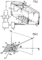
- the ultrasonic mechanical parts cleaning device shown in FIG. 1, object of the invention comprises a tank 1 intended to receive a cleaning agent in which a part P to be cleaned is immersed.
- the cleaning agents which can be used are those already mentioned above in the description.
- the tank 1 is provided with transmitting electro-acoustic transducers capable of generating ultrasonic mechanical power waves within the cleaning agent.
- the transmitter transducers referenced T i are shown arranged in a particular arrangement on a wall of the tank, the wall 10 constituting the bottom thereof.
- the power required by the ultrasonic waves to obtain a satisfactory cleaning effect depending on the cleaning agent chosen as mentioned above must be between 1 and 5 Watts / cm2 of the surface of the part to be cleaned.
- the device also comprises means 3 for generating electrical signals periodicals intended to supply the transmitting transducers and means 5 for regulating the power of the ultrasonic wave emitted by the transmitters and means 4 for regulating the frequency of the emission of the ultrasonic wave. All of the aforementioned means allow fine regulation of the ultrasonic power or the ultrasonic power density emitted or to which the part to be cleaned is actually subjected during treatment.
- Means 6 for focusing the beam resulting from the ultrasonic wave emitted by the electro-acoustic transducers are further provided in order to focus and / or deflect the resulting beam towards the part P to be cleaned. It will be understood that the focusing and / or deflection of the resulting beam ultimately allows the localization of the ultrasonic energy emitted in an area delimited substantially by a solid angle in a determined direction. The location of the emission energy consequently allows a reduction in the electrical energy necessary to supply the transducers for obtaining an energy density in the localized area of emission sufficient for obtaining 'A satisfactory cleaning compared to the known devices of the prior art. In FIG. 1, the drive power stages of the transducers are not shown. A particular configuration of the network of transmitter transducers 2 will now be described in connection with FIG. 2.
- the network 2 of transmitting transducers can be constituted by a set of transducers distributed in a plane according to a rectangular mesh network comprising M columns of transducers aligned parallel to a first reference direction Ox and N lines of transducers arranged parallel to a second direction Oy perpendicular to the first direction Ox.
- the network 2 thus comprises M x N transmitting transducers, the center of the network corresponding substantially to a transducer is denoted O and the order of a line is denoted m, m lying between 1 and M, the order of a column being denoted n, n being between 1 and N.
- the emitting transducers T i are spaced along the directions Ox and Oy, the distance between each consecutive transducer in these directions can be identical. This distance is noted d.
- the direction perpendicular to the plane Ox, Oy containing the transducers is denoted Oz. Any point F of the space exposed to radiation from the network will thus be identified in spherical coordinates by the parameters ⁇ 0 angle of , Oz and ⁇ 0 angle of Ox with the projection of on the plane Ox, Oy containing the network 2.
- the interference field of the set of sources at point F is given by the relation I below: in which A represents the emission amplitude of an emitting transducer, ⁇ the wavelength of ultrasonic emission in the propagation medium constituted by the cleaning agent.
- This new relation II then makes it possible to define the direction, defined by the guiding parameters ⁇ 0, ⁇ 0 in which the resulting radiated field is maximum, this direction being analyzed as the intersection of a first cone of axis Ox of half-angle at the top ⁇ and a second cone of axis Oy, with a half-angle at the top ⁇ , these cones being defined by the above-mentioned relation II.
- phase shifts ⁇ x and ⁇ y necessary to obtain a maximum field at a point F located in a direction of guiding parameters ⁇ 0, ⁇ 0 are given for the directions Ox and Oy of the network by the relationship III below:
- the sign - indicates that the maximum field direction is inclined towards the negative phases, that is to say the delays with respect to the phase of the center O of the network.
- the maximum resulting field value obtained is equal to M x N x A where M x N is the total number of sources or transmitters and A the amplitude radiated by a transmitter.
- M x N is the total number of sources or transmitters and A the amplitude radiated by a transmitter.
- the distance d separating the transmitters from the network can be chosen so as to eliminate the second order focusing which can be obtained.
- the distance d satisfies the relation IV: in which ⁇ m represents the maximum admissible value for the half-angles at the top of the cones defining the direction of the maximum field with respect to the axes Ox and Oy already mentioned.
- the device of the invention due to the focusing of the ultrasonic energy in a preferred direction, makes it possible to carry out a concentration of this ultrasonic energy in the localized area cited above.
- This focusing has the effect of causing in particular in the vicinity of the part to be cleaned a series of overpressures and depressions in the propagation medium constituted by the cleaning agent, which have the effect, in connection with this cleaning agent, of pickling of the workpiece surface.
- the stripping phenomenon is in fact obtained by a phenomenon analogous to a cavitation phenomenon due to the generated overpressures and depressions, which causing turbulence around the resulting beam in the vicinity of the impact on the part, causes the latter to be cleaned.
- the propagation of ultrasound in the propagation fluid or cleaning agent causes the formation of bubbles which implode under the action of ultrasonic acoustic pressure.
- This implosion generates a very large shock wave.
- This phenomenon known as cavitation originates in certain zones, functions of parameters such as, frequency of emission, power, temperature.
- the emission frequency of the ultrasonic waves is taken to be equal to or greater than 20 kHz.
- FIGS. 3a and 3b A detailed description of an advantageous embodiment of the structure of the network 2 will now be given in conjunction with FIGS. 3a and 3b.
- the transducers T i are fixed to the wall 10 of the tank projecting relative to the latter.
- the transducers constituted essentially by a sandwich of piezoelectric ceramic and vibrating metallic masses were fixed on a diaphragm integral with the wall of the tank at one end of the metallic masses.
- the mechanical vibration of the vibrating masses is maximum at the free ends of the vibrating masses and minimum or zero in the center, that is to say at the level of the junction of the two piezoelectric ceramic pellets.
- transducers are perfectly known from the state of the art.
- the necessary connection of the free end of a vibrating mass to the diaphragm is normally carried out by gluing, soldering or welding.
- This technique however has the disadvantage that the connection of the transducer to the diaphragm is located at the place of greatest amplitude of vibration. This necessarily results in fatigue of the diaphragm transducer mechanical connection and, in the long run, faulty operation of the assembly.
- the powers necessary to obtain the cleaning effect in the absence of focusing of the resulting beam most often require the presence of several transducers on the same diaphragm.
- This latter feature has the drawback of an inevitable mechanical coupling between transducers located on the same diaphragm, any phase shift applied to one of the transducers being necessarily coupled to neighboring transducers. There can therefore be no independent emission or ultimately separate control of the transducers.
- the particular embodiment shown by means of Figures 3a and 3b overcomes the aforementioned drawbacks.
- the transducers T i are fixed to the wall 10 of the tank in the vicinity of their middle part substantially. It will thus be understood that the transducers can be fixed to the wall by soldering at the end not free of a vibrating mass, that is to say the end of the vibrating mass directly in contact with one of the piezoelectric pellets constituting the transducer.
- This embodiment of course allows a better lifetime of the transducer connection wall of the tank since the connecting element used, such as a solder or a weld or the like, is subjected to a vibration of amplitude substantially zero or very weak.
- the transducers T i are constituted by the piezoelectric ceramics 1O3, 1O4, the vibrating masses 1O1, 1O2, the vibrating mass 1O1 being fixed to the wall 1O in the vicinity of the piezo ceramic pellet. electric 1O3.
- the excitation of each transducer is obtained from an excitation wire 1O6 connected to an electrode 1O5 ensuring the junction of the piezoelectric pads 1O3, 1O4.
- the transducers can be fixed to a removable part of the tank 1, the removable part itself being able to constitute a wall of a sealed housing containing the electronic control and supply circuits of the emitting transducers.
- the arrangement of transmitter transducers is constituted by a plate 1OO of a single piece on which are distributed pads 1011 or mechanical masses in a network configuration.
- Each pad 1011 is in fact intended to constitute the vibrating mass located in the tank of each transducer.
- the active part of each transducer is attached opposite each stud on the opposite face of the plate 1OO.
- the same references 1O3, 1O4, 1O5, 1O6, represent the same elements as in FIG. 3a.
- a seal 110 can also be provided to ensure repetitive assembly / disassembly of the removable plate for cleaning purposes for example.
- FIG. 3b also presents certain advantages from the point of view of ease of implementation, the plate 1OO, in one piece, which can be machined under conditions of mechanical tolerance that are entirely satisfactory. , which allow good focusing accuracy of the resulting beam.
- the means for regulating the power and the frequency of emission of the ultrasonic wave comprise a receiver transducer 7 arranged in the tank and preferably placed in the vicinity of the location intended for part P to be cleaned.
- the receiver transducer 7 can be removably mounted with respect to the part P in a direction of translation denoted for example X parallel to the network 2 and in the vertical direction denoted Z.
- the receiver transducer 7 thus allows a reading of the ultrasonic power received by the part to be cleaned P in different localized areas of the surface thereof.
- the transducer 7 can be mounted on a mobile carriage, which will not be described since it is perfectly known from the state of the art.
- the transducer 7 delivers an electrical signal representative of the frequency and of the transmission power of the ultrasonic wave emitted by the transmitting transducers to a first detection circuit 4 capable of generating a signal proportional to the frequency of the electrical signal delivered by the receiving transducer 7. Since the signal delivered by the receiving transducer 7 is substantially sinusoidal, the detection circuit 4 can be constituted by a zero crossing detection circuit normally available on the market or by a frequency discriminator. The signal delivered by the receiver transducer 7 is also also delivered to a second detection circuit 5 capable of generating a signal proportional to the level of the electrical signal delivered by the receiver transducer 7.
- the second detection circuit 5 can be constituted by a simple double-wave rectification circuit then delivering a signal representative of the power of the signal generated by the receiver transducer 7 and therefore of the power of the ultrasonic wave emitted by the transmitter transducers 2 or of the power ultrasonic received by the localized area of the part subjected to the impact of the beam.
- the signals delivered by the detectors 4 and 5 then make it possible to control the means 3 for generating periodic electrical signals intended to supply the transducers.
- the control in transmission frequency of the ultrasonic wave and in transmission power can thus be implemented with respect to respective set values of frequency and / or transmission power.
- the generator means 3 preferably deliver to the transmitter transducers 2 electrical signals formed by rectangular pulses of adjustable repetition frequency.
- the frequency of recurrence of the signals is controlled from the signal delivered by the detection circuit 4.
- the generator means 3 deliver to the transmitting transducers electrical signals with adjustable duty cycle thereby allowing power regulation. of the ultrasonic wave emitted by the transmitting transducers.
- the control of the value of the duty cycle of the signals delivered by the generator means 3 is carried out on the basis of the signal delivered by the detector 5.
- the supply of the transmitting transducers by means of rectangular pulses therefore allows precise control of the emission parameters which are the frequency and the power of emission.
- This type of supply to the transmitting transducers also allows an improvement in the efficiency of the electrical circuits, as well as a reduction in the width to 6 dB of the beams emitted by the transducers.
- the generator means 3 can be constituted by a pulse generator with repetition frequency and adjustable duty cycle on the market and for example by an integrated circuit MC 342O distributed by the company MOTOROLA.
- the generator 3 controlled by the detectors 4 and 5 delivers the rectangular pulses to focusing means 6 of the beam resulting from the emitted ultrasonic wave constituted by programmable delay means.
- the programmable delay means 6 comprise a control input denoted C and a plurality of outputs denoted S each connected to a transducer T i of the network 2.
- the connection between an output S of the focusing means 6 and a transducer T i has been represented by means of power circuits capable of generating pulses capable of exciting the transducers T i , of course, keeping imperatively the phase relationships or delays between pulses in accordance with the phase laws as given previously in by means of relation III.
- FIG. 1 the generator 3 controlled by the detectors 4 and 5 delivers the rectangular pulses to focusing means 6 of the beam resulting from the emitted ultrasonic wave constituted by programmable delay means.
- the programmable delay means 6 comprise a control input denoted C and a plurality of outputs denoted S each connected to a
- power circuits have been shown as consisting of two circuits connected in parallel 41, 43, 46; 42, 44, 47 allowing the application of a power voltage pulse to an isolation transformer 48.
- the circuits 41, 42 can be constituted by opto-electronic coupling circuits forming galvanic isolation of all the control circuits of the power control part. These circuits are normally available in trade.
- the circuits 43 and 44 are logic command and control circuits, allowing the corresponding control of power switching transistors constituting the circuits 46 and 47.
- the switching transistors constituting the aforementioned circuits 46 and 47 are connected in series with the primary winding of the isolation transformer 48 so as to apply to it a DC voltage of a power supply denoted + on the circuit 46.
- the logic control circuits 43 and 44 will not be subject to '' a detailed description because their function is limited to the restitution of the pulses transmitted by the opto-electronic coupling circuits 41 and 42 with possibly, if necessary, additional functions capable of ensuring the safety of the switching operations generated by the switching transistors of the circuits 46 and 47.
- the secondary winding of the isolation transformer 48 is connected to the transducers directors T i via a circuit 49 for compensating for example to obtain for each transducer calibrated pulses of the same level. It will of course be understood that each of the outputs S of the focusing means 6 is connected to the corresponding transmitter transducers T i by a power circuit identical to that shown in FIG. 4.
- the focusing means 6 will now be described in conjunction with FIG. 5.
- the focusing means 6 are constituted by delay circuits capable of each delivering the pulse or pulses delivered by the generating means 3 with a delay determined according to the address and the position of the corresponding transmitter transducer T i .
- the excitation delay of each transducer obtained by the corresponding delay of the pulses applied to the excitation electrode 10 6 of the transducers, allows the application of the phase shifts ⁇ x , ⁇ y to each transmitting transducer of the network 2 as a function of the address m, n thereof for obtaining a focusing of the beam in a given direction ⁇ 0, ⁇ 0 according to relation III already mentioned.
- the delay circuits or means as shown in FIG. 5, comprise a plurality of D type flip-flops connected in cascade.
- the flip-flops have been noted 1 to R.
- Each flip-flop receives a synchronization clock signal noted H and the output Q of a flip-flop of order smaller than R is connected to the input of the flip-flop next.
- the input of the first flip-flop receives the rectangular pulse signal delivered by the pulse generator 3.
- the output Q of any flip-flop of order k delivers a pulse delayed relative to the pulse delivered to the input of the first flip-flop of order 1 by the generator 3 delayed by kx ⁇ T .
- the output of each of the D type flip-flops is also connected to the power stage of the transmitter transducers by means of a channel selector circuit noted 61 in FIG. 5.
- the channel selector circuits 61 can be constituted by 8, 12, 16 bit programmable channel selector circuits, depending on the number of channels, normally available commercially.
- Each channel selector circuit61 is further connected to a control BUS 62 in fact constituting the control input denoted C shown previously in FIG. 4.
- the delay circuits or means as represented in FIG. 5 thus make it possible to apply a quantized phase shift value to a number of determined levels of elementary values at the pulses supplying each of the transducers as a function of a program capable of taking account of course of the direction in which it is necessary to focus the ultrasonic energy in the resulting beam but also of other parameters such as the shape and the dimensions of the part to be cleaned, the beam opening angle, the level of ultrasonic energy to be applied to the part as a function of the cleaning agent constituting the propagation medium, all of the aforementioned parameters being able to be organized in order to constitute any optimal sequence of cleaning of the part according to the treatment or treatments carried out or later applied.
Landscapes
- Engineering & Computer Science (AREA)
- Physics & Mathematics (AREA)
- Acoustics & Sound (AREA)
- Multimedia (AREA)
- Mechanical Engineering (AREA)
- Cleaning By Liquid Or Steam (AREA)
- Brushes (AREA)
Claims (12)
- Anlage zur Reinigung mechanischer Teile durch Ultraschall, mit einer Wanne (1), die zur Aufnahme eines Reinigungsmittels bestimmt ist, in das ein zu reinigendes Teil (P) eintauchbar ist, wobei die Wanne (1) mit elektroakustischen Sendewandlern (2) versehen ist, die dazu geeignet sind, mechanische Ultraschall-Wellenenergie innerhalb des Reinigungsmittels zu erzeugen, wobei die genannte Anlage Generatormittel (3) für periodische elektrische Signale, die für die Versorgung der genannten Wandler bestimmt sind, und Regelmittel (4) für die Aussendefrequenz der Ultraschallwelle aufweist, dadurch gekennzeichnet, daß die genannten Generatormittel (3) den Wandlern elektrische Signale liefern, die durch Rechteckimpulse einstellbarer Wiederholfrequenz gebildet sind, daß die genannte Anlage außerdem einerseits Regelmittel (5) für die Stärke der Ultraschallwelle und andererseits Fokussiermittel (6) für ein erzeugbares Bündel aufweist, die die Fokussierung und/oder Ablenkung des Bündels in Richtung auf das zu reinigende Teil ermöglichen, daß die genannten Fokussiermittel (6) für das erzeugbare Bündel der Ultraschallwelle durch programmierbare Verzögerungsmittel gebildet sind, die zwischen den Ausgang der genannten Generatormittel und jeden der Sendewandler geschaltet sind, und daß jedes der Verzögerungsmittel dazu geeignet ist, Impulse, die von den Generatormitteln (3) geliefert werden, mit einer Verzögerung abzugeben, gemäß der Adresse und der Position des entsprechenden Sendewandlers.
- Anlage nach Anspruch 1, dadurch gekennzeichnet, daß die genannten Generatormittel an die Wandler elektrische Signale liefern, deren Zyklusverhältnisse einstellbar sind, wodurch die Steuerung der Stärke der durch die Wandler ausgesandten Ultraschallwelle ermöglicht wird.
- Anlage nach einem der vorausgehenden Ansprüche, dadurch gekennzeichnet, daß die genannten elektroakustischen Sendewandler (Ti) an einer Wand der Wanne in vorbestimmter Anordnung vorgesehen sind, wobei die genannten Wandler bezüglich der Wand der Wanne vorspringend sind.
- Anlage nach Anspruch 3, dadurch gekennzeichnet, daß die genannten Wandler (Ti) an der Wand (10) der Wanne, deren mittlerem Teil in etwa benachbart, befestigt sind.
- Anlage nach Anspruch 4, dadurch gekennzeichnet, daß die genannten Wandler an einem unbeweglichen Teil der Wand der Wanne befestigt sind, wobei der genannte unbewegliche Teil selbst eine Wand eines dichten Gehäuses bilden kann, das die elektronischen Schalteinrichtungen für Steuerung und Versorung der Sendewandler einschließt.
- Anlage nach Anspruch 4 oder 5, dadurch gekennzeichnet, daß die Anordnung der Sendewandler mittels einer einstückigen Platte gebildet ist, an der Blöcke oder mechanische Massen in einem Raster verteilt angeordnet sind, wobei der aktive Teil jedes Wandlers jeweils einem Block gegenüberliegend auf der entgegengesetzten Seite der Platte angebracht ist.
- Anlage nach einem der vorausgehenden Ansprüche, dadurch gekennzeichnet, daß die Regelmittel für die Stärke und die Aussendefrequenz der Ultraschallwelle aufweisen:- einen Empfängerwandler (7), der in der Wanne angeordnet und vorzugsweise in der Nachbarschaft des für das zu reinigende Teil (P) bestimmten Ortes gelegen ist, wobei der genannte Wandler (7) ein elektrisches Signal liefert, das für die Frequenz und die Stärke der Aussendung der Ultraschallwelle der Sendewandler kennzeichnend ist,- eine erste Detektorschaltung (4), die dazu geeignet ist, ein Signal proportional der Frequenz des vom Empfängerwandler gelieferten elektrischen Signals zu erzeugen,- eine zweite Detektorschaltung (5), die dazu geeignet ist, ein Signal zu erzeugen, das proportional dem Pegel des durch den Empfängerwandler gelieferten elektrischen Signals und für die Stärke der Ultraschallwelle kennzeichnend ist, die durch die Wandler ausgesandt wird.
- Anlage nach einem der Ansprüche 1 bis 6, dadurch gekennzeichnet, daß die genannten Generatormittel (3) durch einen Impulsgenerator gebildet sind, dessen Wiederholfrequenz und Zyklusverhältnisse einstellbar sind.
- Anlage nach Anspruch 1, dadurch gekennzeichnet, daß die Verzögerungsmittel eine Mehrzahl von Schaltungen vom D-Typ in Kaskadenschaltung besitzen, wobei jede Schaltung ein synchronisierendes Taktsignal (H) erhält und der Ausgang (Q) bei jeder eine niedrigere Ordnung als R aufweisenden Schaltung mit dem Eingang der nächstfolgenden Schaltung verbunden ist, wobei der Eingang der ersten Schaltung das Signal in Rechteckimpulsen erhält, das vom Impulsgenerator geliefert wird, und der Ausgang jeder der Schaltungen mit der Leistungsstufe der Sendewandler mittels einer Wählschaltung für programmierbare Kanäle verbunden ist.
- Anlage nach Anspruch 9, dadurch gekennzeichnet, daß die genannten Wählschaltungen für programmierbare Kanäle mittels eines Mikrocomputers gesteuert sind, wobei der genannte Mikrocomputer mit den Kanalwählern verbunden ist, die Phasenschieber bilden, die mittels einer Steuerlogik programmierbar sind.
- Verfahren zum Reinigen von mechanischen Teilen durch Ultraschall, bestehend aus dem in Stellung bringen des genannten Teils (P) in einer Wanne (1), die ein Reinigungsmittel enthält und elektroakustische Sendewandler (2) aufweist, die zur Erzeugung mechanischer Ultraschallwellenenergie innerhalb des Reinigungsmittels in der Weise geeignet sind, daß in der Nachbarschaft des Teiles Turbulenzzonen und eine Kavitationserscheinung erzeugt wird, die eine Reinigung desselben hervorruft, wobei eine Filterung der in dem Reinigungsmittel in Suspension gehenden Partikel auf dem Niveau der Turbulenzzonen sichergestellt ist und die genannten Wandler durch Generatormittel (3) für periodische elektrische Signale versorgt werden, deren Sendefrequenz durch Regelmittel (4) geregelt wird, dadurch gekennzeichnet, daß die genannten Generatormittel (3) an die Wandler (2) elektrische Signale liefern, die durch Rechteckimpulse einstellbarer Wiederholfrequenz gebildet sind, und die Stärke der Ultraschallwelle durch Regelmittel (5) geregelt wird, was bezweckt, daß das resultierende Bündel der Ultraschallwelle, das von den genannten Wandlern ausgesandt wird, fokussiert und/oder auf das genannte Teil (P) abgelenkt wird, mit Hilfe von Fokussiermitteln (6), die durch programmierbare Verzögerungsmittel gebildet sind, die zwischen den Ausgang der genannten Generatormittel (3) und jeden der Sendewandler (2) geschaltet sind, wobei jedes der Verzögerungsmittel dazu vorgesehen ist, den durch die Generatormittel (3) gelieferten Impuls mit einer entsprechend der Adresse und der Lageanordnung des entsprechenden Sendewandlers bestimmten Verzögerung zuzuführen.
- Verfahren nach Anspruch 11, dadurch gekennzeichnet, daß es vom Mikrocomputer sequentiell durchgeführt wird, wobei die genannten Sequenzen in Abhängigkeit von der Topologie des zu reinigenden Teiles (P) eingerichtet werden.
Priority Applications (1)
| Application Number | Priority Date | Filing Date | Title |
|---|---|---|---|
| AT86400820T ATE68379T1 (de) | 1985-04-16 | 1986-04-16 | Ultraschallreinigungsanlage fuer mechanische teile. |
Applications Claiming Priority (2)
| Application Number | Priority Date | Filing Date | Title |
|---|---|---|---|
| FR8505710 | 1985-04-16 | ||
| FR8505710A FR2580198B1 (fr) | 1985-04-16 | 1985-04-16 | Dispositif de nettoyage de pieces mecaniques par ultrasons |
Publications (2)
| Publication Number | Publication Date |
|---|---|
| EP0205355A1 EP0205355A1 (de) | 1986-12-17 |
| EP0205355B1 true EP0205355B1 (de) | 1991-10-16 |
Family
ID=9318279
Family Applications (1)
| Application Number | Title | Priority Date | Filing Date |
|---|---|---|---|
| EP86400820A Expired - Lifetime EP0205355B1 (de) | 1985-04-16 | 1986-04-16 | Ultraschallreinigungsanlage für mechanische Teile |
Country Status (4)
| Country | Link |
|---|---|
| EP (1) | EP0205355B1 (de) |
| AT (1) | ATE68379T1 (de) |
| DE (1) | DE3681968D1 (de) |
| FR (1) | FR2580198B1 (de) |
Cited By (2)
| Publication number | Priority date | Publication date | Assignee | Title |
|---|---|---|---|---|
| DE112009002186B4 (de) * | 2008-09-09 | 2016-03-03 | Mitsubishi Electric Corp. | Ultraschallgenerator und Vorrichtung zu dessen Befestigung |
| CN111359977A (zh) * | 2018-09-09 | 2020-07-03 | 衢州市科诚技术开发有限公司 | 一种汽车零件处理用滤除杂质的清洗装置 |
Families Citing this family (15)
| Publication number | Priority date | Publication date | Assignee | Title |
|---|---|---|---|---|
| SE456971B (sv) * | 1987-03-18 | 1988-11-21 | Douglas H Mcqueen | Ultraljudsinstrument |
| GB8811259D0 (en) * | 1988-05-12 | 1988-06-15 | Ae Turbine Components | Decontamination method & apparatus |
| FR2653564B1 (fr) * | 1989-10-20 | 1992-01-24 | Thomson Csf | Procede de formation de voies pour sonar. |
| WO1996015863A1 (en) * | 1994-11-22 | 1996-05-30 | United Technologies Corporation | Cleaning method for turbine airfoils by ultrasonics |
| EP0774305A3 (de) * | 1995-11-16 | 1998-07-01 | Keith S. Campbell | Ultraschallreinigungsvorrichtung und Verfahren zur Reinigung von Kronleuchtern |
| FR2762240B1 (fr) * | 1997-04-18 | 1999-07-09 | George Lucien Michel | Procede et dispositif de nettoyage d'elements electroniques par moyennes ou hautes frequences |
| JP2007500941A (ja) | 2003-07-31 | 2007-01-18 | エフエスアイ インターナショナル インコーポレイテッド | 高度に均一な酸化物層、とりわけ超薄層の調節された成長 |
| TW200515475A (en) * | 2003-09-11 | 2005-05-01 | Fsi Int Inc | Acoustic diffusers for acoustic field uniformity |
| WO2010058293A2 (en) * | 2008-11-21 | 2010-05-27 | Insightec Ltd. | Method and apparatus for washing fabrics using focused ultrasound |
| CN102350418A (zh) * | 2011-06-24 | 2012-02-15 | 戚祖强 | 基于ZigBee无线控制的超声波水槽 |
| KR102631306B1 (ko) * | 2015-04-27 | 2024-01-30 | 삼성전자주식회사 | 국소 진동장 형성 장치 및 방법과, 가진기 배치 방법 |
| FI127711B (en) * | 2016-05-13 | 2018-12-31 | Altum Tech Oy | METHOD FOR CLEANING THE APPLIANCE |
| WO2020202200A1 (en) * | 2019-03-29 | 2020-10-08 | S Nikhil Das | Apparatus and method for reducing concentration polarization and membrane fouling on membrane surface in a filter unit |
| CN112044861A (zh) * | 2020-08-27 | 2020-12-08 | 湖州南浔吾心信息技术有限公司 | 一种利用超声波实现杀菌的键盘清理装置 |
| CN120001719A (zh) * | 2025-01-26 | 2025-05-16 | 哈尔滨工业大学(深圳)(哈尔滨工业大学深圳科技创新研究院) | 一种超声清洗系统 |
Family Cites Families (8)
| Publication number | Priority date | Publication date | Assignee | Title |
|---|---|---|---|---|
| FR764869A (fr) * | 1933-07-29 | 1934-05-29 | Dispositif pour la transformation de l'énergie acoustique en énergie électrique, et inversement | |
| FR876822A (fr) * | 1940-11-18 | 1942-11-18 | Atlas Werke Ag | Dispositif pour la production de champs sonores convergents |
| FR1142784A (fr) * | 1955-03-07 | 1957-09-23 | Bendix Aviat Corp | Agitateur de liquide perfectionné |
| FR1207076A (fr) * | 1957-07-10 | 1960-02-15 | Pfenningsberg Gmbh Maschfab | Procédé et appareil pour le lavage ultrasonore, notamment des matières solides |
| FR1459910A (fr) * | 1965-09-11 | 1966-06-17 | Ultrasonics Ltd | Dispositif de montage d'une sonde formant transducteur dans un récipient contenant un liquide de nettoyage |
| US4120699A (en) * | 1974-11-07 | 1978-10-17 | Alvin B. Kennedy, Jr. | Method for acoustical cleaning |
| JPS5540829B2 (de) * | 1975-01-13 | 1980-10-20 | ||
| IT1141417B (it) * | 1980-04-11 | 1986-10-01 | Dario Felisari | Convertitore elettromeccanico monoblocco per l'emissione di onde acustiche ultrasonore nei liquidi tramite l'eccitazione in risonanza meccanica di elementi della stessa parete di contenimento isolati dalla interazione del contorno da opportuni canali di smorzamento |
-
1985
- 1985-04-16 FR FR8505710A patent/FR2580198B1/fr not_active Expired
-
1986
- 1986-04-16 DE DE8686400820T patent/DE3681968D1/de not_active Expired - Fee Related
- 1986-04-16 EP EP86400820A patent/EP0205355B1/de not_active Expired - Lifetime
- 1986-04-16 AT AT86400820T patent/ATE68379T1/de not_active IP Right Cessation
Cited By (3)
| Publication number | Priority date | Publication date | Assignee | Title |
|---|---|---|---|---|
| DE112009002186B4 (de) * | 2008-09-09 | 2016-03-03 | Mitsubishi Electric Corp. | Ultraschallgenerator und Vorrichtung zu dessen Befestigung |
| CN111359977A (zh) * | 2018-09-09 | 2020-07-03 | 衢州市科诚技术开发有限公司 | 一种汽车零件处理用滤除杂质的清洗装置 |
| CN111359977B (zh) * | 2018-09-09 | 2021-09-21 | 陈丹青 | 一种汽车零件处理用滤除杂质的清洗装置 |
Also Published As
| Publication number | Publication date |
|---|---|
| DE3681968D1 (de) | 1991-11-21 |
| FR2580198B1 (fr) | 1988-09-09 |
| FR2580198A1 (fr) | 1986-10-17 |
| ATE68379T1 (de) | 1991-11-15 |
| EP0205355A1 (de) | 1986-12-17 |
Similar Documents
| Publication | Publication Date | Title |
|---|---|---|
| EP0205355B1 (de) | Ultraschallreinigungsanlage für mechanische Teile | |
| US4979994A (en) | Method and apparatus for cleaning by ultrasonic wave energy | |
| EP0612570B1 (de) | Verfahren zum oszillieren eines Ultraschallvibrators für Ultraschallreinigung | |
| EP0289382B1 (de) | Generator für elastische Impulse von vorgegebener gewünschter Form und seine Anwendung in medizinischer Behandlung oder Diagnose | |
| EP0176155A1 (de) | Vorrichtung mit Winkelfokussierung zur echographischen Untersuchung von Medien mittels Ultraschall | |
| JP4984519B2 (ja) | 超音波による金属材料の断面検査方法及び装置 | |
| EP0383650A1 (de) | Verfahren und Vorrichtung zum Orten und Fokussieren von Wellen | |
| US9307325B2 (en) | Transducer arrangement | |
| EP0543445B1 (de) | Untersuchungsgerät von Medien mittels Ultraschall-Echographie | |
| WO1996022527A1 (en) | Bore probe for tube inspection with guided waves and method therefor | |
| FR2910826A1 (fr) | Dispositif pour la production de vibrations ultrasoniques | |
| CN108602093B (zh) | 用于激励压电换能器的方法和声源装置 | |
| CA2657708C (fr) | Procede et dispositif de transmission d'ondes | |
| US3836948A (en) | Echo sounding technique | |
| FR3102377B1 (fr) | Equipement et procédé de dépôt par projection de particules par ondes de choc laser | |
| US6489707B1 (en) | Method and apparatus for generating acoustic energy | |
| WO1992011546A1 (en) | Transmission-reception device of acoustic signals for marine environment exploration | |
| EP0115720A1 (de) | Elektronenkanone für Linearbeschleuniger und Beschleunigungsstruktur mit derartiger Kanone | |
| FR2473362A1 (fr) | Procede et appareil d'usinage electrique avec liquide d'usinage interpose entre l'outil et la piece a usiner | |
| JPH0211867B2 (de) | ||
| FR2762240A1 (fr) | Procede et dispositif de nettoyage d'elements electroniques par moyennes ou hautes frequences | |
| AU642418B2 (en) | A method and a system for combating marine fouling | |
| FR2675262A1 (fr) | Methode de selection de traducteurs ultrasonores et traducteurs selectionnes selon cette methode. | |
| EP0040566B1 (de) | Echographisches Gerät mit dynamischer Fokussierung und Sektorabtastung | |
| WO1996037314A1 (fr) | Procede et dispositif de lavage et de nettoyage |
Legal Events
| Date | Code | Title | Description |
|---|---|---|---|
| PUAI | Public reference made under article 153(3) epc to a published international application that has entered the european phase |
Free format text: ORIGINAL CODE: 0009012 |
|
| AK | Designated contracting states |
Kind code of ref document: A1 Designated state(s): AT BE CH DE FR GB IT LI LU NL SE |
|
| 17P | Request for examination filed |
Effective date: 19870518 |
|
| 17Q | First examination report despatched |
Effective date: 19880728 |
|
| GRAA | (expected) grant |
Free format text: ORIGINAL CODE: 0009210 |
|
| RAP3 | Party data changed (applicant data changed or rights of an application transferred) |
Owner name: OMEGA TECHNOLOGIES |
|
| AK | Designated contracting states |
Kind code of ref document: B1 Designated state(s): AT BE CH DE FR GB IT LI LU NL SE |
|
| PG25 | Lapsed in a contracting state [announced via postgrant information from national office to epo] |
Ref country code: SE Effective date: 19911016 Ref country code: NL Effective date: 19911016 Ref country code: AT Effective date: 19911016 |
|
| REF | Corresponds to: |
Ref document number: 68379 Country of ref document: AT Date of ref document: 19911115 Kind code of ref document: T |
|
| REF | Corresponds to: |
Ref document number: 3681968 Country of ref document: DE Date of ref document: 19911121 |
|
| ITF | It: translation for a ep patent filed | ||
| GBT | Gb: translation of ep patent filed (gb section 77(6)(a)/1977) | ||
| NLV1 | Nl: lapsed or annulled due to failure to fulfill the requirements of art. 29p and 29m of the patents act | ||
| PGFP | Annual fee paid to national office [announced via postgrant information from national office to epo] |
Ref country code: GB Payment date: 19920416 Year of fee payment: 7 |
|
| PG25 | Lapsed in a contracting state [announced via postgrant information from national office to epo] |
Ref country code: LU Free format text: LAPSE BECAUSE OF NON-PAYMENT OF DUE FEES Effective date: 19920430 |
|
| PLBE | No opposition filed within time limit |
Free format text: ORIGINAL CODE: 0009261 |
|
| STAA | Information on the status of an ep patent application or granted ep patent |
Free format text: STATUS: NO OPPOSITION FILED WITHIN TIME LIMIT |
|
| 26N | No opposition filed | ||
| PGFP | Annual fee paid to national office [announced via postgrant information from national office to epo] |
Ref country code: CH Payment date: 19921027 Year of fee payment: 7 |
|
| PGFP | Annual fee paid to national office [announced via postgrant information from national office to epo] |
Ref country code: DE Payment date: 19921028 Year of fee payment: 7 |
|
| PGFP | Annual fee paid to national office [announced via postgrant information from national office to epo] |
Ref country code: BE Payment date: 19921116 Year of fee payment: 7 |
|
| PG25 | Lapsed in a contracting state [announced via postgrant information from national office to epo] |
Ref country code: GB Effective date: 19930416 |
|
| PG25 | Lapsed in a contracting state [announced via postgrant information from national office to epo] |
Ref country code: LI Effective date: 19930430 Ref country code: CH Effective date: 19930430 Ref country code: BE Effective date: 19930430 |
|
| BERE | Be: lapsed |
Owner name: OMEGA TECHNOLOGIES Effective date: 19930430 |
|
| GBPC | Gb: european patent ceased through non-payment of renewal fee |
Effective date: 19930416 |
|
| REG | Reference to a national code |
Ref country code: CH Ref legal event code: PL |
|
| PG25 | Lapsed in a contracting state [announced via postgrant information from national office to epo] |
Ref country code: DE Effective date: 19940101 |
|
| PGFP | Annual fee paid to national office [announced via postgrant information from national office to epo] |
Ref country code: FR Payment date: 19980527 Year of fee payment: 13 |
|
| PG25 | Lapsed in a contracting state [announced via postgrant information from national office to epo] |
Ref country code: FR Free format text: LAPSE BECAUSE OF NON-PAYMENT OF DUE FEES Effective date: 19991231 |
|
| REG | Reference to a national code |
Ref country code: FR Ref legal event code: ST |
|
| PG25 | Lapsed in a contracting state [announced via postgrant information from national office to epo] |
Ref country code: IT Free format text: LAPSE BECAUSE OF NON-PAYMENT OF DUE FEES;WARNING: LAPSES OF ITALIAN PATENTS WITH EFFECTIVE DATE BEFORE 2007 MAY HAVE OCCURRED AT ANY TIME BEFORE 2007. THE CORRECT EFFECTIVE DATE MAY BE DIFFERENT FROM THE ONE RECORDED. Effective date: 20050416 |