EP0206182A1 - Fluidfilter mit gefaltetem Filtermedium - Google Patents
Fluidfilter mit gefaltetem Filtermedium Download PDFInfo
- Publication number
- EP0206182A1 EP0206182A1 EP86108140A EP86108140A EP0206182A1 EP 0206182 A1 EP0206182 A1 EP 0206182A1 EP 86108140 A EP86108140 A EP 86108140A EP 86108140 A EP86108140 A EP 86108140A EP 0206182 A1 EP0206182 A1 EP 0206182A1
- Authority
- EP
- European Patent Office
- Prior art keywords
- filter
- section
- pleat
- fluid
- sealing member
- Prior art date
- Legal status (The legal status is an assumption and is not a legal conclusion. Google has not performed a legal analysis and makes no representation as to the accuracy of the status listed.)
- Granted
Links
- 239000012530 fluid Substances 0.000 title claims abstract description 103
- 238000007789 sealing Methods 0.000 claims abstract description 85
- 239000000463 material Substances 0.000 claims description 23
- 229920002635 polyurethane Polymers 0.000 claims description 10
- 239000004814 polyurethane Substances 0.000 claims description 10
- 229920000915 polyvinyl chloride Polymers 0.000 claims description 3
- 239000004800 polyvinyl chloride Substances 0.000 claims description 3
- 230000002093 peripheral effect Effects 0.000 abstract description 26
- 239000003570 air Substances 0.000 description 61
- 238000001914 filtration Methods 0.000 description 12
- 239000000853 adhesive Substances 0.000 description 10
- 230000001070 adhesive effect Effects 0.000 description 10
- 239000000428 dust Substances 0.000 description 6
- 238000002485 combustion reaction Methods 0.000 description 4
- 239000010687 lubricating oil Substances 0.000 description 4
- 230000000994 depressogenic effect Effects 0.000 description 3
- 230000009969 flowable effect Effects 0.000 description 3
- 238000000034 method Methods 0.000 description 3
- 238000000465 moulding Methods 0.000 description 3
- 229920003023 plastic Polymers 0.000 description 3
- 239000004033 plastic Substances 0.000 description 3
- 238000011144 upstream manufacturing Methods 0.000 description 3
- 230000009471 action Effects 0.000 description 2
- 239000000446 fuel Substances 0.000 description 2
- 239000012535 impurity Substances 0.000 description 2
- 239000004745 nonwoven fabric Substances 0.000 description 2
- 238000012856 packing Methods 0.000 description 2
- 230000008569 process Effects 0.000 description 2
- 230000000717 retained effect Effects 0.000 description 2
- 230000015572 biosynthetic process Effects 0.000 description 1
- 230000008859 change Effects 0.000 description 1
- 238000010276 construction Methods 0.000 description 1
- 230000007423 decrease Effects 0.000 description 1
- 230000003247 decreasing effect Effects 0.000 description 1
- 238000009826 distribution Methods 0.000 description 1
- 230000000694 effects Effects 0.000 description 1
- 230000006872 improvement Effects 0.000 description 1
- 238000004519 manufacturing process Methods 0.000 description 1
- 239000002184 metal Substances 0.000 description 1
- 229920005749 polyurethane resin Polymers 0.000 description 1
- 239000000843 powder Substances 0.000 description 1
- 238000003825 pressing Methods 0.000 description 1
- 238000004904 shortening Methods 0.000 description 1
- 125000006850 spacer group Chemical group 0.000 description 1
Images


Classifications
-
- B—PERFORMING OPERATIONS; TRANSPORTING
- B01—PHYSICAL OR CHEMICAL PROCESSES OR APPARATUS IN GENERAL
- B01D—SEPARATION
- B01D46/00—Filters or filtering processes specially modified for separating dispersed particles from gases or vapours
- B01D46/52—Particle separators, e.g. dust precipitators, using filters embodying folded corrugated or wound sheet material
- B01D46/521—Particle separators, e.g. dust precipitators, using filters embodying folded corrugated or wound sheet material using folded, pleated material
-
- B—PERFORMING OPERATIONS; TRANSPORTING
- B01—PHYSICAL OR CHEMICAL PROCESSES OR APPARATUS IN GENERAL
- B01D—SEPARATION
- B01D29/00—Filters with filtering elements stationary during filtration, e.g. pressure or suction filters, not covered by groups B01D24/00 - B01D27/00; Filtering elements therefor
- B01D29/01—Filters with filtering elements stationary during filtration, e.g. pressure or suction filters, not covered by groups B01D24/00 - B01D27/00; Filtering elements therefor with flat filtering elements
- B01D29/012—Making filtering elements
-
- B—PERFORMING OPERATIONS; TRANSPORTING
- B01—PHYSICAL OR CHEMICAL PROCESSES OR APPARATUS IN GENERAL
- B01D—SEPARATION
- B01D29/00—Filters with filtering elements stationary during filtration, e.g. pressure or suction filters, not covered by groups B01D24/00 - B01D27/00; Filtering elements therefor
- B01D29/01—Filters with filtering elements stationary during filtration, e.g. pressure or suction filters, not covered by groups B01D24/00 - B01D27/00; Filtering elements therefor with flat filtering elements
- B01D29/016—Filters with filtering elements stationary during filtration, e.g. pressure or suction filters, not covered by groups B01D24/00 - B01D27/00; Filtering elements therefor with flat filtering elements with corrugated, folded or wound filtering elements
-
- B—PERFORMING OPERATIONS; TRANSPORTING
- B01—PHYSICAL OR CHEMICAL PROCESSES OR APPARATUS IN GENERAL
- B01D—SEPARATION
- B01D29/00—Filters with filtering elements stationary during filtration, e.g. pressure or suction filters, not covered by groups B01D24/00 - B01D27/00; Filtering elements therefor
- B01D29/01—Filters with filtering elements stationary during filtration, e.g. pressure or suction filters, not covered by groups B01D24/00 - B01D27/00; Filtering elements therefor with flat filtering elements
- B01D29/018—Filters with filtering elements stationary during filtration, e.g. pressure or suction filters, not covered by groups B01D24/00 - B01D27/00; Filtering elements therefor with flat filtering elements ring shaped
-
- B—PERFORMING OPERATIONS; TRANSPORTING
- B01—PHYSICAL OR CHEMICAL PROCESSES OR APPARATUS IN GENERAL
- B01D—SEPARATION
- B01D29/00—Filters with filtering elements stationary during filtration, e.g. pressure or suction filters, not covered by groups B01D24/00 - B01D27/00; Filtering elements therefor
- B01D29/11—Filters with filtering elements stationary during filtration, e.g. pressure or suction filters, not covered by groups B01D24/00 - B01D27/00; Filtering elements therefor with bag, cage, hose, tube, sleeve or like filtering elements
- B01D29/111—Making filtering elements
-
- B—PERFORMING OPERATIONS; TRANSPORTING
- B01—PHYSICAL OR CHEMICAL PROCESSES OR APPARATUS IN GENERAL
- B01D—SEPARATION
- B01D29/00—Filters with filtering elements stationary during filtration, e.g. pressure or suction filters, not covered by groups B01D24/00 - B01D27/00; Filtering elements therefor
- B01D29/11—Filters with filtering elements stationary during filtration, e.g. pressure or suction filters, not covered by groups B01D24/00 - B01D27/00; Filtering elements therefor with bag, cage, hose, tube, sleeve or like filtering elements
- B01D29/13—Supported filter elements
- B01D29/15—Supported filter elements arranged for inward flow filtration
- B01D29/21—Supported filter elements arranged for inward flow filtration with corrugated, folded or wound sheets
-
- B—PERFORMING OPERATIONS; TRANSPORTING
- B01—PHYSICAL OR CHEMICAL PROCESSES OR APPARATUS IN GENERAL
- B01D—SEPARATION
- B01D46/00—Filters or filtering processes specially modified for separating dispersed particles from gases or vapours
- B01D46/0002—Casings; Housings; Frame constructions
- B01D46/0005—Mounting of filtering elements within casings, housings or frames
-
- B—PERFORMING OPERATIONS; TRANSPORTING
- B01—PHYSICAL OR CHEMICAL PROCESSES OR APPARATUS IN GENERAL
- B01D—SEPARATION
- B01D46/00—Filters or filtering processes specially modified for separating dispersed particles from gases or vapours
- B01D46/10—Particle separators, e.g. dust precipitators, using filter plates, sheets or pads having plane surfaces
-
- B—PERFORMING OPERATIONS; TRANSPORTING
- B01—PHYSICAL OR CHEMICAL PROCESSES OR APPARATUS IN GENERAL
- B01D—SEPARATION
- B01D46/00—Filters or filtering processes specially modified for separating dispersed particles from gases or vapours
- B01D46/24—Particle separators, e.g. dust precipitators, using rigid hollow filter bodies
- B01D46/2403—Particle separators, e.g. dust precipitators, using rigid hollow filter bodies characterised by the physical shape or structure of the filtering element
- B01D46/2411—Filter cartridges
-
- B—PERFORMING OPERATIONS; TRANSPORTING
- B01—PHYSICAL OR CHEMICAL PROCESSES OR APPARATUS IN GENERAL
- B01D—SEPARATION
- B01D2201/00—Details relating to filtering apparatus
- B01D2201/02—Filtering elements having a conical form
-
- B—PERFORMING OPERATIONS; TRANSPORTING
- B01—PHYSICAL OR CHEMICAL PROCESSES OR APPARATUS IN GENERAL
- B01D—SEPARATION
- B01D2201/00—Details relating to filtering apparatus
- B01D2201/12—Pleated filters
-
- B—PERFORMING OPERATIONS; TRANSPORTING
- B01—PHYSICAL OR CHEMICAL PROCESSES OR APPARATUS IN GENERAL
- B01D—SEPARATION
- B01D2201/00—Details relating to filtering apparatus
- B01D2201/34—Seals or gaskets for filtering elements
-
- B—PERFORMING OPERATIONS; TRANSPORTING
- B01—PHYSICAL OR CHEMICAL PROCESSES OR APPARATUS IN GENERAL
- B01D—SEPARATION
- B01D2265/00—Casings, housings or mounting for filters specially adapted for separating dispersed particles from gases or vapours
- B01D2265/06—Details of supporting structures for filtering material, e.g. cores
-
- B—PERFORMING OPERATIONS; TRANSPORTING
- B01—PHYSICAL OR CHEMICAL PROCESSES OR APPARATUS IN GENERAL
- B01D—SEPARATION
- B01D2279/00—Filters adapted for separating dispersed particles from gases or vapours specially modified for specific uses
- B01D2279/60—Filters adapted for separating dispersed particles from gases or vapours specially modified for specific uses for the intake of internal combustion engines or turbines
Definitions
- the present invention relates generally to fluid filters for filtering fluids such as air, fuel, lubricating oil and hydraulic fluid used in internal combustion engines to remove impurities such as dust and metal powders therefrom, and more particularly to an improvement in an pleated filter medium of such fluid filters thereby to attain a higher filtering ability and a longer filter life.
- filter element usually consists of a pleated filter medium formed of a sheet-type filter material such as filter paper or nonwoven fabric.
- the pleated filter medium is generally annular and has a plurality of longitudinally extending pleats.
- a pair of end plates are sealingly attached to the opposite ends of the annular filter medium by means of adhesive, securely disposing an inner perforated cylinder along the inner periphery of the annular filter medium.
- a pair of fluid sealing members are securely attached to the end plates, respectively, thus constituting the filter element.
- fluid such as air or lubricating oil to be filtered flows perpendicularly to the filter medium, i.e., the fluid is introduced through the outer peripheral face of the filter medium and gets out through the inner peripheral face of the filter medium in which dust and the like are removed and retained on the surface of the filter medium.
- the filtration rate at the part near the inlet becomes higher than an appropriate value while the fluid is difficult to flow at the part remote from the inlet.
- the pitch of the pleats is smaller at the filter medium inner periphery than at the outer periphery, the flow resistance and the life unavoidably depend on the pleat pitch of the filter medium inner periphery. Accordingly, if the number of the pleats is increased and the width of each pleat is enlarged for the purpose of lowering the flow resistance and prolong the life, effects thereon are hardly expected.
- a fluid filter according to the present invention consists of a filter element including a pleated filter medium having a plurality of pleats such as adjacent first and second pleats.
- Each pleat includes first and second sides which are integrally connected through an upper main score line with each other to form an upwardly-pointing pleat.
- the second side of the first pleat and the first side of the second pleat is integrally connected through a lower main score line with each other to form a downwardly-pointing pleat.
- Each pleat side has oppositely located first and second end sections which have first and second edges, respectively, which extend substantially perpendicular to each score line.
- the first end sections of the first pleat first and second sides are approached and bonded to each other thereby to form a first bonded section.
- the second end section of the first pleat second side and second end section of the second pleat first side are approached and bonded to each other to form a second bonded section.
- the flow path of a fluid to be filtered is formed nearly along the length of each pleat in which filtration is accomplished in a process of the fluid flowing along the pleat length so that impurities are uniformly retained throughout whole the filter medium. Accordingly, the fluid to be filtered is uniformly distributed throughout whole the surface of the filter medium, thereby uniformalizing flow of the fluid flowing through the filter medium and fitration rate.
- the filter medium of the present invention effectively improves filtration accuracy and prolongs the life of the filter element.
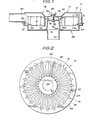
- a first embodiment of a fluid filter in accordance with the present invention is directed to an air filter 10 for an automotive internal combustion engine.
- the air filter 10 comprises a casing 12 within which a filter element 14 is securely disposed to remove dust contained in air to be supplied to the engine.
- the filter element 14 consists of a pleated filter medium 16 formed of a sheet-type filter material such as a filter paper or a nonwoven fabric.
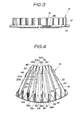
- the filter medium 16 is formed annular in this embodiment.
- the filter medium 16 includes a plurality of pleats 18 which extend radially between the inner and outer peripheries of the filter medium 16.
- Each pleat 18A, 18B includes first and second sides 20a, 20b which are integrally connected or contiguous through a upper or first main score line 22 thereby to form an upwardly-pointing pleat corresponding to that 8A. Additionally, the second side 20a of the first pleat 18A is integrally connected or contiguous through a lower or second main score line 24 with the first side 20a of the second pleat 18B thereby to form a downwardly-pointing pleat (not identified).
- Each pleat side 20a, 20b has outer and inner (first and second) end sections 24a, 24b which contain outer and inner first and second edges 26a, 26b, respectively, as best seen from Fig. 1. It will be understood that each edge 26a, 26b is perpendicular to the upper main score line 22.
- each pleat 18 (18A, 18B) are approached and bonded with each other by means of an adhesive, thus forming an outer or first bonded section B 1 0
- the inner end section 24b of the second side 20b of the first pleat 18A is approached and bonded to the inner end section 24b of the first side 20a of the second pleat 18B by means of an adhesive, thus forming an inner or second bonded section B 2 .
- the outer end section 24a (containing the outer edge 26a) of the pleat side 20a, 20b extends from the upper main score line 22 and has a length slightly smaller than the width W of the pleat side.
- the inner end section 24b containing the inner edge 26b of the pleat side 20a, 20b extends from the lower main score line 24 and has
- an outer or first inclined wall 28 of the shape of an isosceles triangle is formed between the first and second pleats 18A, 18B on the outer peripheral side.
- the outer incliend wall 28 has an edge 30 contiguous to the outer edges 26a of the pleat first and second sides 20a, 20b.
- the outer inclined wall 28 is integrally connected or contiguous through a first oblique score line 32a with the second side of the first pleat 18A and through a second oblique score line 32b with the first side 20a of the second pleat 18B.
- the first oblique score line 32a connects an end point 34 (on the outer peripheral side) of the lower main score line 24 and a point 36 lying at the border of the outer edge 26a of the second side 20b of the first pleat 18A and the edge 30 of the outer inclined wall 28.
- the second oblique score line 32b connects the end point 34 of the lower main score line 24 and a point 38 lying at the border of the outer edge 26a of the first side 20a of the second pleat 18B and the edge 30 of the first inclined wall 28.
- an inner or second incliend wall 40 of the shape of an isosceles triangle is formed contiguous to the upper main score line 22 and formed between the first and second sides 20a, 20b of each pleat 18 (18A, 18B) on the inner peripheral side.
- the inner inclined wall 40 has an edge 42 contiguous to the outer inner edges 26b of the first and second sides 20a, 20b of each pleat 18 (18A, 18B).
- the inner inclined wall 40 is integrally connected or contiguous through a third oblique score line 44a with the first side 20a of the pleat and through a fourth oblique score line 44b with the second side 20b of the pleat.
- the third oblique score line 44a connects an end point 46 (on the inner peripheral side) of the upper main score line 22 and a point 48 lying at the border between the inner edge 26b of the first side 20a of the pleat and the edge 42 of the inner inclined wall 40.
- the fourth oblique score line 44b connects the end point 46 of the upper main score line 22 and a point 50 lying at the border between the edge 42 of the second inclined wall 40 and the edge 26b of the second side 20b of the pleat.
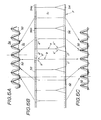
- a filter material F such as a filter paper of the band type is scored by suitable means such as rolls (not shown), according to a pattern of Fig. 5B in which solid lines indicate scores formed on the front side S 1 (corresponding to the shown side of the filter medium in Fig. 4 of the filter medium 16) while broken lines indicate scores formed on the reverse side S 2 .
- Each Y-shaped scores on the front side S 1 include a long straight score a, and two oblique short scores a', a" having the same length.
- the score a corresponds to the lower main score line 24 in the filter medium 16 shown in Fig.
- each Y-shaped scores on the reverse side S 2 include a long straight score b, and two oblique short scores b', b" having the same length.
- the score b corresponds to the upper main score line 22 of the filter medium 16 shown in Fig. 4, while the scores a', a" correspond to the third and fourth oblique score lines 44a, 44b, respectively.
- An adhesive 52 is applied in the form of a band having a predetermined width onto the front side S 1 at a continuous end section 54a extending along an edge 56a.
- the adhesive is also applied in the same manner onto the reverse side S 2 at the other continuos end section 54b extending along the other continuous edge 56b.
- the major part of the continuous end section 54a forms the inner end sections 24b of the first and second sides 20a, 20b of the pleats 18.
- the major part of the other continuous end section 54b forms the outer end sections 24a of the first and second sides 20a, 20b of the pleats 18.
- the band type filter material F is pleated by suitable means such as a pleating machine (not shown), thereby being bent along the scores into a zig-zag shape as seen in Figs. 5A and 5B in which the score a forms the top of the upwardly-pointing pleat while the score b forms the bottom of the downwardly-pointing pleat.
- suitable means such as a pleating machine (not shown)
- the sections c l , c" of the end section 54b with the adhesive are approached and bonded to each other except for the section between the scores a', a" in such a manner as shown in Fig. 5C in which a part of the isosceles triangle shape formed by the scores a', a" corresponds to the outer inclined wall 28 of the filter medium 16 in Fig. 4.
- the sections c', c" correspond to the outer end sections 24a, 24a of the pleat first and second sides
- the sections d', d" of the end sections 54a with the adhesive are approached and bonded to each other except for the section between the scores b l , b" in such a manner as shown in Fig. 5A in which a part of the isosceles triangle shape formed by the scroes b', b" corresponds to the inner inclined wall 40 shown in Fig. 4.
- the sections c', c" correspond to the inner end sections 24b, 24b of the pleat first and second sides 20a, 20b illustrated in Fig. 1.
- the thus formed filter medium 16 will take a shape having a longer outer periphery and a shorter inner periphery.
- the length of the edge 30 of the outer inclined wall 28 is larger than that of the edge 42 of the inner inclined wall 40.
- the initial end 60 and the terminal end 62 (shown in Fig. 2) of the filter medium 16 are bonded to each other, thereby forming the annular filter medium 16 as shown in Fig. 2.
- the length of the outer periphery of the annular filter medium 16 corresponds to the total of the length of all the outer inclined wall edges 30 and the thickness of all the outer bonded sections B 1
- the length of the inner periphery of the same filter medium 16 corresponds to the total of the length of all the inner inclined wall edges 42 and the thickness of all the inner bonded sections B 2 .
- the length of the edge 30, and of the first and second oblique score lines 32a, 32b defining each inner inclined wall 28, and the length of the edge 42 and of the third and fourth oblique score lines 44a, 44b defining the inner inclined wall 40 are suitably selectable for
- an outer annular resilient sealing member 64 is so provided that the radially outward section or outer peripheral section of-the outer inclined walls 28 and the lower parts of the outer bonded sections B 1 is embedded therein.
- the outer sealing member 64 extends radially and outwardly in the shape of a flange.
- an inner annular resilient sealing member 66 is so provided that the radially outward section or the outer peripheral section of the inner inclined walls 40 is embedded therein.
- the inner sealing member 66 extends radially and inwardly in the shape of a flange.
- the inner sealing member is in parallel relationship with the outer sealing member 64.
- the inner and outer sealing members 64, 66 are formed of a relatively soft plastic such as foamed polyurethane or polyvinyl chloride. It is preferable to form the sealing members 64, 66 of soft foamed polyurethane thereby improving its sealing ability.
- the inner and outer sealing members 66 are molded into the above-mentioned shape so that parts of the annular filter medium 16 are embedded therein, thus forming the filter element 14.
- the filter element 14 as shown in Figs. 2 and 3 are disposed within the casing 12 in a fashion shown in Fig. 1.
- the casing 12 includes a bowl-like body 68 which is formed at its central section with an air outlet pipe 70 through which air is sucked into the engine.
- the air outlet pipe 70 is located coaxial with the body 68.
- the body 68 is further formed at its outer periphery with an annular flange 72 extending radially and outwardly. Additionally, the body 68 is provided with a bridge member 74 extends in the opposite direction to the pipe 70.
- An annular flange member 76 is secured-onto the top section of the bridge member 74.
- a cover 78 is detachably connected to the body 68 and formed with an air inlet pipe 80 through which air is supplied inside the casing 68.
- the cover 78 is formed at the lower periphery with a radially inwardly extending annular flange 82 facing the body annular flange 72. Additionally, the cover 78 is depressed at its central section to form a flat portion 78a facing the annular flange member 76.
- the outer sealing member 64 of the filter element 14 is disposed between the body annular flange 72 and the cover annular flange 82 while the inner sealing member 66 is disposed between the body side annular flange member 76 and the cover flat portion 78a.
- the outer and inner sealing members 64, 66 are secured in position by tightening a bolt 84 passing through the cover central flat portion 78a and the body side bridge member 74 to be engaged with a nut 86 located beneath the bridge member 74.
- the air inlet pipe 80 and the filter element 14 is in such a relationship that the axis of the air inlet pipe 80 is in an imaginary horizontal plane parallel with an imaginary plane containing the upper main score lines 22. Additionally, the air inlet pipe 80 is located in such a level that a major part of the outer bonded section B 1 of the pleat 18 is within the extension of the inside opening of the air inlet pipe 80.
- air to be filtered by the filter medium 16 is introduced from the vicinity of the outer bonded sections B 1 of the pleats 18 then to flow through an elongate space formed between the adjacent pleats 18, 18, and passes through the filter medium 16 in the vicinity of the inner bonded sections B 2 to be supplied to the engine. Accordingly, the air introduced into the filter casing 12 flows nearly along a gentle parabola connecting the air inlet pipe 80 and the air outlet pipe 70.
- the filter medium configurated such that the upwardly-pointing pleat and the downwardly-pointing pleat are alternately closed and opened at their opposite ends.
- the adjacent pleats are separate from each other to form a clearance therebetween even at the inner periphery of the annular filter medium. Accordingly, although the pitch of the pleats at the filter medium inner periphery is considerably smaller as compared with at the filter medium outer periphery, a sufficient surface area can be obtained even at the filter medium inner periphery, so that the flow resistance of fluid to be filtered and the life of the filter do not depend on the pleat pitch at the inner periphery of the filter-medium.
- Figs. 6 to 10 illustrate a second embodiment of the fluid filter (air filter) according to the present invention, which is similar to the first embodiment of Figs. 1 to 5C with the exception that the filter medium 16 is arranged straight and flat so that the upper and lower main score lines 22, 24 are parallel with each other.
- the first and second bonded sections B 1 , B 2 are substantially the same in length.
- the edge 30 and the edge 42 of the first and second inclined walls 28, 40 are nearly the same in length with each other.
- the first and second oblique score lines 32a, 32b of the first inclined wall 28 are nearly the same in length as the third and fourth oblique score lines 44a, 44b of the second inclined walls 40, respectively.
- the initial end 60 and the terminal end 62 of the filter medium 16 is so bent along a line connecting the point 36 and the point 50 to be laterally extend.
- a rectangular frame-like resilient sealing member 90 is provided to be incorporated with the filter medium 16 thereby to form a rectangular and flat filter element 16.
- the resilient sealing member is formed of a relatively soft plastic such as foamed polyurethane resin or polyvinyl chloride, and includes first and second parallel elongate sections 90a, 90b, and third and fourth parallel elongate sections 90c, 90d. As shown in Figs. 6 and 7, the outward section of each first inclined wall 28 and the lower-most portion of each first bonded section B 1 are embedded in the first elongate section 90a. Similarly, the outward section of each second inclined wall 40 and the lower-most portion of each second bonded section B 2 are embedded in the second elongate section 90b. Additionally, the initial and
- the frame-like sealing member 90 is located inclined relative to a plane containing the upper or lower main score lines 22, 24 as best seen from Fig. 8. It will be understood that the filter medium 16 of this embodiment is formed and incorporated with the sealing member 90 in a similar manner to of the first embodiment, thus producing the filter element 14. The thus produced filter element 14 is securely and sealingly installed in the casing 12'.
- the casing 12 1 consists of a body 68 1 provided with an air inlet pipe 80' and formed at its upper periphery with a rectangular frame-like flange 72'.
- a cover 78 1 is provided with the air inlet pipe 80 1 and formed at its lower periphery with a rectangular frame-like flange 82' facing the flange 72 1 of the body 68'.
- the rectangular frame-like sealing member 90 is interposed between the flanges 72', 82' and secured in position by using connecting means such as wire-clips 92.
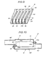
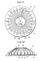
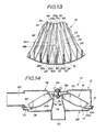
- Figs. 11 to 14 illustrate a third embodiment of the fluid filter (air filter) similar to the first embodiment of Figs. 1 to 5C mainly with the exception that the filter medium 16 is generally of the frusto-conical shape.
- the length of the outer bonded section B 1 is smaller than that of the inner bonded section B 2 , so that the length of the edge 30 of the outer inclined wall 28 is larger than that of the edge 42 of the inner inclined wall 40 as seen from Figs. 13 and 14.
- the length of the first and second oblique score lines 32a, 32b defining the outer inclined wall 28 is larger than those in the first embodiment.
- Such a filter medium 16 is incorporated with the outer and inner resilient seal members 64, 66 to produce the filter element 14 as shown in Figs. 11, 12 and 14, in which the outer peripheral section of each outer inclined wall 28 and the lower-most portion of the outer bonded section B 1 are embedded in the outer sealing member 64 while the inner peripheral section of each inner inclined wall 40 and the lower-most section of the inner bonded section B 2 are embedded in the inner sealing member 66.
- the filter element 14 is securely and sealingly installed in the casing 10 in such a manner that the outer sealing member 64 is securely put between the annular flanges 72, 82 of the body 68 and the cover 78 while the inner sealing member 66 is securely put between the body side annular flange 76 and the depressed flat portion 78a of the cover 78 as shown in Fig. 14.
- the casing 12 is formed deeper to house the frusto-conical filter element 14, thus obtaining dirty and clean side spaces of larger volumes, formed upstream and downstream of the filter element 14, respectively, within the casing 12.
- Fig. 15 illustrates an essential part of a fourth embodiment of the fluid filter (air filter) according to the present invention, which is similar to the third embodiment with the exception that a rigid annular plate 100 is embedded in the inner annular resilient sealing member 66.
- This sealing member 66 is inserted together with a part of the filter medium 10 during molding of the inner sealing member 66.
- the inner sealing member 66 may be directly attached to the bridge member 74 or directly put between the bridge member 74 and the inner surface of the cover 78 to be secured in position, for example, by means of bolt-and-nut connection.
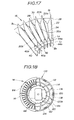
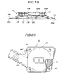
- Figs. 16 to 21 illustrate a fifth embodiment of the fluid filter (air filter) according to the present invention, which is similar to the third embodiment of Figs. 11 to 14 mainly except for provision of a generally frusto-conical skeletal support structure 110 on which the generally frusto-conical filter medium 16 is securely disposed to form the filter element 14.
- the support structure 110 of this embodiment is in one-piece construction.
- each inner inclined wall 40 consists of a triangular section 40a and a rectangular section 40b.
- the rectangular section 40b is defined by two nearly parallel score lines L 1 , L 2 which form part of third and fourth oblique score lines 44a, 44b, respectively.
- the score lines L 1 , L 2 may be not parallel.
- the parallel score lines L 1 , L 2 have the same length and extend nearly parallel (or with a slight inclination) with the upper main score 22 of the pleat 18 formed with the rectangular section 40b, thereby making the rectangular section generally flat or generally parallel with the upper main score line 22.
- the support structure 110 is generally in the frusto-conical shape and includes an annular beam section 112.
- a plurality of straight beam sections 114 are integrally connected with the annular beam section 112.
- the filter medium 16 is mounted on the beam sections 112, 114.
- each straight beam section 114 is formed inclined relative to an imaginary radial vertical plane (not identified) in order that the downwardly-pointing pleat is prevented from covering with the straight beam section 114 and that many downwardly-pointing pleats can be supported by each straight beam section 114.
- Each straight beam section 114 has a rectangular cross-section or may has a circular cross-section in order to reduce flow resistance of the fluid passing through the filter element 14.
- a lower support ring 116 is so provided to be integrally connected with the lower ends of the respective straight beam sections 114.
- the lower support ring 116 is formed with a plurality of long projections 118a and a plurality of short projections 118b.
- Each long projection 118a extends along the lower support ring 116 and located midway between two portions to which the lower ends of the adjacent two straight beam sections 114 are integrally connected.
- Each short projection 118b is located at a portion to which the lower end of each straight beam section 114.
- the lower support ring 116 is formed with a plurality of long through-holes 120a and a plurality of short through-holes 120b.
- Each long through-hole 120a is positioned near the long projection 118a and on the side of the outer periphery of the lower support ring 116.
- Each short through-hole 120b is positioned near the short projection 118b and on the side of the outer periphery of the lower support ring 116.
- a upper support ring 120 is so provided as to be integrally connected with the upper ends of the respective straight beam sections 116.
- the upper support ring 120 is integrally formed with a plurality of vertically extending pillar sections 122 each of which has a outwardly projecting bend portion 122a.
- an upper rid section 124 is provided inside the pillar sections 122 in such a manner as to be integrally connected with the pillar sections 122.
- the upper rid section 124 is formed at its central part with a bolt-hole 124a.
- the outer annular resilient sealing member 64 is made of a foamed polyurethane and so provided that the lower part of the outer peripheral section of the filter medium 16 and the support structure lower support ring 116 are embedded in the sealing member 64. It is to be noted that the peripheral section lower part of the filter medium 16 is in contact and engaged with the projections 118a, 118b as best seen from Fig. 16.
- flowable polyurethane having a relatively high vicosity is poured into a metallic mold located at a predetermined position in which the filter medium 16 and the support structure lower support ring 116 are located in respective predetermined positions. The thus poured polyurethane is foamed and thereafter solidified.
- the projections 118a, 118b are formed intermittent along the lower support ring 116 in order that the flowable polyurethane can be sufficiently introduced from the upper side to the lower side of the lower support ring 116.
- the through-holes 120a, 120b are also provided for the same purpose, thereby facilitating supply of the flowable polyurethane from the upper side to the lower side of the lower support ring 116.
- the arrangement of projections 118a, 118b and the through-holes 120a, 120b contributes to facilitating the molding of the outer sealing member 64 and to formation of the integral structure of the outer sealing member 64 in which the sealing member upper part located on the lower support ring and the sealing member lower part located beneath the same are securely integral with each other, thus preventing the sealing member 64 from being peeled off from the lower support ring 116 while avoiding failed fluid seal.
- the annular resilient inner sealing member 66 is made of a foamed polyurethane and so provided that the upper part of the inner peripheral section of the filter medium 16 and the upper portion of the support structure pillar sections 122 are embedded in inner sealing member 66. It will be understood that the outer peripheral portion of the upper rid section 124 is also embedded in the upper sealing member 66.
- the inner sealing member 66 is molded similarly to the outer sealing member 64. It will be understood that, in this embodiment, the bent portion 122a of each pillar section 122 embedded in the inner sealing member 66 secures the connection between the sealing member 66 and the support structure 120, thereby preventing the sealing member 66 from being peeled off from the support structure 110 while avoiding failed fluid seal.
- the filter element 14 is securely and sealing installed within the casing 12 formed of a plastic material.
- the casing 12 includes a rectangular box-shaped body 68' formed at its central part with an air outlet opening 68'a.
- a rectangular box-shaped cover 78' is engaged with the body 68' and secured in position by means of bolts, thus incorporating the body 68' and the cover 78'.
- the body 68' is integrally formed with an air inlet pipe cover 78'a.
- An air inlet pipe 80 1 is secured to the incorporated body 68' and cover 78' so that the inside of the inlet pipe 80 1 is communicated with the inside of the casing 12 through an opening 128 formed in the casing 12.
- the air inlet pipe 80 1 is formed by incorporating upper and lower counterparts 80'a, 80'b by means of press fit.
- a vacuum motor or vacuum-operated actuator 130 is mounted on the air inlet pipe upper counterpart 80'a and mechanically connected to a damper valve 132 adapted to open or close a heated air intake pipe 134 through which heated air is supplied to the the air inlet pipe 80'.
- the filter element 14 is secured in position in such a manner that the support structure upper rid section 124 is forced to a retainer 136 fixed to the body 68' by means of a center bolt 138 passing through the cover 78' and located in the bolt-hole 124a of the upper rid section 124.
- the outer sealing member 64 is disposed to be in tight contact with the inner surface of the body 68' under the action of downwardly extending parts of the cover 78' and of the air inlet pipe 80'.
- the inner sealing member 66 is in tight contact with the inner surface of the cover 78 1. It will be understood that the filter element 14 can be installed without any trouble even within such a flat casing 12.
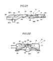
- Fig. 22 illustrates a sixth embodiment of the fluid filter (air filter) according to the present invention which is similar to the fifth embodiment of Figs. 16 and 21.
- the filter element 14 as same as in the fifth embodiment is securely and sealingly disposed within the casing 12.
- the casing 12 consists of the relatively flat body 68 1 formed at its centeral part with the-air outlet opening 68'a.
- the generally bowl-like cover 78 1 provided with the air inlet pipe 80' is securely mounted on the body 68' upon tightening the bolt 138 engaged with the retainer 136.
- a spacer member 150 is interposed between the cover 78 1 and the upper rid section 124 of the filter medium support structure 110, so that the upper rid section 124 is brought into tight contact with the retainer 136 while providing a fluid tight seal for the bolt-hole 124.
- the outer sealing member 64 is disposed to be in tight contact with the peripheral section of the body 68' under the pressing action of the lower peripheral section of the cover 78'. Accordingly, as illustrated, air sucked into the air filter casing 12 flows, for example, along paths A 1 , A 2 and A3 to be fed to the engine during engine operation.
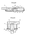
- Fig. 23 illustrates a seventh embodiment of the fluid filter (air filter) according to the present invention which is similar to the sixth embodiment of Fig. 22 with the exception that the annular support beam 112 section and the straight support beam sections 114 of the skeletal filter medium support structure 110' are arranged to be generally flat.
- the filter medium 16 lies flat on the thus flatly arranged beam sections 112, 114 as shown in the drawing.
- air sucked to the inside of the casing 12 flow along paths B 1 , B 2 and B 3 to be supplied to the engine.
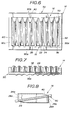
- Figs. 24 to 27 illustrate an eighth embodiment of the fluid filter (air filter) according to the present invention.
- the filter element 14 is securely and sealingly disposed within the casing 12 as shown in Fig. 1.
- the filter medium 16 of the filter element 14 is generally cylindrical so that the pleats 18 extend parallel with each other to have a first or upper end E1 and a second or lower end E 2 .
- the upper end E l contains the edge 30 of the first inclined wall 28 and the upper edge of each first bonded section B 1 .
- the lower end E 2 contains the edge 42 of each second inclined wall 40 and the lower edge of each second bonded section B 2 .
- each first inclined wall 28 consists of an isosceles-triangular section 28a and a generally rectangular section 28b containing the edge 30. It will be understood that the surface of the rectangular section 28b is inclined to that of the triangular section 28a.
- each second inclined wall 40 consists of an isosceles-triangular section 40a and a generally rectangular section 40b. The surface of the rectangular section 40b is inclined to that of the triangular section 40a.
- Fig. 26 shows a band-type filter material F similar to that of Fig. 5B with the exception that the filter material F is shown upside down relative to that of Fig. 5B.
- Fig. 26 depicts a pleating pattern of the filter material F to obtain the filter medium shown in Fig. 25, in which the scores a, a', a" indicated by the solid lines are depressed to form the downwardly-pointing pleats while the scores b, b', b" indicated by the broken lines are raised to form the upwardly-pointing pleats.
- the adhesive 52 is applied on the front side S 1 at the lower continuous end section 54a except for the sections each being put between the scores b, b".
- each of the scores a', a" is bent to have first and second portions P 1 , P 2 .
- the portions P 1 , P 1 of the a', a" define an isosceles-triangular area which corresponds to the isosceles-triangular section 28a of the first inclined wall 28 of the filter medium 16 shown in Fig. 25.
- the portions P 2 , P 2 of the scores a', a" define a rectangle-like area which corresponds to the generally triangular section 28b of the first inclined wall 28 of the filter medium 16 shown in Fig. 25. As shown, the portion P 2 of the scores a', a" is so formed that the extension thereof passes through a point where the score a intersects the lower edge of the upper continuous end section 54a. Similarly, each of the scores b', b" is bent to have third and fourth portions P 3 , P 4 .
- the portions P 3 , P 4 of the scores b', b" define an isosceles-triangular area which corresponds to the isosceles-triangular section 40a of the second inclined wall 40 of the filter medium 16 shown in Fig. 25.
- the portions P 4 , P 4 of the scores b', b" define a rectangle-like area which corresponds to the generally rectangular section 40b of the second inclined wall 40 of the filter medium 16 shown in Fig. 25.
- the portions P 4 of the scores b', b" is so formed that the extension (indicated by a dotted line) thereof passes through a point where the score b intersects the upper edge of the lower continuous end section 54a.
- the filter- material F is pleated along the scores patterned as shown in Fig. 26 to be shaped as shown in Fig. 27.
- the thus shaped filter material F is thereafter formed into the annular shape as shown in Fig. 25 by bonding the initial end and the terminal end of filter material F.
- the first (upper) annular resilient sealing member 64' is so provided that the generally rectangular section 28b of each first inclined wall 28 and the radially inward portion of each first bonded section B 1 are embedded in the upper sealing member 64'.
- the upper sealing member 64' extends radially inwardly and parallel with the upper end E I of the annular filter medium 16.
- the second (lower) annular resilient sealing member 66 1 is so provided that the generally rectangular section 40b of each second inclined wall 40 and the radially outward portion of each second bonded section B 2 are embedded in the lower sealing member 66'.
- the lower sealing member 66' extends radially outwardly and parallel with lower end E 2 .
- the upper sealing member 64' is secured through a packing 160 to the bridge 74 by tightening a center bolt 162 engaged with a bridge 164 fixed inside the air outlet pipe 70.
- the lower sealing member 66' is put between the outer peripheral sections of the body 68 and the cover 78 through a packing 166. Accordingly, air sucked through the air inlet pipe 80 flows as indicated by arrows and passes through the filter element 14 to be supplied through the air outlet pipe 70 to the engine.
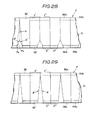
- Figs. 28 to 30 show a variety of pleating patterns of the filter material F to form annular filter medium 16 like one shown in Fig. 25.
- Fig. 28 The pattern of Fig. 28 is similar to that shown in Fig. 27 with the exception that the scores a', a" are omitted while the score a extends to reach the upper edge 56a of the filter material F.
- Fig. 29 The pattern of Fig. 29 is similar to that shown in Fig. 28 with the exception that the scores b, b l and b" are omitted and replaced with scores g, g' each extending from the filter material lower edge 56a to the lower edge of the upper continuous end section 54b.
- the scores g, g' define an isosceles-triangular area which corresponds to the second inclined wall 40 formed on the top of each pleat 18.
- Fig. 30 The pattern of Fig. 30 is similar to that of Fig. 27 with the exception that the scores a, a', a" are replaced with scores h, h' each extending from the filter material upper edge 56b to the upper edge of the lower continuous end section 54a.
- the scores h, h' defines an isosceles-triangular area corresponding to the first inclined wall 28.
- Fig. 31 illustrates a ninth embodiment of the fluid filter (air filter) according to the present invention.
- filter medium 16 similar to that of Fig. 25 (the eighth embodiment) is securely attached on the skeletal filter medium support structure 110 similar to that of Fig. 19 (the fifth embodiment) to form the filter element 14.
- the filter medium 16 of this embodiment is generally frusto-conical and located on the generally frusto-conical section 110a of the support structure 110.
- the inner peripheral section of the filter medium 16 at the first end E 1 is embedded in the first sealing member 64 1 in which the top section of the support structure 110 is embedded.
- the outer peripheral section of the filter medium 16 at the second end E 2 is embedded in the second sealing member 66' in which the bottom peripheral section of the support structure 110 is embedded.
- the thus configurated filter element 14 is secured and sealingly disposed in the deep bowl-like body 68' in such a manner that the second sealing member 66 1 is in tight contact with the inner surface of the body 68'.
- the body 68' is provided with the air inlet pipe 80 1 .
- the flat cover 78 is detachably installed to the body 68' by means of the bolt 150 engaged with the retainer 136. Accordingly, air sucked into the casing 12 flows along paths indicated by C 1 , C 21 and C 3 to be supplied to the engine.
- Fig. 32 illustrates a tenth embodiment of the fluid filter (air filter) according to the present invention which is similar to the ninth embodiment of Fig. 31 with the exception that the annular filter medium 16 is formed flat and securely disposed on the flat section 110a of the skeletal filter medium support structure 110 to form the filter element 14.
- the lower section of the first (inner) end E l of the annular filter medium 16 is securely connected through the first sealing member 64' to the inner section of the support structure 110.
- the upper section of the second (outer) end E 2 of the annular filter medium 16 is securely connected through the second sealing member 66' to the outer peripheral section of the support structure 110.
- air sucked into the - casing 12 flows along paths indicated by D 1 , D 2 , and D 3 and supplied to the engine.
- first and second inclined wall 28, 40 has been shown and described as being straight, it will be understood that the edge may be bent upwardly or downwardly upon increasing the length of the edge while decreasing the length of the first and second bonded sections B 1 . B 2 . Additionally, at least one of the first and second incliend walls 28, 40 may be cut off and therefor covered with the sealing member 64, 66. It will be appreciated that the angle formed between the first and second sides 20a, 20b of each pleat 18 is suitably selectable depending upon kind and amount of fluid to be filtered, and allowable space for the filter element, and that an additional seal member may be used in case where the seal members 64, 66 are formed of a material having no resiliency. Although only air filters have been shown and described as the embodiments according to the present invention, it will be appreciated that the principle of the present invention is applicable to a variety of filters such as lubricating oil, hydraulic fluid, and fuel filters used in automotive internal combustion engines.
Landscapes
- Chemical & Material Sciences (AREA)
- Chemical Kinetics & Catalysis (AREA)
- Physics & Mathematics (AREA)
- Geometry (AREA)
- Filtering Of Dispersed Particles In Gases (AREA)
Priority Applications (1)
| Application Number | Priority Date | Filing Date | Title |
|---|---|---|---|
| JP62078298A JP2566772B2 (ja) | 1986-06-13 | 1987-03-31 | ▲ろ▼過エレメント |
Applications Claiming Priority (8)
| Application Number | Priority Date | Filing Date | Title |
|---|---|---|---|
| JP130356/85 | 1985-06-15 | ||
| JP60130356A JPS61291015A (ja) | 1985-06-15 | 1985-06-15 | 濾過素子および濾過エレメント |
| JP218836/85 | 1985-09-30 | ||
| JP60218836A JPS6274416A (ja) | 1985-09-30 | 1985-09-30 | 濾過エレメント |
| JP1985184344U JPH0417215Y2 (de) | 1985-11-29 | 1985-11-29 | |
| JP184344/85U | 1985-11-29 | ||
| JP29738885A JPS62155916A (ja) | 1985-12-28 | 1985-12-28 | フイルタエレメント |
| JP297388/85 | 1985-12-28 |
Publications (2)
| Publication Number | Publication Date |
|---|---|
| EP0206182A1 true EP0206182A1 (de) | 1986-12-30 |
| EP0206182B1 EP0206182B1 (de) | 1990-03-14 |
Family
ID=27471531
Family Applications (1)
| Application Number | Title | Priority Date | Filing Date |
|---|---|---|---|
| EP86108140A Expired - Lifetime EP0206182B1 (de) | 1985-06-15 | 1986-06-13 | Fluidfilter mit gefaltetem Filtermedium |
Country Status (3)
| Country | Link |
|---|---|
| US (1) | US4710297A (de) |
| EP (1) | EP0206182B1 (de) |
| DE (1) | DE3669443D1 (de) |
Cited By (8)
| Publication number | Priority date | Publication date | Assignee | Title |
|---|---|---|---|---|
| GB2209354A (en) * | 1987-08-31 | 1989-05-10 | Tsuchiya Seisakusho | Filter medium forming system and process |
| GB2223695A (en) * | 1988-10-11 | 1990-04-18 | Sabre Safety Ltd | Making radially pleated filter elements |
| US4940500A (en) * | 1987-08-31 | 1990-07-10 | Tsuchiya Mfg. Co., Ltd. | Filter medium forming system and process |
| EP0656225A1 (de) * | 1993-10-28 | 1995-06-07 | W.L. GORE & ASSOCIATES GmbH | Filterpatrone |
| GB2352195A (en) * | 1999-06-24 | 2001-01-24 | Nationwide Filter Company | Strengthened pleated filter |
| EP3417751A1 (de) * | 2017-05-29 | 2018-12-26 | BSH Hausgeräte GmbH | Filteranordnung mit einem flachfilter |
| US11224833B2 (en) | 2019-03-27 | 2022-01-18 | Donaldson Company, Inc. | Particle separator filter with an axially extending flow face |
| US11364462B2 (en) | 2017-09-25 | 2022-06-21 | Donaldson Company, Inc. | Filter assembly |
Families Citing this family (30)
| Publication number | Priority date | Publication date | Assignee | Title |
|---|---|---|---|---|
| GB8607513D0 (en) * | 1986-03-26 | 1986-04-30 | Barrington R B | Filter for dry cleaning solvent |
| US5043000A (en) * | 1987-09-18 | 1991-08-27 | Toyo Roki Seizo K.K. | Air cleaner element and method of manufacturing the same |
| US5106397A (en) * | 1990-12-26 | 1992-04-21 | Ford Motor Company | Air cleaner/noise silencer assembly |
| US5128039A (en) * | 1991-06-04 | 1992-07-07 | Allied-Signal Inc. | Filter with delta wedge pleat |
| USD342990S (en) | 1991-12-13 | 1994-01-04 | Ford Motor Company | Air filter element |
| US5522909A (en) * | 1994-12-27 | 1996-06-04 | Purolator Products Na, Inc. | Air filter device |
| US5591329A (en) * | 1995-05-31 | 1997-01-07 | H-Tech, Inc. | Fluid filter with pleated septum |
| US5871641A (en) * | 1996-05-30 | 1999-02-16 | H-Tech, Inc. | Fluid filter with pleated septum |
| JP3347593B2 (ja) * | 1996-07-25 | 2002-11-20 | トヨタ自動車株式会社 | ディーゼルエンジン用パティキュレートトラップ |
| JP3488589B2 (ja) * | 1997-02-10 | 2004-01-19 | 株式会社共立 | エアークリーナ |
| FR2802116B1 (fr) | 1999-12-10 | 2002-05-03 | Maco Pharma Sa | Unite de filtration sterile d'un fluide,notamment le sang |
| US6482247B2 (en) * | 2000-06-23 | 2002-11-19 | Nelson Industries, Inc. | Multi-panel fluid filter with equalized contaminant passages |
| US6375700B1 (en) * | 2000-06-23 | 2002-04-23 | Nelson Industries, Inc. | Direct flow filter |
| US20040074215A1 (en) * | 2000-11-10 | 2004-04-22 | Carlo Cocconi | Method for making an air filter |
| DE10061479B4 (de) * | 2000-12-08 | 2007-08-02 | Carl Freudenberg Kg | Verfahren zur Herstellung eines Filtereinsatzes |
| US6800194B1 (en) * | 2001-09-26 | 2004-10-05 | Dana Corporation | Low waste liquid filter |
| US6966940B2 (en) | 2002-04-04 | 2005-11-22 | Donaldson Company, Inc. | Air filter cartridge |
| KR20050098922A (ko) | 2003-02-11 | 2005-10-12 | 도널드선 컴파니 인코포레이티드 | 에어 크리너 배열과 서비스가능한 필터 구성 요소 및 방법 |
| DE102004001718A1 (de) * | 2004-01-13 | 2005-08-04 | Robert Bosch Gmbh | Endlosfaltfilter für Partikelfilterung |
| EP1804955B1 (de) * | 2004-08-04 | 2011-01-26 | Daimler AG | Partikelfilter |
| US20110197556A1 (en) | 2004-11-02 | 2011-08-18 | Baldwin Filters, Inc. | Filter element |
| EP1850943B1 (de) | 2005-01-13 | 2013-06-05 | Donaldson Company, Inc. | Luftfilterpatrone und luftreinigungsanordnung |
| DE102005022419A1 (de) * | 2005-05-14 | 2006-11-16 | Purem Abgassysteme Gmbh & Co. Kg | Partikelfilter |
| WO2012096583A2 (en) | 2011-01-11 | 2012-07-19 | Secura-Nova Spółka Z Ograniczoną Odpowiedzialnością | Pleated filter and a method for manufacturing of pleated filters |
| WO2014018528A1 (en) | 2012-07-25 | 2014-01-30 | Baldwin Filters, Inc. | Filter housing, fluted filter and safety filter |
| US10112130B2 (en) | 2012-10-09 | 2018-10-30 | Donaldson Company, Inc. | Self-supporting folded sheet material, filter elements, and methods |
| US10105632B2 (en) | 2014-04-09 | 2018-10-23 | Donaldson Company, Inc. | Self-supporting folded sheet material, filter elements, and methods |
| US10315147B2 (en) | 2014-09-15 | 2019-06-11 | Donaldson Company, Inc. | Filter cartridges; air cleaner assemblies; housings; features; components; and, methods |
| US10682597B2 (en) | 2016-04-14 | 2020-06-16 | Baldwin Filters, Inc. | Filter system |
| CN109414640B (zh) * | 2016-07-13 | 2021-10-08 | 康明斯过滤Ip公司 | 具有锥形周边的过滤器元件 |
Citations (6)
| Publication number | Priority date | Publication date | Assignee | Title |
|---|---|---|---|---|
| GB961806A (en) * | 1962-01-31 | 1964-06-24 | American Air Filter Co | Improvements in and relating to filters |
| DE2342155B2 (de) * | 1973-08-21 | 1977-04-28 | Purolator Filter GmbH, 7110 Öhringen | Verfahren zur herstellung eines runden, flachen filtereinsatzes |
| DE2715679A1 (de) * | 1977-04-07 | 1978-10-12 | Andrasfalvy | Asymmetrisches luftfilter fuer verbrennungskraftmaschinen, insbesondere in kraftfahrzeugen |
| GB2030464A (en) * | 1978-09-21 | 1980-04-10 | Gen Motors Ltd | Fluid filter elements and their manufacture |
| DE2937757A1 (de) * | 1979-09-19 | 1981-04-09 | Degussa Ag, 6000 Frankfurt | Mechanisch stabile siebgewebeanordnung aus metall |
| SU831143A1 (ru) * | 1979-03-28 | 1981-05-23 | Дальневосточное Высшее Инженерноеморское Училище Им. Адмиралаг.И.Невельского | Фильтрующий элемент |
Family Cites Families (9)
| Publication number | Priority date | Publication date | Assignee | Title |
|---|---|---|---|---|
| US2410371A (en) * | 1943-02-08 | 1946-10-29 | Vokes Cecil Gordon | Filter |
| US2823760A (en) * | 1955-05-10 | 1958-02-18 | Garrett Corp | Water separator |
| US3235633A (en) * | 1962-04-02 | 1966-02-15 | Gen Motors Corp | Method of molding filter end caps |
| GB1274355A (en) * | 1970-01-28 | 1972-05-17 | Gen Motors Ltd | Filter elements for liquid filters |
| US3640396A (en) * | 1970-04-03 | 1972-02-08 | Fram Corp | Filter |
| GB1426173A (en) * | 1972-03-11 | 1976-02-25 | Gen Motors Ltd | Fluid filter elements |
| US3859068A (en) * | 1972-05-09 | 1975-01-07 | Tenneco Inc | Pleated air filter |
| CH597866A5 (de) * | 1975-11-25 | 1978-04-14 | Castella Pierre De | |
| US4303426A (en) * | 1980-03-14 | 1981-12-01 | Robert Battis | Automobile air filter having replaceable and readily disposable filter element |
-
1986
- 1986-03-28 US US06/845,842 patent/US4710297A/en not_active Expired - Lifetime
- 1986-06-13 DE DE8686108140T patent/DE3669443D1/de not_active Expired - Fee Related
- 1986-06-13 EP EP86108140A patent/EP0206182B1/de not_active Expired - Lifetime
Patent Citations (6)
| Publication number | Priority date | Publication date | Assignee | Title |
|---|---|---|---|---|
| GB961806A (en) * | 1962-01-31 | 1964-06-24 | American Air Filter Co | Improvements in and relating to filters |
| DE2342155B2 (de) * | 1973-08-21 | 1977-04-28 | Purolator Filter GmbH, 7110 Öhringen | Verfahren zur herstellung eines runden, flachen filtereinsatzes |
| DE2715679A1 (de) * | 1977-04-07 | 1978-10-12 | Andrasfalvy | Asymmetrisches luftfilter fuer verbrennungskraftmaschinen, insbesondere in kraftfahrzeugen |
| GB2030464A (en) * | 1978-09-21 | 1980-04-10 | Gen Motors Ltd | Fluid filter elements and their manufacture |
| SU831143A1 (ru) * | 1979-03-28 | 1981-05-23 | Дальневосточное Высшее Инженерноеморское Училище Им. Адмиралаг.И.Невельского | Фильтрующий элемент |
| DE2937757A1 (de) * | 1979-09-19 | 1981-04-09 | Degussa Ag, 6000 Frankfurt | Mechanisch stabile siebgewebeanordnung aus metall |
Cited By (12)
| Publication number | Priority date | Publication date | Assignee | Title |
|---|---|---|---|---|
| GB2209354A (en) * | 1987-08-31 | 1989-05-10 | Tsuchiya Seisakusho | Filter medium forming system and process |
| US4940500A (en) * | 1987-08-31 | 1990-07-10 | Tsuchiya Mfg. Co., Ltd. | Filter medium forming system and process |
| GB2209354B (en) * | 1987-08-31 | 1991-10-30 | Tsuchiya Seisakusho | Filter medium forming system and process |
| GB2223695A (en) * | 1988-10-11 | 1990-04-18 | Sabre Safety Ltd | Making radially pleated filter elements |
| EP0656225A1 (de) * | 1993-10-28 | 1995-06-07 | W.L. GORE & ASSOCIATES GmbH | Filterpatrone |
| GB2352195A (en) * | 1999-06-24 | 2001-01-24 | Nationwide Filter Company | Strengthened pleated filter |
| GB2352195B (en) * | 1999-06-24 | 2003-11-26 | Nationwide Filter Company | High flowrate filter |
| EP3417751A1 (de) * | 2017-05-29 | 2018-12-26 | BSH Hausgeräte GmbH | Filteranordnung mit einem flachfilter |
| US11364462B2 (en) | 2017-09-25 | 2022-06-21 | Donaldson Company, Inc. | Filter assembly |
| US12330108B2 (en) | 2017-09-25 | 2025-06-17 | Donaldson Company, Inc. | Filter assembly |
| US11224833B2 (en) | 2019-03-27 | 2022-01-18 | Donaldson Company, Inc. | Particle separator filter with an axially extending flow face |
| US11801468B2 (en) | 2019-03-27 | 2023-10-31 | Donaldson Company, Inc. | Particle separator filter with an axially extending flow face |
Also Published As
| Publication number | Publication date |
|---|---|
| DE3669443D1 (de) | 1990-04-19 |
| US4710297A (en) | 1987-12-01 |
| EP0206182B1 (de) | 1990-03-14 |
Similar Documents
| Publication | Publication Date | Title |
|---|---|---|
| US4710297A (en) | Fluid filter with pleated filter medium | |
| US11833463B2 (en) | Air cleaner assemblies | |
| US5273560A (en) | Filter element and method for producing the same | |
| CN1754612A (zh) | 有密封衬垫的板过滤器 | |
| US5043000A (en) | Air cleaner element and method of manufacturing the same | |
| US2968361A (en) | Filters for gases | |
| JPS5938005B2 (ja) | 変速機用流体フイルタ | |
| JPH0557011B2 (de) | ||
| JPH01207112A (ja) | フィルタエレメントの製造方法 | |
| JPH0527441B2 (de) | ||
| JPH0414099Y2 (de) | ||
| JPS5892435A (ja) | 流体清浄器 | |
| JPH0414100Y2 (de) | ||
| JPS6382406U (de) | ||
| JPS63310617A (ja) | 流体用濾過体 | |
| JPS6240666Y2 (de) | ||
| JPS6313774Y2 (de) | ||
| JPS63214312A (ja) | 環状笠形の濾過エレメント | |
| JPH0337697Y2 (de) | ||
| JPH0414101Y2 (de) | ||
| DE2739205C2 (de) | Topfförmiges Gasfilter | |
| JPH061219Y2 (ja) | エアクリーナ | |
| JPH0751127Y2 (ja) | 濾過エレメント | |
| JPH0113532Y2 (de) | ||
| JPS635124B2 (de) |
Legal Events
| Date | Code | Title | Description |
|---|---|---|---|
| PUAI | Public reference made under article 153(3) epc to a published international application that has entered the european phase |
Free format text: ORIGINAL CODE: 0009012 |
|
| 17P | Request for examination filed |
Effective date: 19860613 |
|
| AK | Designated contracting states |
Kind code of ref document: A1 Designated state(s): BE DE FR GB NL |
|
| 17Q | First examination report despatched |
Effective date: 19880427 |
|
| GRAA | (expected) grant |
Free format text: ORIGINAL CODE: 0009210 |
|
| AK | Designated contracting states |
Kind code of ref document: B1 Designated state(s): BE DE FR GB NL |
|
| REF | Corresponds to: |
Ref document number: 3669443 Country of ref document: DE Date of ref document: 19900419 |
|
| ET | Fr: translation filed | ||
| PLBE | No opposition filed within time limit |
Free format text: ORIGINAL CODE: 0009261 |
|
| STAA | Information on the status of an ep patent application or granted ep patent |
Free format text: STATUS: NO OPPOSITION FILED WITHIN TIME LIMIT |
|
| 26N | No opposition filed | ||
| REG | Reference to a national code |
Ref country code: GB Ref legal event code: IF02 |
|
| PGFP | Annual fee paid to national office [announced via postgrant information from national office to epo] |
Ref country code: BE Payment date: 20020621 Year of fee payment: 17 |
|
| PGFP | Annual fee paid to national office [announced via postgrant information from national office to epo] |
Ref country code: NL Payment date: 20020624 Year of fee payment: 17 |
|
| PG25 | Lapsed in a contracting state [announced via postgrant information from national office to epo] |
Ref country code: BE Free format text: LAPSE BECAUSE OF NON-PAYMENT OF DUE FEES Effective date: 20030630 |
|
| BERE | Be: lapsed |
Owner name: *KABUSHIKI KAISHA TSUCHIYA SEISAKUSHO Effective date: 20030630 |
|
| PG25 | Lapsed in a contracting state [announced via postgrant information from national office to epo] |
Ref country code: NL Free format text: LAPSE BECAUSE OF NON-PAYMENT OF DUE FEES Effective date: 20040101 |
|
| NLV4 | Nl: lapsed or anulled due to non-payment of the annual fee |
Effective date: 20040101 |
|
| PGFP | Annual fee paid to national office [announced via postgrant information from national office to epo] |
Ref country code: GB Payment date: 20040528 Year of fee payment: 19 |
|
| PGFP | Annual fee paid to national office [announced via postgrant information from national office to epo] |
Ref country code: FR Payment date: 20040618 Year of fee payment: 19 |
|
| PGFP | Annual fee paid to national office [announced via postgrant information from national office to epo] |
Ref country code: DE Payment date: 20040730 Year of fee payment: 19 |
|
| PG25 | Lapsed in a contracting state [announced via postgrant information from national office to epo] |
Ref country code: GB Free format text: LAPSE BECAUSE OF NON-PAYMENT OF DUE FEES Effective date: 20050613 |
|
| PG25 | Lapsed in a contracting state [announced via postgrant information from national office to epo] |
Ref country code: DE Free format text: LAPSE BECAUSE OF NON-PAYMENT OF DUE FEES Effective date: 20060103 |
|
| PG25 | Lapsed in a contracting state [announced via postgrant information from national office to epo] |
Ref country code: FR Free format text: LAPSE BECAUSE OF NON-PAYMENT OF DUE FEES Effective date: 20060228 |
|
| GBPC | Gb: european patent ceased through non-payment of renewal fee |
Effective date: 20050613 |
|
| REG | Reference to a national code |
Ref country code: FR Ref legal event code: ST Effective date: 20060228 |