EP0207009A2 - Poignée amovible pour armes portatives - Google Patents
Poignée amovible pour armes portatives Download PDFInfo
- Publication number
- EP0207009A2 EP0207009A2 EP86830115A EP86830115A EP0207009A2 EP 0207009 A2 EP0207009 A2 EP 0207009A2 EP 86830115 A EP86830115 A EP 86830115A EP 86830115 A EP86830115 A EP 86830115A EP 0207009 A2 EP0207009 A2 EP 0207009A2
- Authority
- EP
- European Patent Office
- Prior art keywords
- handle
- hooking element
- sight
- spring
- rear sight
- Prior art date
- Legal status (The legal status is an assumption and is not a legal conclusion. Google has not performed a legal analysis and makes no representation as to the accuracy of the status listed.)
- Granted
Links
- 230000000903 blocking effect Effects 0.000 claims description 4
- 230000013011 mating Effects 0.000 claims description 2
- 210000003423 ankle Anatomy 0.000 claims 1
- 239000011521 glass Substances 0.000 description 2
- 230000008878 coupling Effects 0.000 description 1
- 238000010168 coupling process Methods 0.000 description 1
- 238000005859 coupling reaction Methods 0.000 description 1
- 238000009432 framing Methods 0.000 description 1
Images

Classifications
-
- F—MECHANICAL ENGINEERING; LIGHTING; HEATING; WEAPONS; BLASTING
- F41—WEAPONS
- F41C—SMALLARMS, e.g. PISTOLS, RIFLES; ACCESSORIES THEREFOR
- F41C33/00—Means for wearing or carrying smallarms
- F41C33/08—Handles for carrying smallarms
-
- F—MECHANICAL ENGINEERING; LIGHTING; HEATING; WEAPONS; BLASTING
- F41—WEAPONS
- F41G—WEAPON SIGHTS; AIMING
- F41G1/00—Sighting devices
- F41G1/06—Rearsights
- F41G1/16—Adjusting mechanisms therefor; Mountings therefor
-
- F—MECHANICAL ENGINEERING; LIGHTING; HEATING; WEAPONS; BLASTING
- F41—WEAPONS
- F41G—WEAPON SIGHTS; AIMING
- F41G1/00—Sighting devices
- F41G1/32—Night sights, e.g. luminescent
Definitions
- the present invention relates to a removable handle with auxiliary sight elements, in particular for portable automatic weapons.
- the object of the invention is to provide a handle applicable to automatic weapons by using the fixing means and support of the type already provided on these weapons to mount, for example, a holder glasses.
- Another object of the invention is to provide a handle removably mounted on portable automatic weapons without influencing the line of sight, the handle having one or more longitudinal openings or slots for free access and good visibility of the means also when the handle is attached to the weapon.
- Yet another object of the invention is to provide a handle for portable automatic weapons also provided with auxiliary aiming means. Particularly obvious and possibly luminous to allow the aiming also in poor visibility conditions or in any case in critical conditions for a satisfactory use of the normal line of sight of the weapon.
- this invention relates to a removable handle, in particular for portable automatic weapons provided with a rear sight and a front hooking element remote from the rear sight, this handle comprising a body having at least one opening longitudinal horizontally aligned with the rear sight, a spring-loaded dowel which fits into the notch or seat provided in the front sight of the rear sight, a portion mating with interlocking with the attachment element fixed to the body of the weapon, and a locking bolt cooperating with this hooking element to prevent longitudinal movements and accidental detachment of the handle.
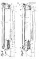
- the drawing shows the body 1) of an automatic rifle provided with a handle 2) to facilitate the taking and the transport of the weapon.
- On the body 1) of the weapon there is a notch or sight 3) and an element before attachment 4), for example with dovetail or having another suitable section.
- the notch or target notch 3) has a handlebar 3 ') with a front part 3 ") projecting having a hollow or seat 5) open towards the hooking element 4), the latter being in turn oriented logitudinally on and relative to the body of the weapon.
- the handle 2 is composed of a body 6) with one or more transverse openings 7) horizontally aligned with the rear sight 3) to allow correct and complete visibility of the line of sight of the weapon.
- a notch 8 intended to couple, in axial direction, with the front projection 3 ") of the handlebar 3 ') of the rear sight 3). from the notch a hole 9) is used to house and guide a dowel 10) subject to the action of a spring 10 ') and intended to extend into the projection 3 ") of the handlebar 3) of the rear sight 3 ).
- the body 6) of the handle 2) has a dovetail seat 11) or of another suitable section, intended to couple, in longitudinal direction, with the element before attachment 4) fixed to the body of the weapon.
- a blocking bolt 12 On the front head of the handle body 2) is mounted and guided, with a pre-established angle of incidence on the hooking element 4), a blocking bolt 12).
- this lock 12) for blocking has a window 12 ') coinciding with the openings 7) of the handle and it is subject to the action of a spring 13) which keeps it normally displaced towards the element d 'hooking 4), its maximum downward movement being limited by a locking pin 14) placing itself in a recess 15) pressed into the body of the handle - v. the detail in Fig. 5 -.
- the latch 12 has, in its middle part, a grip wing 16) for its manual operation and, below, a drawing plane 17) interacting with a head plane of the hooking element 4) to block the handle after its application on the weapon and cancel movements and also axial play.
- auxiliary line of sight constituted, for example, by two framing points 18) at the rear end of the handle and by a point opposite 19) at its opposite end, as shown in Fig. 1 of the drawing.
- These sights 18) -19) will be particularly obvious and possibly luminescent or luminous in order to consent to aiming the weapon also in poor visibility conditions and when the conventional line of sight of the weapon is not well usable.
Landscapes
- General Engineering & Computer Science (AREA)
- Engineering & Computer Science (AREA)
- Physics & Mathematics (AREA)
- Optics & Photonics (AREA)
- Toys (AREA)
- Aiming, Guidance, Guns With A Light Source, Armor, Camouflage, And Targets (AREA)
- Prostheses (AREA)
- Electric Vacuum Cleaner (AREA)
- Supports Or Holders For Household Use (AREA)
- Adornments (AREA)
- Telescopes (AREA)
- Steering Devices For Bicycles And Motorcycles (AREA)
- Support Of Aerials (AREA)
Abstract
Description
- La présente invention concerne une poignée amovible avec éléments de mire auxiliaires en particulier pour armes automatiques portatives.
- En matière d'armes automatiques portatives telles que les mitrailleuses et les autres armes du même genre, d'une part il a été toujours considéré nécessaire d'y appliquer une poignée de prise pour en faciliter le transport, sans pourtant y ajouter des autres éléments et sans compromettre la ligne de mire.
- D'autre part,il y a déjà des mitrailleuses munies de moyens pour y appliquer un porte-lunette et consistant d'un creux ou siège enfoncé dans le guidon avec le cran de mire de l'arme et d'un élément d'accrochage fixé à la partie avant du corps de l'arme, c'est-à-dire à distance du guidon avec cran de mire. Le porte-lunette est muni d'une cheville à ressort qui s'enclenche dans ce creux ou siège et d'une portion s'encliquetant avec l'élément d'accrochage susmentionné. A accouplement effectué, la cheville à ressort est bloqué axialement pour empêcher le détachement accidentel du porte-lunette.
- Or, s'on monte un élément à poignée simplement comme un porte-lunette et au lieu de ceci, cet application n'est pas faisable, attendu qu'elle va interrompre la ligne de mire et empêcher le pointage de l'arme.
- Sur la base de de ces prémisses, le but de l'invention c'est de proposer une poignée applicable aux armes automatiques en utilisant les moyens de fixation et support du type déjà prévu sur ces armes pour y monter, par exemple, un porte-lunette.
- Un autre but de l'invention c'est de proposer une poignée montée de façon amovible sur les armes automatiques portatives sans influencer la ligne de mire, la poignée ayant une ou plusieures ouvertures ou fentes longitudinales pour un libre accès et une bonne visibilité des moyens de pointage aussi quand la poignée est fixée sur l'arme.
- Un autre but encore de l'invention c'est de proposer une poignée pour armes automatiques portatives munie aussi de moyens de pointage auxiliaires particulièrement évidents et éventuellement lu- minuex pour consentir le pointage aussi en conditions de visibilité mauvaise ou en tout cas en conditions critiques pour un emploi satisfaisant de la ligne de mire normale de l'arme.
- Dans ce but, cette invention concerne une poignée amovible, en particulier pour armes automatiques portatives munies d'un cran de mire et d'un élément d'accrochage avant à distance du cran de mire, cette poignée comprenant un corps ayant au moins une ouverture longitudinale horizontalement alignée au cran de mire, une cheville à ressort qui s'insère dans l'encoche ou siège prévu dans le guidon du cran de mire, une portion s'accouplant à emboîtement avec l'élément d'accrochage fixé au corps de l'arme, et un verrou de blocage coopérant avec cet élément d'accrochage pour empêcher les déplacements longitudinaux et un détachement accidentel de la poignée.
- Un exemple de réalisation de l'invention sera mieux expliqué ci-après par la description faite avec référence au dessin ci-joint, où:
- la Fig. 1 montre une vue perspective arrière de la poignée;
- la Fig. 2 montre une vue perspective avant de la poignée;
- la Fig. 3 montre une section longitudinale de la poignée pendant son montage ou démontage sur l'arme;
- la Fig. 4 montre une section longitudinale de la poignée fixée à l'arme; et
- la Fig. 5 montre un détail agrandi du verrou d'enclenchement.
- Le dessin montre le corps 1) d'un fusil automatique muni d'une poignée 2) pour faciliter la prise et le transport de l'arme. Sur le corps 1) de l'arme il y a un cran de mire ou oeilleton 3) et un élément avant d'accrochage 4), par exemple à queu d'aronde ou ayant une autre section appropriée. Le cran ou encoche de mire 3) présente un guidon 3') avec une partie avant 3") en saillie présentant un creux ou siège 5) ouvert vers l'élément d'accrochage 4), ce dernier étant à tour orienté logitudinalement sur et par rapport au corps de l'arme.
- La poignée 2) est composée d'un corps 6) avec une ou plusieures ouvertures transversales 7) horizontalement alignées au cran de mire 3) pour consentir une visibilité correcte et complète de la ligne de mire de l'arme.
- A l'extrémité arrière du corps de la poignée, au-dessous du plan des ouvertures 7), il y a une encoche 8) destinée à s'accoupler, en direction axiale, avec la saillie avant 3") du guidon 3') du cran de mire 3). En correspondance de l'encoche un trou 9) sert à loger et guider une cheville 10) sujette à l'action d'un ressort 10') et destinée à s'étendre dans la sallie 3") du guidon 3) du cran de mire 3). A la base de sa partie avant le corps 6) de la poignée 2) présente un siège à queu d'aronde 11) ou d'autre section appropriée, destiné à s'accoupler, en direction longitudinale, avec l'élément avant d'accrochage 4) fixé au corps de l'arme. Sur la tête avant du corps de la poignée 2) est monté et guidé, avec un angle pré-établi d'incidence sur l'élément d'accrochage 4), un verrou de blocage 12).
- Comme montre le dessin, ce verrou 12) de blocage présente une fenêtre 12') coïncidant avec les ouvertures 7) de la poignée et il est sujet à l'action d'un ressort 13) que le maintient normalement déplacé vers l'élément d'accrochage 4), son déplacement maximal vers le bas étant limité par une cheville d'arrêt 14) se plaçant dans un creux 15) enfoncé dans le corps de la poignée - v. le détail en Fig. 5 -.
- En outre, le verrou 12) présente, dans sa partie moyenne, une aile de prise 16) pour sa manoeuvre manuelle et, au-dessous, un plan de tirage 17) interageant avec un plan de tête de l'élément d'accrochage 4) pour bloquer la poignée après son application sur l'arme et annuler les mouvements et aussi les jeux axiaux.
- Pour appliquer la poignée 2) à l'arme il faut loger la cheville 10) dans le creux ou siège 5) et déplacer la poignée en arrière en opposition à l'action du ressort 10') de la cheville 10) de façon à prédisposer le siège 11) pour son assemblage en queu d'aronde, en direction axiale, avec l'élément d'accrochage 4) et, enfin, déplacer en avant la poignée à l'aide du ressort 10') jusqu'à ce que le verrou 12), poussé par le ressort 13), va engager le plan de tirage 17) à la tête de l'élément d'accrochage 4). La condition de fixage de la poignée 2) est représentée dans les Figures 3 et 5 du dessin, qui montrent comme les actions contrastantes de la cheville à ressort 10)-10') d'un côté et du verrou 12) de l'autre côté consentent le blocage axial de la poignée en empêcheant tout mouvement ou son démontage ou détachement accidentel et incontrôlé. Une fois montée, la poignée facilite la prise et le transport de l'arme sans empêcher, d'autre part, grâce aux ouvertures longitudinales transversales 7), l'emploi correct de la ligne de mire.
- Dans la partie supérieure de la poignée 2) il est aussi possible de prévoir avantageusement une ligne de mire auxiliaire constituée, par exemple, par deux points d'encadrement 18) à l'extrémité arrière de la poignée et par un point en face 19) à son extrémité opposée, comme montre la Fig. 1 du dessin.
- Ces points de mire 18)-19) seront particulièrement évidents et éventuellement luminescents ou lumineux pour consentir un pointage de l'arme aussi en conditions de visibilité mauvaise et quand la ligne de mire conventionnelle de l'arme n'est pas bien utilisable.
- Pour le démontage de la poignée 2) il suffit d'agir sur l'aile 16) du verrou 12) pour le déplacer vers le haut et détacher son plan de tirage 17) de l'élément d'accrochage 4). Après ça, la poignée peut être déplacée en arrière pour la libérer de l'élément d'accrochage en répétant les opération de montage en succession inversée. Enfin, il faut la déplacer vers le haut pour la détacher du guidon du cran de mire.
Claims (5)
Priority Applications (1)
| Application Number | Priority Date | Filing Date | Title |
|---|---|---|---|
| AT86830115T ATE44313T1 (de) | 1985-05-24 | 1986-05-08 | Abnehmbarer tragegriff fuer handfeuerwaffen. |
Applications Claiming Priority (2)
| Application Number | Priority Date | Filing Date | Title |
|---|---|---|---|
| IT517385 | 1985-05-24 | ||
| IT05173/85A IT1186947B (it) | 1985-05-24 | 1985-05-24 | Maniglia asportabile con elementi di mira ausiliari,particolarmente per armi automatiche portatili |
Publications (3)
| Publication Number | Publication Date |
|---|---|
| EP0207009A2 true EP0207009A2 (fr) | 1986-12-30 |
| EP0207009A3 EP0207009A3 (en) | 1987-02-04 |
| EP0207009B1 EP0207009B1 (fr) | 1989-06-28 |
Family
ID=11118835
Family Applications (1)
| Application Number | Title | Priority Date | Filing Date |
|---|---|---|---|
| EP86830115A Expired EP0207009B1 (fr) | 1985-05-24 | 1986-05-08 | Poignée amovible pour armes portatives |
Country Status (8)
| Country | Link |
|---|---|
| US (1) | US4663878A (fr) |
| EP (1) | EP0207009B1 (fr) |
| AT (1) | ATE44313T1 (fr) |
| CA (1) | CA1265371A (fr) |
| DE (1) | DE3664162D1 (fr) |
| ES (1) | ES297034Y (fr) |
| IT (1) | IT1186947B (fr) |
| MA (1) | MA20687A1 (fr) |
Families Citing this family (14)
| Publication number | Priority date | Publication date | Assignee | Title |
|---|---|---|---|---|
| USD302454S (en) | 1986-09-22 | 1989-07-25 | O.F. Mossberg and Sons, Inc. | Combined firearm carrying handle and sight |
| USD303000S (en) | 1987-03-23 | 1989-08-22 | Tibor Tamas | Combined mount and support bracket for firearms |
| US4827652A (en) * | 1987-10-02 | 1989-05-09 | Martin Ernest J T | Cocking-bar, target-framing and range-finding, carrying, hanging and standing device |
| US4918823A (en) * | 1988-01-19 | 1990-04-24 | Santiago Julio A | Gunsight |
| US5070619A (en) * | 1988-01-19 | 1991-12-10 | Santiago Julio A | Gunsight |
| US4993158A (en) * | 1988-01-19 | 1991-02-19 | Santiago Julio A | Gunsight |
| ES2138876B1 (es) * | 1995-10-04 | 2000-09-16 | Otero De Nulas Isidoro | Fusil de asalto. |
| US6185854B1 (en) * | 1998-07-02 | 2001-02-13 | Insight Technology, Incorporated | Auxiliary device for a weapon and attachment thereof |
| AT12773U3 (de) * | 2012-06-29 | 2014-03-15 | Wilhelm Bubits | Pistole mit austauschbarer Kimme und Kimme für eine solche |
| US20160313090A1 (en) * | 2013-03-22 | 2016-10-27 | Orchard Arms Llc | Integral telescopic sight for firearms |
| US9372049B2 (en) * | 2014-06-03 | 2016-06-21 | Ncstar, Inc. | Handle sight |
| USD749185S1 (en) * | 2014-07-29 | 2016-02-09 | Ncstar, Inc. | Handle sight |
| US10837736B2 (en) * | 2018-12-18 | 2020-11-17 | Miklos Design Llc | Handgun with gunsight augmentation and enhanced pistol-grip and methods of use |
| US10605565B1 (en) * | 2019-01-16 | 2020-03-31 | WHG Properties, LLC | Adjustable rear sight for a firearm |
Family Cites Families (7)
| Publication number | Priority date | Publication date | Assignee | Title |
|---|---|---|---|---|
| DE962864C (de) * | 1952-10-17 | 1957-04-25 | Steyr Daimler Puch Ag | Zielfernrohrbefestigung fuer Gewehre |
| BE625029A (fr) * | 1961-11-18 | |||
| US3153856A (en) * | 1961-12-14 | 1964-10-27 | Thomas R Felix | Telescope sight mount |
| US3611607A (en) * | 1969-08-06 | 1971-10-12 | Thomas Donnell | Firearm conversion system |
| DE2023270C3 (de) * | 1970-05-13 | 1975-10-16 | Heckler & Koch Gmbh, 7238 Oberndorf | Handfeuerwaffe mit Traggriff |
| US3742636A (en) * | 1971-12-13 | 1973-07-03 | Fairchild Industries | Firearm having a carrying handle and associated rear sight |
| US4057003A (en) * | 1975-12-30 | 1977-11-08 | Atchisson Maxwell G | Open bolt conversion apparatus |
-
1985
- 1985-05-24 IT IT05173/85A patent/IT1186947B/it active
-
1986
- 1986-04-14 US US06/851,457 patent/US4663878A/en not_active Expired - Lifetime
- 1986-05-07 CA CA000508605A patent/CA1265371A/fr not_active Expired - Lifetime
- 1986-05-08 EP EP86830115A patent/EP0207009B1/fr not_active Expired
- 1986-05-08 AT AT86830115T patent/ATE44313T1/de not_active IP Right Cessation
- 1986-05-08 DE DE8686830115T patent/DE3664162D1/de not_active Expired
- 1986-05-09 ES ES1986297034U patent/ES297034Y/es not_active Expired
- 1986-05-20 MA MA20913A patent/MA20687A1/fr unknown
Also Published As
| Publication number | Publication date |
|---|---|
| EP0207009A3 (en) | 1987-02-04 |
| MA20687A1 (fr) | 1986-12-31 |
| IT8505173A0 (it) | 1985-05-24 |
| EP0207009B1 (fr) | 1989-06-28 |
| US4663878A (en) | 1987-05-12 |
| ES297034U (es) | 1988-07-01 |
| DE3664162D1 (en) | 1989-08-03 |
| CA1265371A (fr) | 1990-02-06 |
| IT1186947B (it) | 1987-12-16 |
| ATE44313T1 (de) | 1989-07-15 |
| ES297034Y (es) | 1989-02-01 |
Similar Documents
| Publication | Publication Date | Title |
|---|---|---|
| EP0207009B1 (fr) | Poignée amovible pour armes portatives | |
| US8793921B1 (en) | Tangent integrated tilt sight | |
| BE1000835A5 (fr) | Support de montage adaptable sur une arme a main. | |
| EP0161369A1 (fr) | Equerre de liaison pour réaliser l'assemblage de deux profilés | |
| BE1004441A6 (fr) | Appareil de pointage a faisceau laser. | |
| FR2544849A1 (fr) | Dispositif de verrouillage des canons et de la sous-garde interchangeable, commande par la cle de fermeture, pour fusils de chasse | |
| EP1304538A1 (fr) | Montage de dispositifs de visée d'armes | |
| EP0777847B1 (fr) | Dispositif d'adaptation d'un accessoire d'aide au tir sur une arme a feu individuelle | |
| FR2487062A1 (fr) | Revolver perfectionne | |
| EP2903702A1 (fr) | Systeme de fixation pour planche de surf des neiges de randonnee | |
| BE1001923A6 (fr) | Dispositif d'eclairement d'appareil de visee. | |
| FR2778237A1 (fr) | Perfectionnements au montage des dispositifs de visee d'armes | |
| EP0390669A1 (fr) | Dispositif de fixation renforcée d'un verrou sur une porte de véhicule | |
| EP0354081A1 (fr) | Dispositif de commande pour dérailleur de cycle | |
| FR2811419A1 (fr) | Arme pour le tir de precision | |
| CA1096218A (fr) | Dispositif de controle visuel pour mitrailleuses et armes similaires | |
| EP1757829B1 (fr) | Dispositif pour créer une tension prédéfinie dans une commande à câble gainé | |
| FR2813664A1 (fr) | Dispositif de montage rotatif pour pose et depose de lunette de visee pour arme a feu | |
| EP0103510B1 (fr) | Fusil à lunette de visée amovible | |
| EP0869327A1 (fr) | Système de réglage en site et en gisement d'un support d'armement monté sur un porteur | |
| FR2581746A1 (fr) | Dispositif de montage d'une lunette de visee pour fusil ou carabine de chasse ou autres armes | |
| FR2556401A1 (fr) | Cremone ou cremone-serrure pour fenetre, porte ou analogue | |
| EP0135947A2 (fr) | Emplanture pour planche à voile et similaire | |
| BE900065A (fr) | Perfectionnements aux fusils a canons superposes. | |
| EP4080154A1 (fr) | Crosse de fusil de positionnement reglable |
Legal Events
| Date | Code | Title | Description |
|---|---|---|---|
| PUAI | Public reference made under article 153(3) epc to a published international application that has entered the european phase |
Free format text: ORIGINAL CODE: 0009012 |
|
| PUAL | Search report despatched |
Free format text: ORIGINAL CODE: 0009013 |
|
| AK | Designated contracting states |
Kind code of ref document: A2 Designated state(s): AT BE CH DE FR GB LI |
|
| AK | Designated contracting states |
Kind code of ref document: A3 Designated state(s): AT BE CH DE FR GB LI |
|
| 17P | Request for examination filed |
Effective date: 19870605 |
|
| 17Q | First examination report despatched |
Effective date: 19871127 |
|
| GRAA | (expected) grant |
Free format text: ORIGINAL CODE: 0009210 |
|
| AK | Designated contracting states |
Kind code of ref document: B1 Designated state(s): AT BE CH DE FR GB LI |
|
| REF | Corresponds to: |
Ref document number: 44313 Country of ref document: AT Date of ref document: 19890715 Kind code of ref document: T |
|
| REF | Corresponds to: |
Ref document number: 3664162 Country of ref document: DE Date of ref document: 19890803 |
|
| GBT | Gb: translation of ep patent filed (gb section 77(6)(a)/1977) | ||
| PGFP | Annual fee paid to national office [announced via postgrant information from national office to epo] |
Ref country code: FR Payment date: 19900329 Year of fee payment: 5 |
|
| PGFP | Annual fee paid to national office [announced via postgrant information from national office to epo] |
Ref country code: GB Payment date: 19900331 Year of fee payment: 5 |
|
| PGFP | Annual fee paid to national office [announced via postgrant information from national office to epo] |
Ref country code: BE Payment date: 19900406 Year of fee payment: 5 |
|
| PLBE | No opposition filed within time limit |
Free format text: ORIGINAL CODE: 0009261 |
|
| STAA | Information on the status of an ep patent application or granted ep patent |
Free format text: STATUS: NO OPPOSITION FILED WITHIN TIME LIMIT |
|
| PGFP | Annual fee paid to national office [announced via postgrant information from national office to epo] |
Ref country code: DE Payment date: 19900507 Year of fee payment: 5 |
|
| PGFP | Annual fee paid to national office [announced via postgrant information from national office to epo] |
Ref country code: AT Payment date: 19900531 Year of fee payment: 5 |
|
| PGFP | Annual fee paid to national office [announced via postgrant information from national office to epo] |
Ref country code: CH Payment date: 19900607 Year of fee payment: 5 |
|
| 26N | No opposition filed | ||
| PG25 | Lapsed in a contracting state [announced via postgrant information from national office to epo] |
Ref country code: GB Effective date: 19910508 Ref country code: AT Effective date: 19910508 |
|
| PG25 | Lapsed in a contracting state [announced via postgrant information from national office to epo] |
Ref country code: LI Effective date: 19910531 Ref country code: CH Effective date: 19910531 Ref country code: BE Effective date: 19910531 |
|
| BERE | Be: lapsed |
Owner name: FABBRICA D'ARMI P. BERETTA S.P.A. Effective date: 19910531 |
|
| GBPC | Gb: european patent ceased through non-payment of renewal fee | ||
| PG25 | Lapsed in a contracting state [announced via postgrant information from national office to epo] |
Ref country code: FR Effective date: 19920131 |
|
| REG | Reference to a national code |
Ref country code: CH Ref legal event code: PL |
|
| PG25 | Lapsed in a contracting state [announced via postgrant information from national office to epo] |
Ref country code: DE Effective date: 19920303 |
|
| REG | Reference to a national code |
Ref country code: FR Ref legal event code: ST |