EP0207054A2 - Appareil pourvu d'une batterie rechargeable - Google Patents
Appareil pourvu d'une batterie rechargeable Download PDFInfo
- Publication number
- EP0207054A2 EP0207054A2 EP86890141A EP86890141A EP0207054A2 EP 0207054 A2 EP0207054 A2 EP 0207054A2 EP 86890141 A EP86890141 A EP 86890141A EP 86890141 A EP86890141 A EP 86890141A EP 0207054 A2 EP0207054 A2 EP 0207054A2
- Authority
- EP
- European Patent Office
- Prior art keywords
- battery
- lamp
- input
- potential
- comparator
- Prior art date
- Legal status (The legal status is an assumption and is not a legal conclusion. Google has not performed a legal analysis and makes no representation as to the accuracy of the status listed.)
- Granted
Links
Images


Classifications
-
- G—PHYSICS
- G01—MEASURING; TESTING
- G01R—MEASURING ELECTRIC VARIABLES; MEASURING MAGNETIC VARIABLES
- G01R15/00—Details of measuring arrangements of the types provided for in groups G01R17/00 - G01R29/00, G01R33/00 - G01R33/26 or G01R35/00
- G01R15/04—Voltage dividers
-
- H—ELECTRICITY
- H02—GENERATION; CONVERSION OR DISTRIBUTION OF ELECTRIC POWER
- H02J—ELECTRIC POWER NETWORKS; CIRCUIT ARRANGEMENTS OR SYSTEMS FOR SUPPLYING OR DISTRIBUTING ELECTRIC POWER; SYSTEMS FOR STORING ELECTRIC ENERGY
- H02J7/00—Circuit arrangements for charging or discharging batteries or for supplying loads from batteries
- H02J7/02—Circuit arrangements for charging or discharging batteries or for supplying loads from batteries for charging batteries from AC mains by converters
-
- H—ELECTRICITY
- H02—GENERATION; CONVERSION OR DISTRIBUTION OF ELECTRIC POWER
- H02J—ELECTRIC POWER NETWORKS; CIRCUIT ARRANGEMENTS OR SYSTEMS FOR SUPPLYING OR DISTRIBUTING ELECTRIC POWER; SYSTEMS FOR STORING ELECTRIC ENERGY
- H02J7/00—Circuit arrangements for charging or discharging batteries or for supplying loads from batteries
- H02J7/60—Circuit arrangements for charging or discharging batteries or for supplying loads from batteries including safety or protection arrangements
- H02J7/61—Circuit arrangements for charging or discharging batteries or for supplying loads from batteries including safety or protection arrangements against overcharge
-
- H—ELECTRICITY
- H02—GENERATION; CONVERSION OR DISTRIBUTION OF ELECTRIC POWER
- H02J—ELECTRIC POWER NETWORKS; CIRCUIT ARRANGEMENTS OR SYSTEMS FOR SUPPLYING OR DISTRIBUTING ELECTRIC POWER; SYSTEMS FOR STORING ELECTRIC ENERGY
- H02J7/00—Circuit arrangements for charging or discharging batteries or for supplying loads from batteries
- H02J7/60—Circuit arrangements for charging or discharging batteries or for supplying loads from batteries including safety or protection arrangements
- H02J7/63—Circuit arrangements for charging or discharging batteries or for supplying loads from batteries including safety or protection arrangements against overdischarge
-
- H—ELECTRICITY
- H02—GENERATION; CONVERSION OR DISTRIBUTION OF ELECTRIC POWER
- H02J—ELECTRIC POWER NETWORKS; CIRCUIT ARRANGEMENTS OR SYSTEMS FOR SUPPLYING OR DISTRIBUTING ELECTRIC POWER; SYSTEMS FOR STORING ELECTRIC ENERGY
- H02J7/00—Circuit arrangements for charging or discharging batteries or for supplying loads from batteries
- H02J7/80—Circuit arrangements for charging or discharging batteries or for supplying loads from batteries including monitoring or indicating arrangements
- H02J7/82—Control of state of charge [SOC]
-
- H—ELECTRICITY
- H02—GENERATION; CONVERSION OR DISTRIBUTION OF ELECTRIC POWER
- H02J—ELECTRIC POWER NETWORKS; CIRCUIT ARRANGEMENTS OR SYSTEMS FOR SUPPLYING OR DISTRIBUTING ELECTRIC POWER; SYSTEMS FOR STORING ELECTRIC ENERGY
- H02J7/00—Circuit arrangements for charging or discharging batteries or for supplying loads from batteries
- H02J7/90—Regulation of charging or discharging current or voltage
- H02J7/96—Regulation of charging or discharging current or voltage in response to battery voltage
-
- G—PHYSICS
- G01—MEASURING; TESTING
- G01R—MEASURING ELECTRIC VARIABLES; MEASURING MAGNETIC VARIABLES
- G01R19/00—Arrangements for measuring currents or voltages or for indicating presence or sign thereof
- G01R19/165—Indicating that current or voltage is either above or below a predetermined value or within or outside a predetermined range of values
- G01R19/16533—Indicating that current or voltage is either above or below a predetermined value or within or outside a predetermined range of values characterised by the application
- G01R19/16538—Indicating that current or voltage is either above or below a predetermined value or within or outside a predetermined range of values characterised by the application in AC or DC supplies
- G01R19/16542—Indicating that current or voltage is either above or below a predetermined value or within or outside a predetermined range of values characterised by the application in AC or DC supplies for batteries
Definitions
- the invention relates to a device, in particular a lamp with a preferably rechargeable battery.
- an input of a further comparator is connected to the constant voltage circuit via a voltage divider circuit, the second input of which is connected to one by the A certain potential is connected to the battery, which, when the battery voltage drops to a certain value, blocks a switch in series with the lamp, preferably via a logic circuit, and switches through a switch in series with an emergency lamp connected in parallel with the lamp with lower power consumption, which in the In the event of a very significant drop in battery capacity, for example due to an unexpectedly long period of use due to unexpected delays, emergency operation can be maintained.
- a thread break detector is connected to the connection point of the lamp with the switch, which, in the event of a thread break of the lamp, switches through the switch assigned to the emergency lamp and blocks the switch assigned to the lamp and, if appropriate, an oscillating signal to the device to display the remaining capacity. This ensures that an emergency light is available even if the lamp fails. In addition, when the remaining capacity of the battery is checked, a defective main lamp can be recognized without having to be put into operation itself.
- a thread break detector is connected to the connection point of the emergency lamp with the switch assigned to it, which, in the event of a thread break, sends an oscillating signal to the device for displaying the remaining capacity, so that a defective emergency lamp is also easily recognized can be checked if the remaining capacity of the battery is checked.
- the thread break detector connected to the lamp is formed by a comparator, one input of which is connected to the lamp and, via a resistor, to a potential which is essentially fixed and which is different at the front of the lamp is and its other input is connected to a potential derived from the connection potential of the resistor connected to the first input to the potential at the lamp and the output of which is connected to the logic that controls the switches associated with the two lamps and, if appropriate, one with the flashing circuit connected to the display of the remaining capacity of the battery is connected, the comparator preferably only connecting or disconnecting to a fixed potential.
- the thread break detector connected to the emergency lamp is formed by a comparator, the one input of which is connected to the emergency lamp and, via a resistor, to a substantially fixed potential which is different from the potential at the emergency lamp and whose another input is connected to a potential derived from the battery and deviating from the connection potential of the resistance connected to the first input against the potential at the emergency lamp and its output is connected to a flashing circuit connected to the display of the remaining capacity of the battery, preferably by an oscillator circuit to which a comparator, which only switches through or separates a fixed potential at its output, is connected with its one input via a voltage divider, the second input of which is connected via one with a fixed potential and the output of the comparator of the thread break-De Tector of the emergency lamp connected voltage divider is connected, and its output is connected to the interconnected inputs of the comparators of the device for displaying the remaining capacity of the battery, which also results in a very simple circuit structure in the case of the yarn break detector of the emergency lamp
- a comparator is provided, one input of which is connected to the battery via a voltage divider and the reference input of which is connected via a voltage divider to a via a voltage stabilizer potential derived from the battery is set and its output is connected to the logic controlling the switches assigned to the two lamps, the voltage divider connected to the reference input defining the limit for the deepest discharge of the battery and an output signal corresponding to the reaching of this limit via the logic both the lamps associated switch locks. This reliably prevents the battery from being discharged too deeply.
- a charge limiting circuit is provided which is formed by a comparator whose reference input is connected to a voltage divider supplied by an unregulated DC voltage source via a voltage regulator and whose other input is connected to the battery via a voltage divider and whose output signal is one Charging current control circuit enables or blocks, which prevents overcharging.
- the output of the comparator is connected to its reference input via a resistor and a switch, preferably a diode.
- a switch is provided which enables buffer operation in one position in order to enable stationary operation while protecting the capacity of the battery or simultaneously charging the same.
- the battery 1 can either be charged via a 200 V AC voltage source and a rectifier circuit formed by the transformer 2 and the rectifier bridge 3, or via an external DC voltage supply (for example a car battery) 4, a decoupling diode 5 being provided which feeds the rectifier - bridge 3 in the DC voltage source 4 prevented if erroneous Both the 220V AC voltage source and the external DC voltage source are connected.
- the unregulated DC voltage sources 2, 3 or 4 are connected to a voltage regulator 6 which, for example, supplies a stabilized voltage of 5V.
- the diodes 7,8 connected to this increase it to approx. 6.2 V, which voltage is led to the terminal U6V2.
- a series circuit consisting of the reference diode 9 and a resistor 10 and a resistor 11 serving to detect the charging current are connected to the unregulated DC voltage sources, the reference diode 9 being connected to the reference input of a differential amplifier 12, the second input of which is connected to the resistor 11 which provides the actual value of the charging current.
- the output of the differential amplifier 12 controls the Darlington transistor 13 connected in series with the resistor 11, which is connected to the battery 1 or the terminal B via a diode 14.
- a voltage divider 15, 16 with resistors of the same size is connected to this terminal B, to the center tap of which a terminal B / 2 and an input of a comparator 17 are connected, the reference input of which is connected to a voltage divider 18 connected to the terminal U6V2 or stabilized voltage, 19 is connected.
- the base current of the transistor 21 can flow through the resistor 20, so that it switches on and current flows through the green light diode 22 can flow, so that it lights up and indicates the end of the charging process.
- this causes the potential at the collector of transistor 21 to rise since only about 2 V drop via the light-emitting diode 22 and the transistor 21, but about 3 V drop in the series circuit formed in parallel by the red light-emitting diode 23 and the two diodes 24, 25 must be able to switch through these diodes, so that the current flow through this series circuit is interrupted and the red LED 23 indicating the charging process goes out.
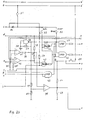
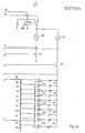
- FIG. 2 which shows the overall circuit of the device according to the invention, has been divided into three parts for the sake of clarity, the associated connection points being identified with lowercase letters a-r.
- the charging logic is also connected to terminal U6V2 via the voltage divider 18, 19 and the relay 28 drops out, so that the lamp 29 and the emergency lamp connected in parallel are supplied with voltage 30, which has a lower power consumption than the lamp 29 takes place via the battery.
- the relay 28 is energized and the lamps 29,30 are supplied via the terminal U6V2 (Fig.2c) (ie the luminous flux is taken from the external voltage supply and not from the battery).
- a voltage stabilization circuit consisting of a zener diode 36 and a capacitor 37 is connected to the switch 31 via a diode 34 and a resistor 35.
- a voltage divider 38, 39 is connected to this, to which the reference input of a comparator 40 is connected, the second input of which is connected to the terminal B / 2 +, the reference voltage determined by the voltage divider 38, 39 being selected such that the output of the comparator 40 is switched through to ground when the battery 1 is already largely discharged.
- the transistor 41 the base of which is connected to the output of the comparator 40, leads to a parallel connection of the resistor 42 to the resistor 38, as a result of which the comparator is connected.
- applied reference voltage increases and thereby a swinging of the comparator between its two initial states is avoided in the event of a discharge of the battery, which is connected to the switching of the comparator 40 to ground.
- the output signal of the comparator 40 which is a "HIGH” signal when the battery 1 is sufficiently charged, is sent to the logic consisting of the gates 43, 44, 45, 46, 47, namely to the NAND gate 43, whose second input is via the voltage divider 48, 49 is connected to the diode 34 and is therefore supplied with a "HIGH” signal when the switch 31 is closed.
- the AND gate 46 controlling the transistor 48 assigned to the emergency lamp 30 is blocked as long as the switch 32 is open and the comparator 40 supplies a "HIGH” signal.
- the output of the comparator 40 switches to "LOW", as a result of which the AND gate 46 is released via the NAND gate 43 and the emergency lamp is switched on via the transistor 48. At the same time, the AND gate 47 is blocked via the NAND gate 44, which in turn blocks the transistor 49 and thus the main lamp is switched off. This ensures that the battery is less stressed and there is still light for the way back to the charging point (approx. 1 hour).
- the output of the comparator 50 (FIG. 2a), which is provided to protect against excessive discharge of the battery, and which, like the comparator 40 with its reference input, is connected to a voltage divider connected to the voltage stabilizing circuit 36, 37 and is connected to terminal B / 2 + with its second input, is not connected to ground.
- This switching occurs when the battery is dangerously discharged.
- a parallel connection of a resistor 53 via a transistor 54 to the resistor 51 of the voltage divider 51, 52 is provided to achieve a corresponding switching hysteresis when the output of the comparator 50 switches through to ground.
- the AND gate 45 the second input of which is supplied with a "HIGH” signal via the NAND gate 55 if there is no mains supply and therefore the terminal U6V2 is dead, or if the mains supply is present, the switch S1 is in position "ON” is brought, no "HIGH” signal from the AND gates 46,47, so that they cannot switch through the assigned transistors 48,49 and therefore the lamps 29,30 cannot be put into operation. This will make him It is sufficient that the entire load is switched by the battery when the battery is empty, thereby preventing the battery from over-discharging.
- the AND gate 45 emits a "HIGH” signal to the gates 46 and 47 and prepares them for switching through ensured while charging the battery. If the switch S1 is in the "OFF" position, the output of the NAND gate 55 is dependent on the voltage U6V2. If one of the external power supplies is excluded, the output of the NAND gate 55 supplies a "LOW” signal and thus blocks the AND gates 46, 47 via the AND gate 45, which means that the lamps 29, 30 are kept off. Only when the external voltage source fails does the NAND gate 55 switch to "HIGH” and the function set via switches 31, 32 and 33 is released. This causes e.g. in the event of a power failure, the light supply is taken over by the hand lamp.
- the one inputs of the two AND gates 46, 47 are connected to the switch 33, with which a permanent signal can be applied in the "permanent" position, and to an oscillator circuit, which is provided by the NAND gate 56, which has a larger switching hysteresis and the resistance 57 and the capacitor 58 is connected.
- the oscillator signal is immediately available when switches 31 or T61 are actuated.
- the capacitor is discharged when it is switched on.
- the output of the NAND gate 56 is thus "HIGH” and begins to charge the capacitor 58 via the resistor 57. If the toggle threshold "on” of gate 56 is reached, the output of this gate switches to "LOW” and capacitor 58 is discharged again via resistor 57.
- the output of gate 56 tilts back to "HIG” etc.
- the frequency is proportional to the product of the resistance value of the capacitor capacitance. If switch 33 is open, the oscillator signal is present at the inputs of AND gates 46 , 47 at. Depending on which of the two AND gates is enabled, the oscillator signal is fed to the transistor 48 or 49, which to the lamp concerned flashes.
- a button 61 is connected to the battery 1 or the terminal B +. Via this button 61, one of the electrodes of a number of light-emitting diodes 62 connected in parallel, the other electrodes with the output of an associated comparator 63 are connected to terminal B +.
- a push-button 61 can also be used to connect a voltage divider 64, 65 to terminal B +, the center tap of which is connected to one of the inputs of the comparators 63 which are connected to one another.
- the reference inputs + of the comparators 63 are on taps of a series. circuit of resistors 66 to 76 laid, which are expediently designed according to the characteristic curve of the battery 1 such that the number of luminous light-emitting diodes 62 corresponds to the number of operating hours remaining of the lamp 29 until the battery is next charged, the comparators 63 on their Then switch outputs to ground when the voltage at their reference inputs + is more negative than the voltage at their other inputs. Thread break detectors are connected between the lamps 29, 30 and their associated transistors, which are essentially formed by the comparators 77, 78.
- the reference inputs (-) of these comparators 77, 78 can be connected to terminal B + via voltage divider 79, 80 (Fig. 2a) and switch 31, or can be connected to the battery, this voltage divider being dimensioned such that the potential at the reference inputs is only relatively little above the ground potential, but is below UcEsat.
- the other inputs of these comparators 78, 77 are connected to lamp 29 and a resistor 89 connected to ground, or to lamp 30 and a resistor 90 connected to ground.
- the comparator 77 which monitors the emergency lamp 30, operates in the same way as the comparator 78, but its output affects only the voltage divider 49, 92, which also causes the LEDs 62 to flash in the manner described above if the filament of this lamp breaks is and therefore the output of the comparator 77 switches through to ground.
- the input of the NAND gate 43 connected to the comparator 40 is held at "HIGH" potential via the resistor 93, which can be connected to the battery via the switch 31, as long as the output of the comparator 40 has not switched through to ground.
- the same also applies with respect Lich the AND gate 45, the input connected to the comparator 50 via the resistor 94, which can be connected via the switch 31 to the battery 1, or the terminal B +, is kept at high potential as long as the output of the comparator is not 50 switches through to ground when the battery is already exhausted.
- those can also be used for the comparators 40, 50 which only switch through against a potential or, in their other switching state, the potential adjusts itself at its output after the external wiring.
- the NAND gate 55 can be connected with its one input to the battery via a resistor 94 and the switch 31 and can also be connected to ground via the switch SI.
- the second input of this gate 55 is connected to the terminal U6V2 via the voltage divider 95.96.
- the NAND gate 55 emits a "LOW" signal when the switch SI is in its OFF position, by means of which the AND gate 45 is blocked, whereby the AND gates 46 and 47 and thus the transistors 48 and 49 are blocked. If the mains supply fails or the switch S1 is brought into its ON position, the NAND gate 55 emits a "HIGH" signal, by means of which the AND gate 45 is enabled. This makes it possible to put the lamps 29 or 30 into operation even when the mains supply is present, and the battery can be charged at the same time.
Landscapes
- Engineering & Computer Science (AREA)
- Power Engineering (AREA)
- Physics & Mathematics (AREA)
- General Physics & Mathematics (AREA)
- Burglar Alarm Systems (AREA)
- Telephone Function (AREA)
- Circuit Arrangement For Electric Light Sources In General (AREA)
- Telephone Set Structure (AREA)
- Secondary Cells (AREA)
- Battery Mounting, Suspending (AREA)
- Primary Cells (AREA)
Applications Claiming Priority (2)
| Application Number | Priority Date | Filing Date | Title |
|---|---|---|---|
| AT1932/85 | 1985-06-28 | ||
| AT0193285A AT383914B (de) | 1985-06-28 | 1985-06-28 | Geraet mit einer aufladbaren batterie |
Publications (3)
| Publication Number | Publication Date |
|---|---|
| EP0207054A2 true EP0207054A2 (fr) | 1986-12-30 |
| EP0207054A3 EP0207054A3 (en) | 1988-08-24 |
| EP0207054B1 EP0207054B1 (fr) | 1992-07-29 |
Family
ID=3524136
Family Applications (1)
| Application Number | Title | Priority Date | Filing Date |
|---|---|---|---|
| EP86890141A Expired - Lifetime EP0207054B1 (fr) | 1985-06-28 | 1986-05-14 | Appareil pourvu d'une batterie rechargeable |
Country Status (3)
| Country | Link |
|---|---|
| EP (1) | EP0207054B1 (fr) |
| AT (2) | AT383914B (fr) |
| DE (1) | DE3686211D1 (fr) |
Cited By (7)
| Publication number | Priority date | Publication date | Assignee | Title |
|---|---|---|---|---|
| FR2624280A1 (fr) * | 1987-12-08 | 1989-06-09 | Codexim | Systeme de securite de regulation de chauffage d'un volume par fluide gazeux caloporteur |
| EP0343056A1 (fr) * | 1988-05-16 | 1989-11-23 | Aglo S.A. | Chargeur automatique pour batteries ou accumulateurs |
| FR2636478A1 (fr) * | 1988-09-13 | 1990-03-16 | Luminox | Dispositif de controle et de charge d'une batterie d'accumulateurs notamment |
| WO1990009598A1 (fr) * | 1989-02-11 | 1990-08-23 | Sandor Nagy | Dispositif de controle et d'indication d'une reserve d'energie minimum determinee dans les batteries |
| EP0568800A1 (fr) * | 1992-04-03 | 1993-11-10 | Ivoclar Ag | Dispositif rechargeable pour le durcissement par la lumière |
| EP0636897A1 (fr) * | 1993-07-29 | 1995-02-01 | Canon Kabushiki Kaisha | Dispositif et méthode de contrôle d'énergie |
| US7496460B2 (en) | 2006-09-06 | 2009-02-24 | Eastway Fair Company Limited | Energy source monitoring and control system for power tools |
Family Cites Families (6)
| Publication number | Priority date | Publication date | Assignee | Title |
|---|---|---|---|---|
| DE2742675A1 (de) * | 1977-09-22 | 1979-04-05 | Bosch Gmbh Robert | Schaltungsanordnung zur ladezustandsanzeige einer akkumulatorbatterie |
| DE3001897A1 (de) * | 1980-01-19 | 1981-07-23 | Kodak Ag, 7000 Stuttgart | Batteriepruefeinrichtung |
| DE3023573A1 (de) * | 1980-06-24 | 1982-01-14 | Hermann Mellert GmbH & Co KG Fabrik für Feinmechanik und Elektrotechnik, 7518 Bretten | Schaltungsanordnung zur kontrolle des ladezustands von batterie- oder akkubetriebenen geraeten |
| GB2081531A (en) * | 1980-07-26 | 1982-02-17 | Lucas Industries Ltd | Hand lamp |
| CH642808B (fr) * | 1981-01-05 | 1900-01-01 | Rolex Montres | Procede pour determiner l'etat de decharge d'une pile electrique et dispositif pour la mise en oeuvre de ce procede. |
| US4560937A (en) * | 1981-11-16 | 1985-12-24 | Curtis Instruments, Inc. | Battery state of charge metering method and apparatus |
-
1985
- 1985-06-28 AT AT0193285A patent/AT383914B/de not_active IP Right Cessation
-
1986
- 1986-05-14 EP EP86890141A patent/EP0207054B1/fr not_active Expired - Lifetime
- 1986-05-14 DE DE8686890141T patent/DE3686211D1/de not_active Expired - Lifetime
- 1986-05-14 AT AT86890141T patent/ATE78960T1/de not_active IP Right Cessation
Cited By (10)
| Publication number | Priority date | Publication date | Assignee | Title |
|---|---|---|---|---|
| FR2624280A1 (fr) * | 1987-12-08 | 1989-06-09 | Codexim | Systeme de securite de regulation de chauffage d'un volume par fluide gazeux caloporteur |
| EP0343056A1 (fr) * | 1988-05-16 | 1989-11-23 | Aglo S.A. | Chargeur automatique pour batteries ou accumulateurs |
| FR2636478A1 (fr) * | 1988-09-13 | 1990-03-16 | Luminox | Dispositif de controle et de charge d'une batterie d'accumulateurs notamment |
| EP0364371A1 (fr) * | 1988-09-13 | 1990-04-18 | Luminox S.A. | Dispositif de contrôle et de charge d'une batterie d'accumulateurs notamment |
| WO1990009598A1 (fr) * | 1989-02-11 | 1990-08-23 | Sandor Nagy | Dispositif de controle et d'indication d'une reserve d'energie minimum determinee dans les batteries |
| EP0568800A1 (fr) * | 1992-04-03 | 1993-11-10 | Ivoclar Ag | Dispositif rechargeable pour le durcissement par la lumière |
| EP0636897A1 (fr) * | 1993-07-29 | 1995-02-01 | Canon Kabushiki Kaisha | Dispositif et méthode de contrôle d'énergie |
| US5600228A (en) * | 1993-07-29 | 1997-02-04 | Canon Kabushiki Kaisha | Power managing apparatus and method |
| US7496460B2 (en) | 2006-09-06 | 2009-02-24 | Eastway Fair Company Limited | Energy source monitoring and control system for power tools |
| US7580803B2 (en) | 2006-09-06 | 2009-08-25 | Techtronic Power Tools Technology Limited | Energy source monitoring and control system |
Also Published As
| Publication number | Publication date |
|---|---|
| EP0207054A3 (en) | 1988-08-24 |
| DE3686211D1 (de) | 1992-09-03 |
| EP0207054B1 (fr) | 1992-07-29 |
| ATA193285A (de) | 1987-01-15 |
| ATE78960T1 (de) | 1992-08-15 |
| AT383914B (de) | 1987-09-10 |
Similar Documents
| Publication | Publication Date | Title |
|---|---|---|
| DE69131713T2 (de) | Unterbrechungsfreies, geschütztes beleuchtungssystem | |
| DE3844093C2 (fr) | ||
| DE3926655C2 (de) | Schaltungsanordnung zum Wiederaufladen von Batterien | |
| DE2657167A1 (de) | Schaltung zum selbsttaetigen umschalten einer last von einer primaerstromquelle an eine sekundaerstromquelle | |
| DE69406860T2 (de) | Batterieladesystem mit Vorrichtung zur Bestimmung des Batterietyps und der Polarität | |
| EP0240883A2 (fr) | Procédé d'obtention d'une protection de décharge profonde pour une batterie rechargeable et circuit pour la réalisation du procédé | |
| DE2724278A1 (de) | Notstromversorgungseinrichtung | |
| CH626196A5 (fr) | ||
| EP1233657B1 (fr) | Circuit de protection pour tube fluorescent | |
| EP0115625B1 (fr) | Procédé et dispositif pour indiquer optiquement et/ou acoustiquement l'état de charge d'une batterie ou d'un accumulateur | |
| EP0460585A2 (fr) | Installation d'éclairage avec dynamo pour bicyclette | |
| DE3415573C2 (fr) | ||
| EP0207054B1 (fr) | Appareil pourvu d'une batterie rechargeable | |
| DE1588540A1 (de) | Transistorgesteuertes Batterieladegeraet | |
| DE3322943C2 (fr) | ||
| EP0399201B1 (fr) | Système d'alarme pour lumière de flash | |
| DE1438857B2 (de) | Gerät zum Laden von Akkumulatoren | |
| DE2547495A1 (de) | Warnsystem | |
| DE102012220760A1 (de) | Multifunktionales Betriebsgerät zum Versorgen eines Verbrauchers wie eines LED-Moduls sowie Verfahren zu dessen Betrieb | |
| EP0617499A1 (fr) | Circuit d'alimentation en courant | |
| DE3532229A1 (de) | Elektronischer sicherheitstemperaturbegrenzer | |
| DE19532677B4 (de) | Überwachungsschaltung für wenigstens eine Versorgungsspannung | |
| EP0635171B1 (fr) | Bloc electronique d'alimentation a decoupage | |
| DE60021390T2 (de) | Notlichteinheit, verwendbar mit verschiedenen Typen von Batterien | |
| DE3138512C2 (fr) |
Legal Events
| Date | Code | Title | Description |
|---|---|---|---|
| PUAI | Public reference made under article 153(3) epc to a published international application that has entered the european phase |
Free format text: ORIGINAL CODE: 0009012 |
|
| AK | Designated contracting states |
Kind code of ref document: A2 Designated state(s): AT BE CH DE FR GB IT LI LU NL SE |
|
| PUAL | Search report despatched |
Free format text: ORIGINAL CODE: 0009013 |
|
| AK | Designated contracting states |
Kind code of ref document: A3 Designated state(s): AT BE CH DE FR GB IT LI LU NL SE |
|
| 17P | Request for examination filed |
Effective date: 19890127 |
|
| 17Q | First examination report despatched |
Effective date: 19900827 |
|
| GRAA | (expected) grant |
Free format text: ORIGINAL CODE: 0009210 |
|
| AK | Designated contracting states |
Kind code of ref document: B1 Designated state(s): AT BE CH DE FR GB IT LI LU NL SE |
|
| PG25 | Lapsed in a contracting state [announced via postgrant information from national office to epo] |
Ref country code: FR Effective date: 19920729 Ref country code: IT Free format text: LAPSE BECAUSE OF FAILURE TO SUBMIT A TRANSLATION OF THE DESCRIPTION OR TO PAY THE FEE WITHIN THE PRE;WARNING: LAPSES OF ITALIAN PATENTS WITH EFFECTIVE DATE BEFORE 2007 MAY HAVE OCCURRED AT ANY TIME BEFORE 2007. THE CORRECT EFFECTIVE DATE MAY BE DIFFERENT FROM THE ONE RECORDED.SCRIBED TIME-LIMIT Effective date: 19920729 Ref country code: GB Effective date: 19920729 Ref country code: NL Effective date: 19920729 Ref country code: SE Effective date: 19920729 Ref country code: BE Effective date: 19920729 |
|
| REF | Corresponds to: |
Ref document number: 78960 Country of ref document: AT Date of ref document: 19920815 Kind code of ref document: T |
|
| REF | Corresponds to: |
Ref document number: 3686211 Country of ref document: DE Date of ref document: 19920903 |
|
| EN | Fr: translation not filed | ||
| NLV1 | Nl: lapsed or annulled due to failure to fulfill the requirements of art. 29p and 29m of the patents act | ||
| GBV | Gb: ep patent (uk) treated as always having been void in accordance with gb section 77(7)/1977 [no translation filed] |
Effective date: 19920729 |
|
| PLBI | Opposition filed |
Free format text: ORIGINAL CODE: 0009260 |
|
| PG25 | Lapsed in a contracting state [announced via postgrant information from national office to epo] |
Ref country code: LU Free format text: LAPSE BECAUSE OF NON-PAYMENT OF DUE FEES Effective date: 19930531 |
|
| 26 | Opposition filed |
Opponent name: BRAUN AG, FRANKFURT Effective date: 19930429 |
|
| PLAB | Opposition data, opponent's data or that of the opponent's representative modified |
Free format text: ORIGINAL CODE: 0009299OPPO |
|
| R26 | Opposition filed (corrected) |
Opponent name: BRAUN AG PATENTABTEILUNG Effective date: 19930429 |
|
| PLBN | Opposition rejected |
Free format text: ORIGINAL CODE: 0009273 |
|
| STAA | Information on the status of an ep patent application or granted ep patent |
Free format text: STATUS: OPPOSITION REJECTED |
|
| 27O | Opposition rejected |
Effective date: 19950316 |
|
| PGFP | Annual fee paid to national office [announced via postgrant information from national office to epo] |
Ref country code: AT Payment date: 19960531 Year of fee payment: 11 |
|
| PGFP | Annual fee paid to national office [announced via postgrant information from national office to epo] |
Ref country code: DE Payment date: 19960724 Year of fee payment: 11 |
|
| PGFP | Annual fee paid to national office [announced via postgrant information from national office to epo] |
Ref country code: CH Payment date: 19960725 Year of fee payment: 11 |
|
| PG25 | Lapsed in a contracting state [announced via postgrant information from national office to epo] |
Ref country code: AT Effective date: 19970514 |
|
| PG25 | Lapsed in a contracting state [announced via postgrant information from national office to epo] |
Ref country code: CH Free format text: LAPSE BECAUSE OF NON-PAYMENT OF DUE FEES Effective date: 19970531 Ref country code: LI Free format text: LAPSE BECAUSE OF NON-PAYMENT OF DUE FEES Effective date: 19970531 |
|
| REG | Reference to a national code |
Ref country code: CH Ref legal event code: PL |
|
| PG25 | Lapsed in a contracting state [announced via postgrant information from national office to epo] |
Ref country code: DE Free format text: LAPSE BECAUSE OF NON-PAYMENT OF DUE FEES Effective date: 19980203 |