EP0460585A2 - Installation d'éclairage avec dynamo pour bicyclette - Google Patents
Installation d'éclairage avec dynamo pour bicyclette Download PDFInfo
- Publication number
- EP0460585A2 EP0460585A2 EP91109065A EP91109065A EP0460585A2 EP 0460585 A2 EP0460585 A2 EP 0460585A2 EP 91109065 A EP91109065 A EP 91109065A EP 91109065 A EP91109065 A EP 91109065A EP 0460585 A2 EP0460585 A2 EP 0460585A2
- Authority
- EP
- European Patent Office
- Prior art keywords
- dynamo
- voltage
- light
- lamp
- bicycle
- Prior art date
- Legal status (The legal status is an assumption and is not a legal conclusion. Google has not performed a legal analysis and makes no representation as to the accuracy of the status listed.)
- Granted
Links
Images



Classifications
-
- B—PERFORMING OPERATIONS; TRANSPORTING
- B62—LAND VEHICLES FOR TRAVELLING OTHERWISE THAN ON RAILS
- B62J—CYCLE SADDLES OR SEATS; AUXILIARY DEVICES OR ACCESSORIES SPECIALLY ADAPTED TO CYCLES AND NOT OTHERWISE PROVIDED FOR, e.g. ARTICLE CARRIERS OR CYCLE PROTECTORS
- B62J6/00—Arrangement of optical signalling or lighting devices on cycles; Mounting or supporting thereof; Circuits therefor
- B62J6/01—Electric circuits
- B62J6/015—Electric circuits using electrical power not supplied by the cycle motor generator, e.g. using batteries or piezo elements
Definitions
- the invention relates to a bicycle light system with a circuit that has at least one front light, a rear light, a dynamo that can be driven by the bicycle, and a voltage limiting circuit for the light voltage.
- the excess power is not destroyed, but is either not drawn from the dynamo at all or used to charge batteries if necessary. Accordingly, not only the voltage, but also the rotational resistance of the dynamo is stabilized at an optimal value.
- the dynamo output voltage is measured by means of a threshold switch and converted into at least two, preferably three, switching states of the system, which are optimally adapted to the voltage generated in each case.
- the dynamo can be designed as a continuously running hub dynamo. The power thus generated is sufficient for optimal use for both driving and parking light operation.
- the claimed bicycle light system can be in different configurations, ie with one or two lamps for the front light, with or without rechargeable Batteries and with or without control logic can be provided, which can be combined with conventional dynamos and lights, depending on the configuration.
- the control logic switches a charger for the rechargeable batteries into different charging cycles, depending on the current driving and operating status of the bike. This means that both the charging process and the operating status of the lights can be optimally adapted to the driving status, so that with normal, cyclical driving behavior, both driving lights and parking lights are always guaranteed in accordance with legal standards.
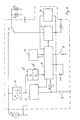
- FIGS. 1 to 3 The mode of operation of a basic circuit of the lighting system will first be explained with reference to FIGS. 1 to 3.
- This basic circuit also represents a first stage of expansion of the system.
- the lighting system has a generator G, which is designed as a bicycle dynamo, as will be explained in more detail. After appropriate rectification, this delivers a direct voltage U E or a direct current, the size of which increases with the driving speed.
- the output voltage U E can additionally be smoothed by means of a capacitor K at the output and the electronics can be protected against overvoltage with a zener diode.
- the voltage-speed characteristic curve K of the dynamo used (see FIG. 6) has the effect that, at higher driving speeds, overvoltages are generated which would destroy the bicycle lamps and which do not meet the legal standards.
- a switching regulator 1 is arranged between the dynamo G and the lamps R L (rear light) and V L1 , or V L2 (front light), which can be switched on and off via a switch 2. If it is switched off, the switching regulator 1 acts like an open switch and the lamps are not connected to the Dynamo G. If it is switched on, in this way it stabilizes the voltage at a selectable value with almost no loss.
- An electronic switch 3 is continuously closed up to a desired output voltage U A (in the present example 5.8 V).
- the dynamo voltage can increase without loss in this area until the desired output voltage U A is reached. If the dynamo voltage continues to increase (FIG. 3), the electronic switch is opened and closed again by an oscillator 11 at a fixed switching frequency of, for example, 100 kHz.
- the pulse duty factor te / T is changed as a function of the input voltage U E in such a way that the mean value of the transmitted voltage pulses corresponds precisely to the stabilized output voltage U A. At the same time, this also involves a current limitation.
- the voltage pulses are converted to DC voltage U A in an LC filter.
- a corresponding control circuit for setting the duty cycle with an operational amplifier 4 and a reference voltage source 5 is shown in FIG. 2.
- the control amplifier is preferably constructed using C-MOS technology and works with an efficiency of over 90%.
- the dynamo voltage U E exceeds the desired output voltage U A , electrical power is not destroyed, but the dynamo is relieved, which also limits the electromotive force in the dynamo and thus the driving resistance to an optimal value. If the Dynamo G works in this area, the lamps of the front and rear lights shine with constant brightness. The lamp ratings are matched to this stabilized voltage with, for example, 6 V / 2.5 W for the front light and 6 V / 0.6 W for the rear light.
- a threshold value switch 6 is also provided in a second expansion stage of the system described (cf. FIG. 1 or 4), which taps off the dynamo voltage.
- the threshold switch 6 generates two states and the front light has two lamps (or a lamp with two filaments) with different nominal voltages.
- the switching regulator has two stabilization levels corresponding to these nominal voltages.
- the lamps are operated with fluctuating dynamo voltage but relatively good luminous efficacy.
- FIGS. 4 and 8 A further application of the circuit principle is shown in FIGS. 4 and 8, the switching states adapted to the dynamo voltage now being generated not on the lamp side but on the supply or charge control side and used for voltage stabilization or optimal battery charging.
- rechargeable batteries 8 (with a nominal voltage of 3.6 V) are provided on the supply side, which are connected to the dynamo G via a battery charging converter 9, which is shown in detail in FIG.
- the dynamo G has a voltage-speed characteristic curve K (FIGS. 6, 7).
- a front light V L with only one lamp and a rear light R L are provided on the consumer side, so that this system can be operated with conventional bicycle lights.
- three operating states are distinguished when the light is switched on, which are referred to below with the letters A, B and C. 6 shows these operating states as a function of the driving speed of the bicycle.
- the first line in FIG. 6 shows the voltage-speed characteristic curve K of Dynamo G.
- the second line shows the changeover from operating state A to operating state B in accordance with the logic signal from a first Threshold switch 6 I.
- the third line represents the corresponding logic signal of a second threshold switch 6 II .
- the bottom line shows the charging current I for the battery 8.
- the course of the output voltage U A occurring on the lamps can be seen in FIG.
- Operating state A is at standstill or slow driving speed (up to e.g. 7 km / h) as long as the output voltage of dynamo G is below a first threshold value I of e.g. 3.6 V remains.
- the lamp energy is drawn from the battery 8, and the dynamo energy is charged into the battery 8 after a suitable DC / DC conversion in the charging converter 9.
- the charging converter 9 works as a constant low-current converter for generating a constant charging current of approximately 10 mA for the battery 8. This load corresponds approximately to the normal lamp resistance tolerances and is therefore permissible. For the battery 8, however, it is important that it is also charged at the (most frequent) driving speed between approximately 6 and 14 km / h.
- the dynamo voltage U E exceeds the lamp nominal voltage of 6 V.
- the operating state C is assumed as soon as a threshold value II of approx. 5.8 V of the dynamo voltage is reached.
- the electronics act as a voltage stabilizer, because if the nominal lamp voltage is exceeded, their lifespan is reduced considerably.
- the excess dynamo energy is loaded into the battery 8.
- the charging current that can be achieved in this way can reach up to 250 mA (rapid charging).
- FIG. 4 A corresponding circuit structure is shown in FIG.
- the standardized Dynamo G is connected to the electronics via a rectifier 30 with sieving.
- the threshold value switch 6 is graphically corresponding divided into two blocks.
- the threshold switch 6 determines the threshold values of the dynamo voltage and sends corresponding control signals to a control logic 10.
- the control logic 10 has three control loops 31, each of which is assigned to one of the operating conditions mentioned, and which is therefore shown in FIG. 5 by corresponding blocks A, B, C are shown. Depending on the operating state, one of these control loops is connected to the charge converter 9 via a logic 32 and supplies the latter with corresponding control signals, as can be seen from FIG.
- the charging converter is connected between the rectifier 30 and the battery 8 and also has a switching regulator 33 which receives the control signals of the control circuits 31 via a feedback input F B.
- the correspondingly regulated output signal of this switching regulator arrives via a transformer 34 and a rectifier arrangement (see FIGS. 1 to 3) as direct current in the battery 8, as can be seen in particular from FIG. 5.
- the load In operating state A, the load is regulated by adjusting the resistance in such a way that the dynamo energy generated in this area is optimally charged into the battery 8.
- the lamp draws its energy entirely from the battery, which is why the lamp voltage does not fall below the battery voltage of 3.6 V.
- the control circuit 31 A works in such a way that when the first threshold value voltage I is reached, the dynamic load corresponds approximately to the lamp load (of approximately 12 ⁇ ). This is to keep the changeover hysteresis ⁇ U small when switching over to the operating state B, so that no strong light fluctuation occurs in the lamps V L and R L.
- the lamp draws the current from the dynamo (FIG. 7). Until the full lamp voltage is reached, it should not be excessively stressed by the battery charging. Nevertheless, it is important for the energy balance that a charge is also made in this frequent driving area.
- the switching regulator 33 is therefore regulated via the control circuit B in such a way that a small constant charging current of e.g. 10 mA is generated. Since this only corresponds approximately to the normal lamp resistance tolerances, the luminous efficacy is not noticeably impaired by this.
- the threshold switch 6 II switches the control circuit 31 C to the charging converter 9.
- This control circuit regulates the dynamic load so that a voltage of 6 V is achieved by means of a controller load definitely not exceeded.
- the overvoltage energy is loaded into the battery (see FIGS. 6 and 8).
- a charging current of up to 250 mA can be generated and the battery can be charged quickly.
- a switching regulator 1 ' is arranged between the battery 8 and the lamps. It stabilizes the voltage or the current from the battery 8 or from the charging converter 9, which reaches the lamps, on one Value of 3.2 V, for example, so that a constant lamp brightness that promotes safety is guaranteed. It becomes active in operating state A with a low dynamo voltage.
- the LED display enables the driver to recognize the status of the lighting system in every operating phase.
- the display is as follows: The diode lights continuously when the light is on and the battery capacity between about 30% and 90%.
- the diode flashes every 1 Hz when the battery capacity drops below around 30% when driving with lights on.
- the diode flashes every 4 Hz when the light is off and the batteries are charged until a battery capacity of around 90% is reached.
- the LED display becomes inactive.
- the battery monitoring circuit 36 also has the function of a battery presence control. If the battery 8 is not present or is deeply discharged, this is determined via a presence control logic and stored in the control logic 10. In this case, the electronics described remain inactive. The lamps V L , R L are then connected directly to the dynamo G via a relay R 1, R 1 (FIG. 4). In this case, the battery charge converter works in operating mode B, ie it generates one small charging current. On the one hand, deep discharge protection for the battery 8 and, on the other hand, ensuring driving with light is achieved.
- the control logic can be operated using key 2.
- the memory in the control logic 10 can be set to "on” with a longer push button actuation (greater than e.g. 0.25 sec), whereby the lighting system is switched on via the control logic 10. With a short button confirmation (less than 0.25 sec), the memory is set to "Off” and the system is switched off.
- a parking light timer 13 is connected to the control logic 10, the function of which will be explained below.
- One advantage of the described version with battery support lies in the generation of parking lights. If the bicycle is stopped and the output voltage of the dynamo G drops to zero, then, as described above, the operating state with battery supply occurs with the voltage stabilized at 3.2 V. The light continues to burn with reduced consumption if it is switched on. If the dynamo voltage falls below a minimum value Vo (of, for example, 1 V), this is determined in the threshold switch 6 and a signal for the control logic 10 is generated. This is connected to a timer circuit 13, which starts at this moment and counts during a certain time T (of, for example, 4 minutes). During this time, the switching regulator 1 'remains switched on and the light continues to burn.
- Vo of, for example, 1 V
- the bicycle light system is designed in such a way that both the consumer side and the feed side are switched between different operating states during the entire driving cycle, each of which is optimally adapted to the respective operating situation. This ensures that good light is always available during normal driving cycles, the batteries are always charged and the driving resistance remains limited.
- each switching regulator 1 or 1 being connected to its own lamp (or filament) V L1 or V L2 of the front light.
- Halogen lamps with two filaments of different nominal power are advantageously used for the front light.
- a switch 16 is also provided for the rear light R L , which connects the respectively active switching regulator to the rear light.
- a brake light function is also indicated, which can be added to the rear light R L.
- a brake contact 17 is provided in the area of the brakes and, on the other hand, an LED rear light 18 with two segments (see FIG. 11). One segment serves as a rear light at night and the other as a brake light.
- Both are fed via the same wire, the transmission of the brake light being modulated by means of additional electronics 19 and decoded in the brake light. This allows the taillight and / or the brake light to be actuated via the same supply. Compatibility with normal rear lights is guaranteed.
- FIG. 10 shows, as a further option, a control circuit 20 for a display and actuation unit 21, which is connected to the control logic 10.
- the driving speed can be inferred from the measured dynamo voltage U E , from which the distance traveled, etc. can be calculated and displayed by measuring the time.
- the bicycle lighting system described so far can be operated with conventional Dynamos G.
- the bicycle lighting system described is composed of several components which, depending on the configuration of the system, can be partially replaced by conventional components.
- 11 shows the system with its components in an overview.
- Figures 12 and 13 show appropriately equipped bicycles.
- the centerpiece of the system is an electronics housing 22 which contains the electronics described in the possible expansion stages.
- the electronics housing 22 preferably also serves as a lamp housing for the front light if it is equipped with two halogen lamps V L1 , V L2 (or a lamp with two filaments).
- the electronics with a conventional front light V L 'operated, a cover 23 can be arranged on the housing 22 instead of the light part. This is then attached to the bicycle frame at a suitable point (Fig. 13).
- a separate display unit 21 is provided, which is arranged in the driver's field of vision (FIG. 12) and has the described LED displays and switches 11.
- the rechargeable batteries 8 are usually accommodated in the electronics housing 22. If an additional battery 8 'or sun cells 24 are used, these can be arranged in the region of the luggage rack (FIG. 12).
- the electronics are connected to a Dynamo G, which can be a wheel hub dynamo, for example. If an LED rear light R L with brake light B L is used, the brake is accordingly equipped with a button 17 for the brake light, which is connected to electronics 22 as described. However, a conventional rear light R L 'can also be used.
- FIG. 12 shows a bicycle which is provided with a fully developed bicycle light system with hub dynamo 32, electronics 22 with attached halogen lamps V L1 , V L2 , display unit 21, LED rear light R L with brake light B L and sun cells 24.
- the electronics correspond to those of FIG. 6.
- FIG. 13 shows the bicycle light system in combination with conventional front light V L ', conventional dynamos G and conventional rear light R L.
- the electronics correspond to those of FIG. 4.
- the bicycle light system allows economical, optimal use of the available electrical power, which ensures correct, optimal light generation in all cycle cycles of the bicycle. It can be integrated into existing bicycle lighting systems in various stages.
Landscapes
- Engineering & Computer Science (AREA)
- Mechanical Engineering (AREA)
- Lighting Device Outwards From Vehicle And Optical Signal (AREA)
Applications Claiming Priority (3)
| Application Number | Priority Date | Filing Date | Title |
|---|---|---|---|
| CH191390 | 1990-06-07 | ||
| CH1913/90 | 1990-06-07 | ||
| SG87894A SG87894G (en) | 1990-06-07 | 1994-06-30 | Bicycle lighting equipment with dynamo |
Publications (3)
| Publication Number | Publication Date |
|---|---|
| EP0460585A2 true EP0460585A2 (fr) | 1991-12-11 |
| EP0460585A3 EP0460585A3 (en) | 1992-03-25 |
| EP0460585B1 EP0460585B1 (fr) | 1993-12-22 |
Family
ID=25688985
Family Applications (1)
| Application Number | Title | Priority Date | Filing Date |
|---|---|---|---|
| EP91109065A Expired - Lifetime EP0460585B1 (fr) | 1990-06-07 | 1991-06-04 | Installation d'éclairage avec dynamo pour bicyclette |
Country Status (7)
| Country | Link |
|---|---|
| US (1) | US5247430A (fr) |
| EP (1) | EP0460585B1 (fr) |
| JP (1) | JPH09150764A (fr) |
| DE (1) | DE59100747D1 (fr) |
| DK (1) | DK0460585T3 (fr) |
| HK (1) | HK70894A (fr) |
| SG (1) | SG87894G (fr) |
Cited By (3)
| Publication number | Priority date | Publication date | Assignee | Title |
|---|---|---|---|---|
| WO1995018739A1 (fr) * | 1994-01-11 | 1995-07-13 | Edwin Schwaller | Systeme d'eclairage pour bicyclettes et generateur |
| FR2727265A1 (fr) * | 1994-11-23 | 1996-05-24 | Soubitez | Regulateur de tension alternative pour alternateur de bicyclette |
| EP1600366A1 (fr) * | 2004-05-26 | 2005-11-30 | Shimano Inc. | Dispositif de protection de lampe de bicyclette |
Families Citing this family (21)
| Publication number | Priority date | Publication date | Assignee | Title |
|---|---|---|---|---|
| JP3396655B2 (ja) * | 2000-02-29 | 2003-04-14 | 株式会社シマノ | 自転車用電源装置 |
| US6502842B2 (en) * | 2001-01-30 | 2003-01-07 | Frank Ko | Bicycle power generating arrangement |
| DE10142358B4 (de) * | 2001-08-30 | 2010-09-02 | Hammerschmidt, Hartwig, Dipl.-Ing. | Funktionskontrolle des Fahrradrücklichtes |
| TWI244448B (en) * | 2002-07-10 | 2005-12-01 | Shimano Kk | Over-voltage prevention device for a bicycle dynamo |
| JP2004048897A (ja) * | 2002-07-11 | 2004-02-12 | Shimano Inc | 自転車用ダイナモの充電装置 |
| JP3727292B2 (ja) * | 2002-08-20 | 2005-12-14 | 株式会社シマノ | 自転車用電装品駆動装置 |
| JP2005104258A (ja) * | 2003-09-30 | 2005-04-21 | Shimano Inc | 自転車用電装品ホルダー |
| JP3845092B2 (ja) * | 2004-01-16 | 2006-11-15 | 株式会社シマノ | 自転車用点灯装置 |
| FR2865994B1 (fr) * | 2004-02-10 | 2007-04-27 | J C Decaux | Bicyclette equipee d'un systeme de controle embarque |
| JP2005349995A (ja) * | 2004-06-11 | 2005-12-22 | Shimano Inc | 自転車用電気機器の保護回路 |
| US7145256B2 (en) * | 2004-10-05 | 2006-12-05 | Alan William Koharcheck | Lighting system for a bicycle |
| EP1743829B1 (fr) * | 2005-07-12 | 2009-09-02 | Shimano Inc. | Dispositif d'éclairage pour bicyclette avec sortie électrique supplémentaire |
| TW200605467A (en) * | 2005-08-30 | 2006-02-01 | Sheng Li Spring Ind Co Ltd | Chargeable lamp capable of having power supply function |
| JP4168061B2 (ja) * | 2006-04-28 | 2008-10-22 | 株式会社シマノ | 自転車用照明システム |
| JP5430844B2 (ja) * | 2007-11-28 | 2014-03-05 | 三洋電機株式会社 | 自転車用照明装置 |
| DE102009033564A1 (de) * | 2009-07-16 | 2011-01-20 | Busch & Müller KG | Vorrichtung und Verfahren zum Bereitstellen einer Ausgangsspannung |
| TWM370884U (en) * | 2009-07-30 | 2009-12-11 | Dah Ken Ind Co Ltd | Control and management device for bicycle micro-power generation and distribution |
| DE102010051724A1 (de) * | 2010-11-19 | 2012-05-24 | Busch & Müller KG | Verfahren zum Betreiben einer Fahrradbeleuchtung sowie Schaltung zum Betrieb einer elektrischen Last, insbesondere eines Fahrradscheinwerfers, an einem Fahrrad |
| US20120249316A1 (en) * | 2011-04-01 | 2012-10-04 | Lite-On Technology Corporation | Bicycle brake light system |
| US8449157B2 (en) | 2011-08-16 | 2013-05-28 | Trek Bicycle Corp. | Lighted bicycle wheel hub assembly |
| TWI641529B (zh) * | 2016-05-30 | 2018-11-21 | 巨大機械工業股份有限公司 | 充電系統與充電方法 |
Family Cites Families (10)
| Publication number | Priority date | Publication date | Assignee | Title |
|---|---|---|---|---|
| CH150507A (de) * | 1931-02-01 | 1931-10-31 | Grieshaber Eugen | Signaleinrichtung an Fahrzeugen, insbesondere Fahrrädern. |
| US3904920A (en) * | 1973-04-12 | 1975-09-09 | Ronald A Griffith | Safety lighting system |
| DE2519837A1 (de) * | 1975-05-03 | 1976-11-11 | Walter Elberskirch | Lichtanlage fuer zweiraeder |
| GB2050088A (en) * | 1979-03-03 | 1980-12-31 | Whittington A W | Cycle lighting system |
| DK144397C (da) * | 1979-10-31 | 1982-08-02 | P P Dunch | Kredsloeb til automatisk afladebeskyttelse af en passiv stroemkilde |
| EP0040204A1 (fr) * | 1979-11-06 | 1981-11-25 | MURPHY, Thomas | Unite d'amelioration d'un generateur electrique de bicyclette ou autre vehicule |
| EP0141455B1 (fr) * | 1983-09-27 | 1988-05-25 | EKOLIGHT P.v.b.A. | Boîtier de lampe |
| GB8412897D0 (en) * | 1984-05-21 | 1984-06-27 | Mackinnon J M | Electrical power supply device |
| JPS63502652A (ja) * | 1986-03-13 | 1988-10-06 | バウエンス・フランク | 車両用照明装置 |
| GB2215142A (en) * | 1988-02-16 | 1989-09-13 | David Allen | Dynamo lighting system for a bicycle |
-
1991
- 1991-06-04 EP EP91109065A patent/EP0460585B1/fr not_active Expired - Lifetime
- 1991-06-04 DK DK91109065.2T patent/DK0460585T3/da not_active Application Discontinuation
- 1991-06-04 DE DE91109065T patent/DE59100747D1/de not_active Expired - Fee Related
- 1991-06-05 US US07/710,677 patent/US5247430A/en not_active Expired - Fee Related
- 1991-06-06 JP JP3135181A patent/JPH09150764A/ja not_active Withdrawn
-
1994
- 1994-06-30 SG SG87894A patent/SG87894G/en unknown
- 1994-07-21 HK HK70894A patent/HK70894A/xx not_active IP Right Cessation
Cited By (4)
| Publication number | Priority date | Publication date | Assignee | Title |
|---|---|---|---|---|
| WO1995018739A1 (fr) * | 1994-01-11 | 1995-07-13 | Edwin Schwaller | Systeme d'eclairage pour bicyclettes et generateur |
| US5857762A (en) * | 1994-01-11 | 1999-01-12 | Schwaller; Edwin | Bicycle lighting system and generator |
| FR2727265A1 (fr) * | 1994-11-23 | 1996-05-24 | Soubitez | Regulateur de tension alternative pour alternateur de bicyclette |
| EP1600366A1 (fr) * | 2004-05-26 | 2005-11-30 | Shimano Inc. | Dispositif de protection de lampe de bicyclette |
Also Published As
| Publication number | Publication date |
|---|---|
| EP0460585B1 (fr) | 1993-12-22 |
| US5247430A (en) | 1993-09-21 |
| HK70894A (en) | 1994-07-29 |
| JPH09150764A (ja) | 1997-06-10 |
| DE59100747D1 (de) | 1994-02-03 |
| EP0460585A3 (en) | 1992-03-25 |
| DK0460585T3 (da) | 1994-03-07 |
| SG87894G (en) | 1995-04-28 |
Similar Documents
| Publication | Publication Date | Title |
|---|---|---|
| EP0460585B1 (fr) | Installation d'éclairage avec dynamo pour bicyclette | |
| DE112009002294B4 (de) | LED-Beleuchtungsstromquelle und LED-Beleuchtungssystem | |
| DE19819510B4 (de) | Schaltungsanordnung zum Zünden und Betreiben einer Entladungslampe | |
| DE4129557A1 (de) | Beleuchtungsschaltung fuer eine fahrzeug-entladungslampe | |
| EP1247431B1 (fr) | Dispositif et procede pour commander des moyens d'exploitation pour au moins un moyen d'eclairage electrique | |
| DE10118177A1 (de) | Energieversorgungsvorrichtung für Fahrzeuge | |
| DE102006014152A1 (de) | Batterieladesystem für hybridelektrische Fahrzeuge | |
| DE3435057A1 (de) | Schutzschaltung gegen unterspannungen im bordnetz eines kraftfahrzeuges | |
| DE102006035620B4 (de) | Beleuchtungssteuergerät für eine Fahrzeugleuchte | |
| DE10301954A1 (de) | In einem Fahrzeug eingebaute elektrische Leistungsversorgungsvorrichtung | |
| EP1360878B1 (fr) | Dispositif pour commander un dispositif d'eclairage d'un vehicule automobile | |
| DE4222994C2 (de) | Beleuchtungseinrichtung, insbesondere für Fahrradrückleuchten, und Verfahren zu ihrem Betrieb mit optimaler Ausnutzung der Leistung eines Kleingenerators (Fahrraddynamo) | |
| EP0528326A1 (fr) | Lampe solaire d'avertissement | |
| DE19501925A1 (de) | Schaltungsanordnung für ein Zugfahrzeug | |
| DE2423472A1 (de) | Beleuchtungssystem | |
| DE69738004T2 (de) | Notbeleuchtungseinrichtung mit optimiertem Energieverbrauch | |
| EP0207054A2 (fr) | Appareil pourvu d'une batterie rechargeable | |
| EP1577202A2 (fr) | Procédé et dispositif pour actionner la lumière d' une bicyclette avec un dynamo | |
| DE19549853B4 (de) | Ansteuerungssystem zum Zünden bzw. Betreiben von Hochdruckentladungslampen | |
| EP1819207B1 (fr) | Procédé et dispositif destinés à l'allumage d'une lampe fluorescente | |
| DE19830792B4 (de) | Schaltungsanordnung mit Leuchtdiode, insbesondere für ein Fahrradlicht | |
| DE102006008927B4 (de) | Schaltung für eine akkugestützte Energieversorgung mit Ladeautomatik und Umschaltsteuerung | |
| DE9409780U1 (de) | System zur elektrischen Energieversorgung insbesondere für Fahrräder | |
| DE2821853A1 (de) | Fahrrad-beleuchtungsanlage | |
| DE2941061A1 (de) | Fahrradlichtanlage |
Legal Events
| Date | Code | Title | Description |
|---|---|---|---|
| PUAI | Public reference made under article 153(3) epc to a published international application that has entered the european phase |
Free format text: ORIGINAL CODE: 0009012 |
|
| AK | Designated contracting states |
Kind code of ref document: A2 Designated state(s): CH DE DK FR GB IT LI NL SE |
|
| PUAL | Search report despatched |
Free format text: ORIGINAL CODE: 0009013 |
|
| AK | Designated contracting states |
Kind code of ref document: A3 Designated state(s): CH DE DK FR GB IT LI NL SE |
|
| 17P | Request for examination filed |
Effective date: 19920922 |
|
| 17Q | First examination report despatched |
Effective date: 19921204 |
|
| GRAA | (expected) grant |
Free format text: ORIGINAL CODE: 0009210 |
|
| AK | Designated contracting states |
Kind code of ref document: B1 Designated state(s): CH DE DK FR GB IT LI NL SE |
|
| ITF | It: translation for a ep patent filed | ||
| PG25 | Lapsed in a contracting state [announced via postgrant information from national office to epo] |
Ref country code: SE Effective date: 19931222 |
|
| REF | Corresponds to: |
Ref document number: 59100747 Country of ref document: DE Date of ref document: 19940203 |
|
| REG | Reference to a national code |
Ref country code: DK Ref legal event code: T3 |
|
| GBT | Gb: translation of ep patent filed (gb section 77(6)(a)/1977) |
Effective date: 19940322 |
|
| ET | Fr: translation filed | ||
| PLBI | Opposition filed |
Free format text: ORIGINAL CODE: 0009260 |
|
| 26 | Opposition filed |
Opponent name: S & M GMBH & CO. KG Effective date: 19940922 |
|
| NLR1 | Nl: opposition has been filed with the epo |
Opponent name: S & M GMBH & CO. KG |
|
| RAP2 | Party data changed (patent owner data changed or rights of a patent transferred) |
Owner name: BISY BIKE SYSTEMS INDUSTRIELLE FERTIGUNG VON FAHRR |
|
| NLT2 | Nl: modifications (of names), taken from the european patent patent bulletin |
Owner name: BISY BIKE SYSTEMS INDUSTRIELLE FERTIGUNG VON FAHRR |
|
| REG | Reference to a national code |
Ref country code: GB Ref legal event code: 732E |
|
| PLBL | Opposition procedure terminated |
Free format text: ORIGINAL CODE: EPIDOS OPPC |
|
| REG | Reference to a national code |
Ref country code: FR Ref legal event code: TP |
|
| PGFP | Annual fee paid to national office [announced via postgrant information from national office to epo] |
Ref country code: DE Payment date: 19960625 Year of fee payment: 6 |
|
| REG | Reference to a national code |
Ref country code: CH Ref legal event code: PUE Owner name: VEREINIGTE DRAHTWERKE A.G. TRANSFER- BISY BIKE-SYS |
|
| NLS | Nl: assignments of ep-patents |
Owner name: BISY BIKE-SYSTEMS INDUSTRIELLE FERTIGUNG VON FAHRR |
|
| PLBM | Termination of opposition procedure: date of legal effect published |
Free format text: ORIGINAL CODE: 0009276 |
|
| STAA | Information on the status of an ep patent application or granted ep patent |
Free format text: STATUS: OPPOSITION PROCEDURE CLOSED |
|
| 27C | Opposition proceedings terminated |
Effective date: 19960614 |
|
| NLR2 | Nl: decision of opposition | ||
| PG25 | Lapsed in a contracting state [announced via postgrant information from national office to epo] |
Ref country code: DE Free format text: LAPSE BECAUSE OF NON-PAYMENT OF DUE FEES Effective date: 19980303 |
|
| PGFP | Annual fee paid to national office [announced via postgrant information from national office to epo] |
Ref country code: FR Payment date: 19980424 Year of fee payment: 8 |
|
| PGFP | Annual fee paid to national office [announced via postgrant information from national office to epo] |
Ref country code: CH Payment date: 19980525 Year of fee payment: 8 |
|
| PGFP | Annual fee paid to national office [announced via postgrant information from national office to epo] |
Ref country code: GB Payment date: 19980526 Year of fee payment: 8 |
|
| PGFP | Annual fee paid to national office [announced via postgrant information from national office to epo] |
Ref country code: DK Payment date: 19980629 Year of fee payment: 8 |
|
| PGFP | Annual fee paid to national office [announced via postgrant information from national office to epo] |
Ref country code: NL Payment date: 19980630 Year of fee payment: 8 |
|
| PG25 | Lapsed in a contracting state [announced via postgrant information from national office to epo] |
Ref country code: GB Free format text: LAPSE BECAUSE OF NON-PAYMENT OF DUE FEES Effective date: 19990604 |
|
| PG25 | Lapsed in a contracting state [announced via postgrant information from national office to epo] |
Ref country code: LI Free format text: LAPSE BECAUSE OF NON-PAYMENT OF DUE FEES Effective date: 19990630 Ref country code: FR Free format text: THE PATENT HAS BEEN ANNULLED BY A DECISION OF A NATIONAL AUTHORITY Effective date: 19990630 Ref country code: DK Free format text: LAPSE BECAUSE OF NON-PAYMENT OF DUE FEES Effective date: 19990630 Ref country code: CH Free format text: LAPSE BECAUSE OF NON-PAYMENT OF DUE FEES Effective date: 19990630 |
|
| PG25 | Lapsed in a contracting state [announced via postgrant information from national office to epo] |
Ref country code: NL Free format text: LAPSE BECAUSE OF NON-PAYMENT OF DUE FEES Effective date: 20000101 |
|
| GBPC | Gb: european patent ceased through non-payment of renewal fee |
Effective date: 19990604 |
|
| REG | Reference to a national code |
Ref country code: CH Ref legal event code: PL |
|
| NLV4 | Nl: lapsed or anulled due to non-payment of the annual fee |
Effective date: 20000101 |
|
| REG | Reference to a national code |
Ref country code: DK Ref legal event code: EBP |
|
| REG | Reference to a national code |
Ref country code: FR Ref legal event code: ST |
|
| PG25 | Lapsed in a contracting state [announced via postgrant information from national office to epo] |
Ref country code: IT Free format text: LAPSE BECAUSE OF NON-PAYMENT OF DUE FEES;WARNING: LAPSES OF ITALIAN PATENTS WITH EFFECTIVE DATE BEFORE 2007 MAY HAVE OCCURRED AT ANY TIME BEFORE 2007. THE CORRECT EFFECTIVE DATE MAY BE DIFFERENT FROM THE ONE RECORDED. Effective date: 20050604 |