EP0207679A2 - Système de compression de réfrigérateur et son unité de protection de moteur - Google Patents
Système de compression de réfrigérateur et son unité de protection de moteur Download PDFInfo
- Publication number
- EP0207679A2 EP0207679A2 EP86304638A EP86304638A EP0207679A2 EP 0207679 A2 EP0207679 A2 EP 0207679A2 EP 86304638 A EP86304638 A EP 86304638A EP 86304638 A EP86304638 A EP 86304638A EP 0207679 A2 EP0207679 A2 EP 0207679A2
- Authority
- EP
- European Patent Office
- Prior art keywords
- motor
- container
- protector
- electrical
- compressor
- Prior art date
- Legal status (The legal status is an assumption and is not a legal conclusion. Google has not performed a legal analysis and makes no representation as to the accuracy of the status listed.)
- Withdrawn
Links
Images

Classifications
-
- H—ELECTRICITY
- H01—ELECTRIC ELEMENTS
- H01H—ELECTRIC SWITCHES; RELAYS; SELECTORS; EMERGENCY PROTECTIVE DEVICES
- H01H1/00—Contacts
- H01H1/58—Electric connections to or between contacts; Terminals
-
- H—ELECTRICITY
- H01—ELECTRIC ELEMENTS
- H01H—ELECTRIC SWITCHES; RELAYS; SELECTORS; EMERGENCY PROTECTIVE DEVICES
- H01H61/00—Electrothermal relays
- H01H61/002—Structural combination of a time delay electrothermal relay with an electrothermal protective relay, e.g. a start relay
-
- F—MECHANICAL ENGINEERING; LIGHTING; HEATING; WEAPONS; BLASTING
- F25—REFRIGERATION OR COOLING; COMBINED HEATING AND REFRIGERATION SYSTEMS; HEAT PUMP SYSTEMS; MANUFACTURE OR STORAGE OF ICE; LIQUEFACTION SOLIDIFICATION OF GASES
- F25B—REFRIGERATION MACHINES, PLANTS OR SYSTEMS; COMBINED HEATING AND REFRIGERATION SYSTEMS; HEAT PUMP SYSTEMS
- F25B2400/00—Component parts or details not otherwise provided for in this subclass
- F25B2400/07—Details of compressors or related parts
- F25B2400/077—Compressor control units, e.g. terminal boxes, mounted on the compressor casing wall containing for example starter, protection switches or connector contacts
Definitions
- the field of this invention is that of electrical motors and the invention relates more particularly to the use of current and temperature responsive motor protectors for protecting electrical motors against overheating in certain types of refrigerator compressor systems.
- Hermetically sealed refrigerator compressor systems typically mount a refrigerator compressor and an electrical motor for operating the compressor within a fluid-filled, hermetically-sealed container.
- Lead-through pins extend through a wall of the container in sealed, electrically insulated relation to the wall and to each other to electrically connect the motor in an electrical circuit for operating the compressor.
- a motor protector is mounted on the motor inside the container by use of a bracket or the like to be thermally responsive to rise in temperature of the motor such as might result from the occurrence of a fault condition in the motor.
- the protector is also connected in the motor circuit in such a way that it is responsive to overcurrent conditions in the motor such as might result from such fault conditions to also interrupt operation of the motor for preventing overheating of the motor.
- the mounting of the motor protector on the motor within the container is typically performed by the manufacturer of the refrigerator compressor system using motor protector means furnished by another manufacture and typically involves considerable inconvenience and expense. It can also result in arranging the motor protector in a non uniform manner on the motor such that the motor may provide improper protection or may cause nuisance tripping in the system.
- the novel and improved refrigerator compressor system of this invention includes a rotary-type of refrigerator compressor. That type of compressor and an electrical motor for operating the compressor are arranged within a fluid-filled, hermetically-sealed container in a generally conventional manner.
- a rotary type of refrigerator compressor is used within such an hermetically-sealed fluid-filled container, operation of the compressor by an electrical motor tends to produce a temperature level within the container which is substantially uniformed throughout all parts of the container.
- a thermal and current-responsive motor protector means of a generally conventional type is mounted within the system container on lead-through pins which extend through the container wall.
- the protector is easily and economically connected in the motor circuit and the protector is positioned so it is promptly responsive to a selected rise in the substantially uniformed temperature within the container for protecting the motor against overheating.
- the thermal response characteristics of the motor protector are selected so it is adapted to interrupt operation of the electrical motor in response to a selected rise in said substantially uniformed temperature which results in a sealed system from operation of a rotary type of compressor within that sealed container, thereby to protect the motor against overheating within the container.
- the motor protector is mounted within a motor protector unit which includes a cluster block having means for contacting the respective lead-through pins, having leads and terminals extending from the cluster block for electrically connecting the pins to the motor, and a motor protector element which is mounted on the cluster block to be located in selected position in the system container when the block is mounted on the pins.
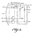
- FIGs 1 and 3 indicates the novel and improved refrigerator compressor system of this invention which is shown to include a refrigerator compressor 12 and an electrical motor 14 for operating the compressor which are mounted within an hermetically-sealed container 16.
- a coolant fluid 18 surrounds the compressor and motor within the container and a plurality of electrically conductive lead-through pins 20, 22 and 24 extend through a wall 16.1 of the container in spaced, electrically-insulated relation to the container and to each other for electrically connecting the motor in an electrical circuit.
- the compressor 12 is of a conventional rotary type, that type of compressor having been found to provide a temperature level within such a fluid-filled hermetically-sealed container which is substantially uniform throughout all parts of the container 16 during normal operation of the compressor 12 by the motor 14 as well as during undesirable increases in that temperature such as might result from operation of the motor during the occurrence of various fault conditions in the compressor system.
- the compressor 12 is of a rotary type as described in Handbook - 1983 Equipment, Part III Chapter 12, Published by ASHRAE 1983 and the compressor is arranged to be operated by a conventional electrical motor disposed within the sealed container 16 in a conventional manner.
- the fluid-fill coolant 18 comprises a conventional dielectric coolant fluid such as freon gas or the like which is maintained under pressure within the container 16 in conventional manner.
- the lead-through pins 20, 22 and 24 are embodied in a conventional fusite cap 26 having the pins secured in openings 26.1 in the cap in sealed, electrically-insulated relation to the cap and to each other by glass-sealing means 28, the cap being welded to the wall 16.1 of the container in conventional manner as indicated at 26.2.
- a novel and improved motor protector unit is mounted within the container 16 on the inner ends of the lead-through pins 20, 22 and 24 and is electrically connected in the electrical circuit of the motor 14 to be thermally responsive to changes in said substantially uniform temperature level in the container 16 for protecting the motor against overheating while also facilitating easy, economical and reliably assembly of the refrigerator compressor system.
- the motor protector unit 30 comprises a cluster block body 32 of a rigid electrical insulating material such as polycarbonate or the like and resilent, electrical contact means 34, 36 and 38 of any conventional type are disposed on the block for resiliently gripping and making electrical connection to the respective lead-through pins 20, 22 and 24.
- a thermally responsive motor protector element 40 of any conventional type such as the thermal and current-responsive protector shown in U.S. Patent 4,485,231 is mounted on the cluster block body so the motor protector is easily connected in the electrical circuit of the motor 14 and is disposed at a predetermined location in the container 16 to be responsive to said substantially uniform temperature in the container when the unit 30 is mounted on the lead-through pins as described.
- the protector 40 comprises any previously known motor protector element having thermally-responsive means movable within the protector in response to a selected rise in temperature of the thermally responsive means for opening an electrical circuit through the protector, the protector being adapted to be connected in a motor circuit for opening that motor circuit when the thermally responsive means move in response to said selected rise in temperature of the thermally responsive means.
- the cluster block 32 is formed in two sections 32.1 and 32.2 secured together by riveting or ultrasonic fusing or the like at 32.3 to form a chamber 32.4.
- Apertures 32.5 are provided in the block sections to fit over the respective lead-through pins 20, 22 and 24.
- the resilient contact means are located inside the chamber 32.4 by locating bosses 32.6 for disposing the contact means to resiliently grip the lead-through pins when the pins are inserted through the block apertures 32.5 as will be understood.
- the contact means each comprise resilient contact portions 34.1, 36.1, 38.1, welded to relatively rigid contact arms or blades 34.2, 36.2, 38.2 and lead wire means 42, 44 are connected at one end to two of the contact blades 34, 36 respectively to extend from the cluster block. Electrical terminals 42.1, 44.1 carried at the opposite ends of those lead wires are electrically connected to corresponding terminals on the motor 14 as shown in Figs 1 and 3.
- An additional resilient spring contact portion 38.3 is welded to an additional blade portion 38.4 of the remaining contact means and that blade portion extends from the cluster block through an aperture 32.7 so that the contact spring portion 38.3 resiliently grips and makes electrical connection to a terminal 40.1 of the motor protector outside the cluster block chamber 32.4.
- An additional lead wire 46 is connected at one end to a second terminal 40.2 of the motor protector and carries an additional terminal 46.1 at its opposite end connected to a corresponding terminal on the electrical motor 14.
- Preferably locating bosses 32.8 provide detent means 32.9 or the like for engaging the motor protector 40 and cooperating with the resilient contact spring portion 38.3 for detachably mounting the motor protector 40 on the motor protector unit 30.
- the motor protector unit 30 is of an economical structure. It is easily and economically mounted within the container 16 by fitting the cluster block aperture over the pins 20, 22 and 24 for detachably mounting the cluster block on the pins.
- the motor protector 40 carried on the protector unit 30 is of a conventional type. It is easily provided with a selected actuating temperature to be thermally responsive to a selected rise in a substantially uniform temperature level within the container 16 to interrupt the motor circuit and prevent overheating of the motor if such a rise in temperature should result from the occurrence of a fault condition in the motor or the refrigerator compressor system.
- the motor protector unit is easily and economically connected in the electrical circuit of the motor 14.
- the motor protector 40 is also easily and economically incorporated in that electrical circuit for interrupting the motor operation in response to such a selected rise in the temperature within the system container.
Landscapes
- Physics & Mathematics (AREA)
- Electromagnetism (AREA)
- Compressor (AREA)
- Applications Or Details Of Rotary Compressors (AREA)
- Control Of Positive-Displacement Pumps (AREA)
Applications Claiming Priority (2)
| Application Number | Priority Date | Filing Date | Title |
|---|---|---|---|
| US74515885A | 1985-06-17 | 1985-06-17 | |
| US745158 | 1985-06-17 |
Publications (2)
| Publication Number | Publication Date |
|---|---|
| EP0207679A2 true EP0207679A2 (fr) | 1987-01-07 |
| EP0207679A3 EP0207679A3 (fr) | 1989-05-17 |
Family
ID=24995498
Family Applications (1)
| Application Number | Title | Priority Date | Filing Date |
|---|---|---|---|
| EP86304638A Withdrawn EP0207679A3 (fr) | 1985-06-17 | 1986-06-16 | Système de compression de réfrigérateur et son unité de protection de moteur |
Country Status (2)
| Country | Link |
|---|---|
| EP (1) | EP0207679A3 (fr) |
| JP (2) | JP2748314B2 (fr) |
Cited By (1)
| Publication number | Priority date | Publication date | Assignee | Title |
|---|---|---|---|---|
| EP0279023A3 (en) * | 1987-02-20 | 1989-05-10 | Tecumseh Products Company | Compressor terminal block and overload protector assembly |
Families Citing this family (2)
| Publication number | Priority date | Publication date | Assignee | Title |
|---|---|---|---|---|
| KR100318596B1 (ko) * | 2000-03-20 | 2001-12-28 | 이충전 | 밀폐형 왕복동식 압축기용 릴레이 |
| JP2005163575A (ja) * | 2003-12-01 | 2005-06-23 | Matsushita Electric Ind Co Ltd | 密閉型電動圧縮機 |
Family Cites Families (4)
| Publication number | Priority date | Publication date | Assignee | Title |
|---|---|---|---|---|
| US3016183A (en) * | 1957-04-19 | 1962-01-09 | Gen Motors Corp | Refrigerating apparatus |
| US3586910A (en) * | 1969-05-19 | 1971-06-22 | White Consolidated Ind Inc | Internal hermetic motor protection system |
| US3622948A (en) * | 1970-02-06 | 1971-11-23 | Westinghouse Electric Corp | Electrical connector cluster assembly with motor protection |
| JPS6073899U (ja) * | 1983-10-28 | 1985-05-24 | 三洋電機株式会社 | 回転圧縮機の保護装置 |
-
1986
- 1986-06-16 EP EP86304638A patent/EP0207679A3/fr not_active Withdrawn
- 1986-06-17 JP JP61141211A patent/JP2748314B2/ja not_active Expired - Lifetime
-
1997
- 1997-11-18 JP JP09317323A patent/JP3121572B2/ja not_active Expired - Fee Related
Cited By (1)
| Publication number | Priority date | Publication date | Assignee | Title |
|---|---|---|---|---|
| EP0279023A3 (en) * | 1987-02-20 | 1989-05-10 | Tecumseh Products Company | Compressor terminal block and overload protector assembly |
Also Published As
| Publication number | Publication date |
|---|---|
| JP2748314B2 (ja) | 1998-05-06 |
| JP3121572B2 (ja) | 2001-01-09 |
| EP0207679A3 (fr) | 1989-05-17 |
| JPS6248991A (ja) | 1987-03-03 |
| JPH10196574A (ja) | 1998-07-31 |
Similar Documents
| Publication | Publication Date | Title |
|---|---|---|
| US5509786A (en) | Thermal protector mounting structure for hermetic refrigeration compressors | |
| US4748531A (en) | Compressor terminal block and overload protector assembly | |
| US4791329A (en) | Motor protector mounting structure for enclosed electric compressors | |
| US4167721A (en) | Hermetic motor protector | |
| JP4632187B2 (ja) | 圧縮機システム用保護装置 | |
| US4205246A (en) | Explosion resistant overload and relay mounting for explosion resistant motor | |
| EP0484077B1 (fr) | Dispositif de protection pour moteur de compresseur | |
| GB2193396A (en) | Three element gas tube protector module | |
| EP0207679A2 (fr) | Système de compression de réfrigérateur et son unité de protection de moteur | |
| US4380001A (en) | Electric safety device | |
| US4458231A (en) | Protector apparatus for dynamoelectric machines | |
| EP0375261A1 (fr) | Appareil combiné de démarrage et de protection d'un moteur | |
| US3431526A (en) | Miniature electrical switch | |
| JP2782173B2 (ja) | 密閉形電動圧縮機用保護装置 | |
| US6276969B1 (en) | Terminal connector for sealed electromotive compressors | |
| US3833873A (en) | Thermal protector | |
| JP2782168B2 (ja) | 密閉形電動圧縮機用保護装置 | |
| JPH07241061A (ja) | 密閉形電動圧縮機用プロテクタ | |
| KR200209503Y1 (ko) | 압축기 전동기용 과부하 보호 장치의 클러스터 블록 | |
| JP2003328939A (ja) | 密閉型電動圧縮機用インターナルプロテクタ | |
| JPH07147121A (ja) | 密閉形ヒューズ付プロテクタ | |
| JP2933198B2 (ja) | ヒュージブルリンク | |
| JP2743513B2 (ja) | サーマルプロテクタ | |
| JP2743512B2 (ja) | サーマルプロテクタ | |
| JPH1073082A (ja) | 密閉形電動圧縮機用プロテクタ |
Legal Events
| Date | Code | Title | Description |
|---|---|---|---|
| PUAI | Public reference made under article 153(3) epc to a published international application that has entered the european phase |
Free format text: ORIGINAL CODE: 0009012 |
|
| AK | Designated contracting states |
Kind code of ref document: A2 Designated state(s): DE FR GB IT NL SE |
|
| PUAL | Search report despatched |
Free format text: ORIGINAL CODE: 0009013 |
|
| AK | Designated contracting states |
Kind code of ref document: A3 Designated state(s): DE FR GB IT NL SE |
|
| 17P | Request for examination filed |
Effective date: 19890828 |
|
| 17Q | First examination report despatched |
Effective date: 19901008 |
|
| STAA | Information on the status of an ep patent application or granted ep patent |
Free format text: STATUS: THE APPLICATION IS DEEMED TO BE WITHDRAWN |
|
| 18D | Application deemed to be withdrawn |
Effective date: 19920429 |
|
| RIN1 | Information on inventor provided before grant (corrected) |
Inventor name: D'ENTREMONT, JOHN R. |