EP0209645B1 - Système de séparation à haut rendement - Google Patents
Système de séparation à haut rendement Download PDFInfo
- Publication number
- EP0209645B1 EP0209645B1 EP86105486A EP86105486A EP0209645B1 EP 0209645 B1 EP0209645 B1 EP 0209645B1 EP 86105486 A EP86105486 A EP 86105486A EP 86105486 A EP86105486 A EP 86105486A EP 0209645 B1 EP0209645 B1 EP 0209645B1
- Authority
- EP
- European Patent Office
- Prior art keywords
- high efficiency
- air
- grinding
- separator
- efficiency separator
- Prior art date
- Legal status (The legal status is an assumption and is not a legal conclusion. Google has not performed a legal analysis and makes no representation as to the accuracy of the status listed.)
- Expired
Links
- 239000000463 material Substances 0.000 claims description 132
- 238000000227 grinding Methods 0.000 claims description 104
- 239000002245 particle Substances 0.000 claims description 60
- 239000000428 dust Substances 0.000 claims description 37
- 238000002156 mixing Methods 0.000 claims description 27
- 230000000694 effects Effects 0.000 claims description 13
- 230000005484 gravity Effects 0.000 claims description 7
- 238000007599 discharging Methods 0.000 claims description 2
- 230000003134 recirculating effect Effects 0.000 claims description 2
- 239000004568 cement Substances 0.000 description 33
- 238000010276 construction Methods 0.000 description 11
- 239000010419 fine particle Substances 0.000 description 10
- 238000000926 separation method Methods 0.000 description 7
- 238000011084 recovery Methods 0.000 description 6
- VYPSYNLAJGMNEJ-UHFFFAOYSA-N Silicium dioxide Chemical compound O=[Si]=O VYPSYNLAJGMNEJ-UHFFFAOYSA-N 0.000 description 4
- 239000006185 dispersion Substances 0.000 description 4
- 241001344923 Aulorhynchidae Species 0.000 description 3
- 239000000203 mixture Substances 0.000 description 3
- 238000012986 modification Methods 0.000 description 3
- 230000004048 modification Effects 0.000 description 3
- 239000011343 solid material Substances 0.000 description 3
- 239000000126 substance Substances 0.000 description 3
- XEEYBQQBJWHFJM-UHFFFAOYSA-N Iron Chemical compound [Fe] XEEYBQQBJWHFJM-UHFFFAOYSA-N 0.000 description 2
- CDBYLPFSWZWCQE-UHFFFAOYSA-L Sodium Carbonate Chemical compound [Na+].[Na+].[O-]C([O-])=O CDBYLPFSWZWCQE-UHFFFAOYSA-L 0.000 description 2
- 238000001816 cooling Methods 0.000 description 2
- 238000009792 diffusion process Methods 0.000 description 2
- 235000013305 food Nutrition 0.000 description 2
- -1 i.e. Chemical class 0.000 description 2
- 238000005259 measurement Methods 0.000 description 2
- JTJMJGYZQZDUJJ-UHFFFAOYSA-N phencyclidine Chemical class C1CCCCN1C1(C=2C=CC=CC=2)CCCCC1 JTJMJGYZQZDUJJ-UHFFFAOYSA-N 0.000 description 2
- 239000000843 powder Substances 0.000 description 2
- 239000004576 sand Substances 0.000 description 2
- 239000007921 spray Substances 0.000 description 2
- 239000005995 Aluminium silicate Substances 0.000 description 1
- 229910000906 Bronze Inorganic materials 0.000 description 1
- RYGMFSIKBFXOCR-UHFFFAOYSA-N Copper Chemical compound [Cu] RYGMFSIKBFXOCR-UHFFFAOYSA-N 0.000 description 1
- 229920002261 Corn starch Polymers 0.000 description 1
- 244000068988 Glycine max Species 0.000 description 1
- 235000010469 Glycine max Nutrition 0.000 description 1
- 235000019738 Limestone Nutrition 0.000 description 1
- 229920002472 Starch Polymers 0.000 description 1
- 244000299461 Theobroma cacao Species 0.000 description 1
- 235000009470 Theobroma cacao Nutrition 0.000 description 1
- 229910045601 alloy Inorganic materials 0.000 description 1
- 239000000956 alloy Substances 0.000 description 1
- 235000012211 aluminium silicate Nutrition 0.000 description 1
- 230000003190 augmentative effect Effects 0.000 description 1
- 239000010974 bronze Substances 0.000 description 1
- 235000012839 cake mixes Nutrition 0.000 description 1
- AXCZMVOFGPJBDE-UHFFFAOYSA-L calcium dihydroxide Chemical compound [OH-].[OH-].[Ca+2] AXCZMVOFGPJBDE-UHFFFAOYSA-L 0.000 description 1
- 239000000920 calcium hydroxide Substances 0.000 description 1
- 235000011116 calcium hydroxide Nutrition 0.000 description 1
- 229910001861 calcium hydroxide Inorganic materials 0.000 description 1
- 239000012141 concentrate Substances 0.000 description 1
- 239000004567 concrete Substances 0.000 description 1
- 229910052802 copper Inorganic materials 0.000 description 1
- 239000010949 copper Substances 0.000 description 1
- KUNSUQLRTQLHQQ-UHFFFAOYSA-N copper tin Chemical compound [Cu].[Sn] KUNSUQLRTQLHQQ-UHFFFAOYSA-N 0.000 description 1
- 239000008120 corn starch Substances 0.000 description 1
- 238000010586 diagram Methods 0.000 description 1
- 238000001035 drying Methods 0.000 description 1
- 238000010410 dusting Methods 0.000 description 1
- 230000008030 elimination Effects 0.000 description 1
- 238000003379 elimination reaction Methods 0.000 description 1
- 235000013312 flour Nutrition 0.000 description 1
- 239000012535 impurity Substances 0.000 description 1
- 239000004615 ingredient Substances 0.000 description 1
- 229910052742 iron Inorganic materials 0.000 description 1
- NLYAJNPCOHFWQQ-UHFFFAOYSA-N kaolin Chemical compound O.O.O=[Al]O[Si](=O)O[Si](=O)O[Al]=O NLYAJNPCOHFWQQ-UHFFFAOYSA-N 0.000 description 1
- 239000006028 limestone Substances 0.000 description 1
- 238000004519 manufacturing process Methods 0.000 description 1
- 235000012054 meals Nutrition 0.000 description 1
- 239000002184 metal Substances 0.000 description 1
- 229910052751 metal Inorganic materials 0.000 description 1
- 238000000034 method Methods 0.000 description 1
- 235000013336 milk Nutrition 0.000 description 1
- 239000008267 milk Substances 0.000 description 1
- 210000004080 milk Anatomy 0.000 description 1
- 239000004570 mortar (masonry) Substances 0.000 description 1
- 239000002367 phosphate rock Substances 0.000 description 1
- 239000012254 powdered material Substances 0.000 description 1
- 230000000063 preceeding effect Effects 0.000 description 1
- 238000012545 processing Methods 0.000 description 1
- 102000004169 proteins and genes Human genes 0.000 description 1
- 108090000623 proteins and genes Proteins 0.000 description 1
- 239000000377 silicon dioxide Substances 0.000 description 1
- 235000017550 sodium carbonate Nutrition 0.000 description 1
- 229910000029 sodium carbonate Inorganic materials 0.000 description 1
- 239000001488 sodium phosphate Substances 0.000 description 1
- 229910000162 sodium phosphate Inorganic materials 0.000 description 1
- 235000000346 sugar Nutrition 0.000 description 1
- 239000000454 talc Substances 0.000 description 1
- 229910052623 talc Inorganic materials 0.000 description 1
- 238000012360 testing method Methods 0.000 description 1
- RYFMWSXOAZQYPI-UHFFFAOYSA-K trisodium phosphate Chemical compound [Na+].[Na+].[Na+].[O-]P([O-])([O-])=O RYFMWSXOAZQYPI-UHFFFAOYSA-K 0.000 description 1
- 238000005406 washing Methods 0.000 description 1
- XLYOFNOQVPJJNP-UHFFFAOYSA-N water Substances O XLYOFNOQVPJJNP-UHFFFAOYSA-N 0.000 description 1
- 229940100445 wheat starch Drugs 0.000 description 1
Images


Classifications
-
- B—PERFORMING OPERATIONS; TRANSPORTING
- B02—CRUSHING, PULVERISING, OR DISINTEGRATING; PREPARATORY TREATMENT OF GRAIN FOR MILLING
- B02C—CRUSHING, PULVERISING, OR DISINTEGRATING IN GENERAL; MILLING GRAIN
- B02C23/00—Auxiliary methods or auxiliary devices or accessories specially adapted for crushing or disintegrating not provided for in preceding groups or not specially adapted to apparatus covered by a single preceding group
- B02C23/18—Adding fluid, other than for crushing or disintegrating by fluid energy
- B02C23/24—Passing gas through crushing or disintegrating zone
- B02C23/32—Passing gas through crushing or disintegrating zone with return of oversize material to crushing or disintegrating zone
Definitions
- This invention relates to systems of the type that are operative to grind material as well as to separate the ground material into a finished product containing particles which are of a predetermined size, and in particular to a high efficiency separator system which embodies a high efficiency mechanical air separator.
- systems of the type to which the present invention is directed will be viewed as being composed essentially of two major operating components; namely, a grinding device and a separator device.
- a grinding device it has long been known in the prior art to provide apparatus which are employable for purposes of effectuating the grinding of materials.
- the prior art is replete with examples of various types of apparatus that have been used heretofore to effect the grinding of a multiplicity of different kinds of materials.
- discernible differences of a structural nature can be found to exist between individual ones of the aforesaid apparatus.
- separator devices as the name given thereto implies, the function of a separator device is to effectuate in some preestablished fashion a separation of material which is made to enter the separator device.
- Apparatus have long be known to be available in the prior art which are suitable for use for such a purpose.
- one such apparatus is that known to those skilled in the art of separator devices as a mechanical air separator.
- Applicant's assignee is a manufacturer of such mechanical air separators.
- the material which is to undergo separation enters a hollow shaft, or center feed pipe, at the top of the mechanical air separator and under the influence of gravity drops upon a rotating distributor plate which is suitably positioned therebelow.
- the distributor plate disperses the material into the upward sweep of circulating air which is suitably developed by a fan located in the top chamber of the mechanical air separator.
- One or more whizzer blades are operative to bring about a centrifugal motion of the air and the material.
- the effect thereof in turn is to concentrate the oversize material along the inner cone of the mechanical air separator whereupon the oversized material passes out of a tailings spout which is located at the bottom of the mechanical air separtor.
- the air and powdered material of the desired fineness moves through the fan and is delivered into the outer cone chamber of the mechanical air separtor whereupon the fines are discharged from the mechanical air separator as finished product.
- the air after the fines have been released in the outer cone, returns through the deflector ports with which the mechanical air separator is provided to the inner cone thereby establishing a continuous circulation of the flow of air.
- such mechanical air separators have been successfully employed in closed circuit grinding operations for classifying, and drying where desired, raw mix, and classifying, and cooling, finished cement; for producing limestone sand to meet close specifications of granular sand material to be used in bituminous concrete, mortar, as an aggregate and many other uses; for making fine, uniform cake mixes and for the production of protein-enriched grades of flour; for producing a high fineness, uniformly classified, hydrated lime for chemical and spray purposes; for classifying numerous food products including sugar, cocoa, milk powder, food mixtures with various ingredients, corn starch and wheat starch, and soya bean meal; in applications where manufactured chemicals are required in closely sized form, i.e., for making the various grades ranging from extremely fine to the granular dust-free gradations of such chemicals as soda ash and sodium phosphate; in the beneficiation of certain materials such as talc, kaolin and clays, and phosphate rock for purposes of removing therefrom impurities in the form of si
- the mechanical air separator may be connected either in closed circuit relation or in open circuit relation therewith.
- the mechanical air separator is designed to skim off the fines as fast as they are produced such that the grinding device works only on fresh material without wasting power. The tailings from the mechanical air separator, however, are discharged back to the grinding device for further reduction.
- the reground material After being reground in the grinding device, the reground material is returned to the mechanical air separator along with the feed that is being supplied thereto so that a constant circulating load is established between the grinding device and the mechanical air separator.
- the mechanical air separator In contradistinction to the manner in which the mechanical air separator is made to interact with the grinding device when the former is connected in closed circuit relation therewith, when the mechanical air separator is connected in open circuit relation with the grinding device the ground material is supplied from the grinding device in the form of feed to the mechanical air separator but the tailings from the mechanical air separator are not recirculated to the grinding device for further reduction in the grinding device.
- particle size analyzers have become available that can analyze samples very quickly. They also provide a complete particle size distribution for the sample. This in turn has permitted an extensive study of the performance of mechanical air separator to be undertaken at a reasonable cost. In addition, it has permitted results to be based on the complete particle size distribution and has enabled errors to be recognized.
- the term factional recovery refers to the percentage of the material of a given particle size or between two particle sizes which is present in the feed to the mechanical air separator and which is recovered in the finished product from the mechanical air separator.
- a "Tromp Curve” is one way of measuring the efficiency of a mechanical air separator.
- a perfect mechanical air separator i.e., one having an efficiency of 100%, would have a "Tromp Curve” that would be a vertical line at the "cut point" particle size. That is, everything in the finished product would be finer than this cut point particle size and everything in the tailings would be coarser.
- bypassing is defined as being the difference between a numerical value of 100% and the amount of fractional recovery that is actually attained at the finest particle sizes. Based on test results, it has been determined that mechanical air separators with low circulating loads have the least bypass, i.e., are the most efficient, whereas mechanical air separators with high circulating loads have the greatest bypass, i.e., are the least efficient.
- Bypassing is alleged to be caused by one or more of the following three events.
- One of these is the internal recirculation of fines.
- a second is the inadequate dispersion of the feed in the air prior to the feed reaching the classifying zone of the mechanical air separator.
- the third is the existence of an excessive material/air ratio which has the effect of causing interference between particles within the classifying zone of the mechanical air separator.
- the cyclone separator has been marketed in an attempt to alleviate the first of the three causes of bypassing that has been enumerated above.
- the cyclone separators that have been marketed utilize relatively low efficiency cyclones, i.e., cyclones having an efficiency of between 88 and 92%, and thus the effect thereof is than fines are still recirculated to the separator.
- such cyclone separators have not addressed the second cause of bypassing that has been enumerated above.
- the rather small improvement in efficiency achieved with the cyclone type separator generally has not justified the high capital cost of such cyclone separators.
- an object of the present invention to provide a new and improved high efficiency separator system that is operative both to grind material and to thereafter separate the ground material into a finished product which contains particles that are of a predetermined size.
- a further object of the present invention is to provide such a new and improved high efficiency separator system wherein a characteristic of the high efficiency mechanical air separator that is employed therein is that air is passed through the high efficiency mechanical air separator only once thereby preventing the internal recirculation of fines therethrough, which has been identified to be a cause of bypass.
- a still further object of the present invention is to provide such a new and improved high efficiency separator system wherein a characteristic of the new and improved high efficiency mechanical air separator that is employed therein is that the flow of air therethrough is controlled so that a high velocity mixing zone is established therein whereby excellent mixing of the air and the feed material is achieved prior to the feed material reaching the classifying zone within the high efficiency mechanical air separator thus ensuring the avoidance of inadequate dispersion of the feed material in the air, which has been identified to be a cause of bypass.
- Yet another object of the present invention is to provide such a new and improved high efficiency separator system wherein a characteristic of the new and improved high efficiency mechanical air separator that is employed therein is that a maximum limit is established for the material/air ratio employed therewith in an effort to prevent the occurrence of interference between particles in the classifying zone of the high efficiency mechanical air separator, which has been identified to be a cause of bypass.
- Yet still another object of the present invention is to provide such a new and improved high efficiency separator system which is characterized in that through the use thereof economies in power consumption in the grinding circuit are capable of being realized and a steeper particle size distribution in the finished product is capable of being achieved.
- Yet still a further object of the present invention is to provide such a new and improved high efficiency separator system wherein a characteristic of the new and improved high efficiency mechanical air separator that is employed therein is that the latter is suitable for use both in new applications and in retrofit applications.
- a new and improved high efficiency separator system that is operative both to grind material and to thereafter separate the ground material into a finished product which contains particles that are of a predetermined size.
- the subject high efficiency separator system comprises grinding means, high efficiency separator means, dust collector means and fan means.
- the grinding means is operative to effectuate the grinding therewithin of the material fed thereto.
- the high efficiency separator means is connected in flow relation with the grinding means for receiving therefrom all of the material ground in the grinding means as well as all of the air vented from the grinding means.
- the high efficiency separator means is operative to effectuate therewithin a classification of the ground material supplied thereto from the grinding means and for recirculating in the form of tailings to the grinding means for further reduction therein ground material containing particles exceeding a predetermined size.
- the dust collector means is connected in flow relation with the high efficiency separator means for receiving therefrom in the form of finished product entrained in air ground material containing particles that are of a predetermined particle size.
- the dust collector means is operative for separating the ground material particles from the air and for discharging therefrom as separate entities both the ground material particles in the form of finished product and the air that has had the ground material products removed therefrom.
- the fan means is connected in flow relation with the dust collector means for receiving therefrom the air discharged from the dust collector means.
- the high efficiency separator means includes housing means, whizzer blade means, a feed material inlet means, an air inlet means and discharge means.
- the housing means includes a drum portion and a cone portion. The cone portion has one end thereof joined to one end of the drum portion.
- the whizzer blade means is supported for rotation at a first location within the housing means.
- the whizzer blade means defines a classification zone within the housing means.
- the whizzer blade means is operative to effect a classification based on particle size of feed material into a finished product as the feed material entrained in air passes through the classification zone.
- the feed material inlet means is supported in the housing means.
- the air inlet means is supported in the cone portion for supplying into the interior of the housing means air at a predetermined rate so as to ensure the existence of a predefined material to air ratio within the housing means.
- the discharge means is formed in the cone portion of the housing means.
- the discharge means is operative for effectuating the discharge from the high efficiency separator means of the tailings that remain following the classification within the classification zone of the feed material into finished product by the whizzer blade means.
- the high efficiency separator system is characterized in that the high efficiency separator means further includes a distributor plate means.
- the distributor plate means is positioned within the housing means at a second location and so as to define between the periphery of the distributor plate means and the internal surface of the housing means an annular passage operative as a high velocity mixing zone.
- the distributor plate means is supported from the whizzer blade means in spaced relation thereto and so as to be rotatable therewith.
- the distributor plate means is operative to cause the feed material disposed thereon to be dispersed under the influence of gravity into the high velocity mixing zone.
- the feed material inlet means is operative to supply feed material on to the distributor plate means.
- the feed material inlet means is coaxially aligned with the whizzer blade means and has a first end thereof projecting outwardly of the housing means and a second end thereof terminating at a point intermediate the first location of the whizzer blade means and the second location of the distributor plate means.
- the air inlet means has a first end thereof projecting outwardly of the cone portion and a second end thereof terminating at a point spaced from and aligned with the feed material inlet means such that the air exiting from the second end of the air inlet means follows a once-through flow path within the housing means before exiting therefrom and in the course of doing so is made to pass through the high velocity mixing zone at a high velocity so as to effect the entrainment therewith of the feed material dispersed into the high velocity mixing zone by the distributor plate means.
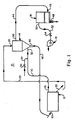
- a high efficiency separator system constructed in accordance with the present invention. More specifically, there is depicted in Figure 1 a high efficiency separator system 10 that includes a grinding means, generally designated by the reference numeral 12; a high efficiency separator means, generally designated by the reference numeral 14, and the nature of the construction and the mode of operation of which represents another aspect of inventive subject matter in accordance with the present invention; a dust collector means, generally designated by the reference numeral 16; and a fan means, generally designated by the reference numeral 18.
- the grinding means 12, the high efficiency separator means 14, the dust collector means 16 and the fan means 18 are all interconnected one to another in such a manner so as to define a predetermined flow path to which further reference will be had hereinafter.
- the high efficiency separator system 10 of Figure 1 is designed to be operative both to grind material and to thereafter separate the ground material into a finished product which embodies particles that are of a predetermined size.
- the mode of operation of the high efficiency separator system 10 of Figure 1 simply stated, is such that material which is to be ground is fed to the grinding means 12 wherein the material undergoes grinding. After being ground in the grinding means 12, the material is fed in the form of feed material to the high efficiency separator means 14. Within the high efficiency separator means 14, a separation is had of the finer feed material form the coarser feed material.
- the finer feed material is fed on to the dust collector means 16 and ultimately is discharged therefrom as finished product which embodies particles that are of a predetermined size.
- the coarser feed material is recirculated from the high efficiency separator means 14 to the grinding means 12 for additional grinding.
- the grinding means 12 may take the form of any suitable conventional form of grinding device that is commonly found utilized for purposes of effecting the grinding of solid materials such as cement.
- such grinding devices as ball mills of the type that are manufactured by many manufacturers. Since the nature of the construction as well as the mode of operation of such ball mills is well-known to those skilled in the art of the grinding of materials, it is not deemed necessary to set forth a detailed description thereof herein or to include an illustration thereof in the drawing. Rather, it is deemed sufficient for purposes of obtaining an understanding of the subject matter of the present invention to simply note herein that the function of the grinding means 12 is to effect the grinding of the solid material such as cement that is fed thereto.
- the high efficiency separator system 10 is particularly suited for use in processing a material such as cement
- a material such as cement
- the solid material which is processed therewithin will be deemed to be cement.
- cement in the required quantity and at the required rate is supplied from a suitable source of supply thereof (not shown) to the grinding means 12 by any suitably sort of transport means, the latter being operable to effect an interconnection of the supply source (not shown) of cement with the inlet means, denoted in Figure 1 by the reference numeral 20, of the grinding means 12.
- the cement is conveyed therethrough by means of a flow of gas.
- This gas which preferably is air, is supplied through any suitable conventional means to the grinding means 12.
- the air which is employed in the conveyance of the cement through the grinding means 12, is fed to the grinding means 12 through conduit means (not shown) such that the air is made to enter the grinding means 12 through the inlet means that has been denoted in Figure 1 of the drawing by means of the reference numeral 20.
- the cement After being ground in the grinding means 12, the cement is discharged therefrom through the outlet means that has been denoted in Figure 1 by the reference numeral 22. Upon being so discharged from the grinding means 12 though the outlet means 22 thereof, the cement is transported to the high efficiency separator means 14 through the use of any suitable form of conventional transport means, the latter being schematically illustrated in Figure 1 wherein the transport means has been identified by the reference numeral 24.
- One form that the transport means 24 can take is that of a bucket elevator.
- the cement On reaching the high efficiency separator means 14, the cement is made to enter the latter through inlet means, seen at 26 in Figure 1, with which the high efficiency separator means 14 is suitably provided for this purpose. Note is made here of the fact that the inlet means 26 is located at the top of the high efficiency separator means 14. The significance of the location of the inlet means 26 will become more readily apparent as a discussion is had hereinafter of the nature of the construction and the mode of operation of the high efficiency separator means 14, which is to be found illustrated in more detail in Figures 2
- the latter as can be seen with reference to Figure 1 of the drawing is provided with a second outlet means, the latter being denoted in Figure 1 by the reference numeral 28. It is through this second outlet means 28 that the air which has been employed for purposes of effectuating the conveyance of the cement through the grinding means 12 is vented therefrom.
- the vented air is supplied to the high efficiency separator means 14 through the use of any conventional form of conveyance means that is suitable for use for such a purpose.
- This conveyance means can be found illustrated in Figure 1 of the drawing wherein the conveyance means is identified by the reference numeral 30.
- This air which is vented from the grinding means 12 through the outlet means 28 commonly has entrained therewithin fine particles. In accord with the mode of operation of the high efficiency separator system 10 of the present invention constructed as illustrated in Figure 1 of the drawing, no attempt is made to separate these fine particles from the air vented from the grinding means 12 prior to the vented air reaching the high efficiency separator means 14.
- the air vented from the grinding means 12 is made to enter the high efficiency separator means 14 through a second inlet means, seen at 32 in Figure 1, with which the high efficiency separator means 14 is suitably provided.
- a second inlet means seen at 32 in Figure 1, with which the high efficiency separator means 14 is suitably provided.
- the inlet means 26 note is also made here of the location of the inlet means 32 which as can be seen with reference to Figure 1 of the drawing is located in the lower section of the high efficiency separator means 14. The significance of this location will become clearer from the description of the nature of the construction and the mode of operation of the high efficiency separator means 14 which can be found set forth hereinafter in connection with a discussion of Figures 2 and 3 of the drawing.
- the air vented from the grinding means 12 may be augmented by makeup air. More specifically, such makeup air may be introduced into the conveyance means 30 through the conduit means which is schematically illustrated in Figure 1, and which can be found denoted in Figure 1 by the reference numeral 34.
- valve means in order to control the amount of makeup air which is supplied for this purpose, the conduit means 34 is preferably provided by valve means, the latter being identified in Figure 1 by the reference numeral 36.
- the valve means 36 may take the form of any conventional form of valve means that is suitable for use for such a purpose.
- the feed material e.g., cement
- the feed material that has been ground in the grinding means 12 enters the high efficiency separator means 14 through the inlet means 26.
- the cement in a manner which will be more fully described hereinafter, is caused to flow to a high velocity mixing zone within the high efficiency separator means 14.
- the air which enters the high efficiency separator means 14 through the inlet means 32 in a manner which will be described moe fully hereinafter, is also caused to flow to the aforereferenced high velocity mixing zone.
- this high velocity mixing zone the particles of cement become entrained in the flow of air.
- a very important characteristic of this mixing zone with which the high efficiency separator means 14 is provided in a manner yet to be described is that by virtue of the flow of high velocity air therethrough an excellent mixture of air and cement particles is achieved such that very little, if any, of the cement paricles fail to become entrained in the flow of air thereby minimizing the likelihood that bypass occasioned by the inadequate dispersion of the cement particles in the air flow will occur. Thereafter, the combined stream of air and cement particles is made to flow in a manner that will be described hereinafter to the classifying zone of the high efficiency separator means 14.
- a classification is had of the stream of air and cement particles such that the cement particles which are of the desired particle size while still entrained within the stream of air are caused to be discharged along with the stream of air through the outlet means with which, as schematically illustrated at 38 in Figure 1, the high efficiency separator means 14 is suitably provided.
- the coarser particles of cement i.e., those which are not of the desired particle size are caused to be dischared from the high efficiency separator means 14 through a tailings spout with which the high efficiency separator means 14 is suitably provided and which preferably terminates in a double flap valve, the latter being denoted in Figure 1 of the drawing by the reference numeral 40.
- the double flap valve 40 is operative as the means by which the coarser cement particles, i.e., tailings, are allowed to discharge from the high efficiency separator means 14 while allowing a minimal amount of infiltrating air to enter the unit.
- the tailings From the high efficiency separator means 14, the tailings, as will be best understood with reference to Figure 1 of the drawing, are recirculated back to the grinding means 12 for further reduction. More specifically, the tailings from the high efficiency separator means 14, after being made to pass through the double flap valve 40, are conveyed by means of any conventional form of conveyance means, the latter being schematically illustrated in Figure 1 of the drawing wherein the conveyance means can be found identified by the reference numeral 42, that is suitable for use for such a purpose. As seen with reference to Figure 1 of the drawing, the tailings that are recirculated by means of conveyance means 42 from the high efficiency separator means 14 to the grinding means 12 are made to enter the latter through inlet means 26 to which reference has herein previously been had.
- the tailings in known fashion are subjected to additional grinding whereupon after being reground the tailings are discharged from the grinding means 12 through the outlet means 22 and once again are fed back to the high efficiency separator means 14 wherein the manner to which reference has previously been had herein there is effectuated a classification of the ground material into that which is comprised of particles of the desired size and that which is comprised of particles that exceed the desired size.
- the fine particles while still entrained in the air stream exit from the high efficiency separator means 14 through the outlet means 38 and are transported to the dust collector means 16 by means of any conventional form of transport means, the latter being schematically depicted in Figure 1 wherein the designation thereof has been had by means of the reference numeral 44, that is suitable for use for the aforedescribed purpose.
- the combined stream of air and fine particles enters the dust collector means 16 through an inlet means, denoted in Figure 1 of the drawing by the reference numeral 46, with which the dust collector means 16 is suitably provided for this purpose.
- the dust collector means 16 is designed to be operative to accomplish in known fashion the separation of the fine particles from the stream of air.
- the dust collector means 16 may take the form of any suitable conventional form of dust collector device that is commonly found employed for purposes of effectuating the separation of fine particles from a gaseous stream. Since the nature of the construction as well as the mode of operation of such dust collector devices is well-known to those skilled in the art, it is not deemed necessary to set forth a detailed description thereof herein or to include an illustration thereof in the drawing.
- the function of the dust collector means 16 is to cause in known fashion a separation to be had from the air stream of the fine particles that are entrained therewithin.
- the fine particles which in accordance with the description that has been set forth hereinbefore of the high efficiency separator system 10 constitute cement particles, are discharged from the dust collector means 16 in the form of finished product through an outlet means with which the dust collector means 16 is suitably provided and which in accord with the present invention terminates in valve means, the latter being identified in Figure 1 by the reference numeral 48.
- the valve means 48 may take the form of any conventional type of valve means that is known to be capable of being employed for the aforedescribed purpose.
- the valve means 48 is designed to be operative to control the rate at which the finished product is discharged from the dust collector means 16 and concomitantly from the high efficiency separator system 10.
- the air which remains after the fine particles are removed therefrom is discharged from the dust collector means 16 through an outlet means, denoted in Figure 1 by the reference numeral 50 with which the dust collector means 16 is suitably provided for this purpose.
- this air upon being discharged from the dust collector means 16 is drawn, i.e., caused to be conveyed, therefrom by virtue of the action of the fan means 18.
- the outlet means 50 of the dust collector means 16 is interconnected with the fan means 18 by means of conduit means, the latter being schematically shown in Figure 1 of the drawing wherein the conduit means has been identified by the reference numeral 52.
- the conduit means 52 may take the form of any conventional type of conduit means that is suitable for use for such a purpose.
- valve means there is preferably employed along the length of the conduit means 52 suitable valve means, the latter being depicted at 54 in Figure 1 of the drawing, such as to be located in interposed relation between the dust collector means 16 and the fans 18.
- the fan means 18 may take the form of any conventional type of fan device that is capable of being employed as a system fan in a system of the type depicted in Figure 1.
- the high efficiency separator system 10 of the present invention includes grinding means 12, high efficiency separator means 14, dust collector means 16 and fan means 18 all of which are interconnected in a predefined flow path.
- the grinding means 12 of the subject high efficiency separator system 10 includes inlet means 20 through which the material to be ground therewithin is fed thereto, a first outlet means 28 through which the air vented from the grinding means 12 exits therefrom, and a second outlet means 22 through which the material ground within the grinding means 12 exits therefrom.
- the high efficiency separator means 14 of the subject high efficiency separator system 10 includes a first inlet means 26 connected in flow relation with the second outlet means 22 of the grinding means 12 and through which the material ground in the grinding means 12 is made to enter the high efficiency separator means 14, a second inlet means 32 connected in flow relation with a first outlet means 28 of the grinding means 12 for receiving from the grinding means 12 the air vented therefrom as well as any makeup air that may be deemed to be required, a first outlet means 38 through which the product being vented from the high efficiency separator means 14 exits therefrom, and a second outlet means terminating in a double flap valve 40 connected in flow relation with the inlet means 20 of the grinding means 12 and through which the tailings are discharged from the high efficiency separator means 14 and recirculated to the grinding means 12.
- the dust collector means 16 includes inlet means 46 connected in flow relation with the first outlet means 38 of the high efficiency separator means 14 through which the product vented from the high efficiency separator means 14 is fed to the dust collector means 16, a first outlet means terminating in valve means 48 through which ground material embodying particles of the desired size is discharged as finished product from the dust collector means 14 and thus concomitantly from the subject high efficiency separator system 10, and a second outlet means 50 which is connected in flow relation with the fan means 18, the latter being designed to be operative as a system fan.
- the high efficiency separator means 14 comprises a new and improved form of high efficiency mechanical air separator.
- the same reference numerals which have been employed in Figure 1 of the drawing for purposes of identifying various features of a structural nature that the high efficiency separator means 14 embodies have also been utilized to designate these same features in Figures 2 and 3 of the drawing to the extent that they appear as well therein.
- the high efficiency separator means 14 constructed in accordance with the present invention includes a housing means, the latter being denoted generally in Figures 2 and 3 by the reference numeral 56.
- the housing means 56 embodies a generally cylindrical configuration.
- the housing means 56 has suitably formed therewithin for purposes yet to be described both an outer drum, the latter being denoted in Figure 2 by the reference numeral 58, and an inner drum, the latter being denoted by the reference numeral 60 in Figure 2.
- Cooperatively associated with the inner drum 60 as shown in Figure 2 is in turn a lower cone which is identified in Figure 2 by the reference numeral 62.
- a pair of whizzer blades seen in Figure 2 at 64 and 66, are suitably mounted within the inner drum 60 for rotation therewithin.
- a distributor plate cooperatively associated with the whizzer blades 64 and 66 is a distributor plate, the latter being identified in Figure 2 by the reference numeral 68. More specifically, the distributor plate 69 is suitably supported for rotation approximately at the location whereat the lower cone 62 is joined to the inner drum 60.
- any conventional form of motor drive means that is capable of being employed to impart rotation to disc-like members may, without departing from the essence of the present invention, be utilized for purposes of imparting to the whizzer blades 64 and 66 as well as the distributor plate 68 the rotation which it is desired to have these members undergo.
- the whizzer blades 64 and 66 are each suitably supported from a tube-like structure, the latter being denoted generally by the reference numeral 70 in Figure 2.
- the distributor plate 68 is suitably supported from the whizzer blade 64 through the use of any conventional form of support means such as to be rotatable with the whizzer blade 64.
- the tube-like structure 70 is rotatably driven by motor means, the latter being identified generally in Figure 2 by the reference numeral 72.
- the tube-like structure 70 is designed to be operative in the manner of a feed pipe.
- the tube-like structure 70 may be viewed as comprising the inlet means 26 of the high efficiency separator means 14 to which reference has been had hereinbefore in connection with the description of the nature of the construction and the mode of operation of the high efficiency separator system 10, which is to be found illustrated in Figure 1 of the drawing. That is, the tube-like structure 70 is provided with a hollow interior, and it is through the hollow interior of the tube-like structure 70 that the material, which for purposes of the present discussion has been deemed to be cement, ground in the grinding means 12 of the high efficiency separator system 10 enters the housing means 56 of the high efficiency separator means 14.
- the feed material After entering the tube-like structure 70, and more specifically the hollow interior thereof, the feed material falls the length of the tube-like structure 70 under in influence of gravity and drops onto the distributor plate 68. Mention is made here of the fact that the tube-like structure 70 terminates at a point which is located approximately within the plane defined by the whizzer blade 64, which in turn is suitably spaced as seen with reference to Figure 2 from the plane defined by the distributor plate 68. As such feed material upon leaving the tube-like structure 70 is caused to be dispersed upon the distributor plate 68, which as has been noted previously herein is undergoing rotation.
- an air diffuser seen at 76 in Figure 2 is preferably mounted through the use of any conventional form of support means at the downstream terminus of the air inlet 74.
- the air diffuser 76 in turn is designed to be operative to effect for a purpose to be described subsequently a diffusion of the air as the air exits from the air inlet 74.
- the air After undergoing diffusion by the air diffuser 76, the air continues to flow in an upwardly direction within the housing means 56 of the high efficiency separator means 14 until it reaches a high velocity mixing zone, the latter being denoted in Figure 2 of the drawing by the reference numeral 78. It is within this high velocity mixing zone 78 that the feed material dropping on to the rotating distributor plate 68 becomes entrained in the air flow in a manner to which further reference will be had hereinafter. Suffice it to say at this point, however, that the existence of the high velocity mixing zone 78 within the high efficiency separator means 14 serves to advantageously characterize the operation of the high efficiency separator means 14 by virtue of the fact that one of the known causes of bypass is virtually eliminated thereby.
- the high velocity mixing zone 78 to which reference is had here is definably as being the area that surrounds the periphery of the distributor plate 68, i.e., that exists between the periphery of the distributor plate 68 and the inner wall surface of the lower cone 62. More specifically, the high velocity mixing zone 78 is the area which exists between the periphery of the wear liner, the latter being identified in Figure 2 of the drawing by the reference numeral 80, which is suitably supported on the upper surface, as viewed with reference to Figure 2, of the distributor plate 68.
- the wear liner 80 is designed to be operative to absorb the wear to which the distributor plate 68 would otherwise be subjected as a consequence of the feed material striking the distributor plate 68 after leaving the tube-like structure 70.
- the classifying zone 82 to which reference is had here comprises that portion of the high efficiency separator means 14 in which the whizzer blades 64 and 66 are operative.
- the mode of operation of the whizzer blades 64 and 66 is such that as the air passes therethrough the par- tides that are entrained therein and which are of the desired size also pass therethrough into the air outlet, i.e., the area that is denoted in Figure 2 by the reference numeral 84.
- those particles entrained in the air which are not of the desired size prevented from passing through the classifying zone 82 by virtue of the action of the whizzer blades 64 and 66.
- those particles which exceed the desired size are separated from the air by the action of the whizzer blades 64 and 66, and are caused to fall under the influence of gravity in a downwardly direction along the inner wall surface of the lower cone 62, whereupon these particles, commonly referred to as the tailings, join with those particles, to the extent that there may be any, which never became entrained in the air as the latter flowed through the high velocity mixing zone 78.
- the tailings are discharged from the high efficiency separator means 14 and more specifically from the tailings spout with which the high efficiency separator means 14 is suitably provided and which in accord with the illustration of the high efficiency separator system 10 of Figure 1 terminates in a double flap valve 40 to which reference has previously been had hereinbefore.
- the discharge port which may be seen at 86 in Figure 2, formed at the lower end, as viewed with reference to Figure 2, of the lower cone 62 may be deemed to be the outlet means to which reference has been had hereinbefore in connection with the description of the high efficiency separator system 10 with which the high efficiency separator means 14 that is utilized in the high efficiency separator system 10 is suitably provided.
- the high efficiency separator means 14 constructed as shown in the various figures of the drawing preferably is made to embody a vertical swing damper fineness adjustment means, the latter being best seen with reference to Figure 2 wherein the vertical swing damper fineness adjustment means is designated generally by the reference numeral 88.
- the vertical swing damper fineness adjustment means 88 is designed to be employed for purposes of achieving fineness control.
- the mode of operation of the vertical swing damper adjustment fineness means 88 is such that the latter operates to straighten the rotating air vortex that is present within the housing means 56 of the high efficiecny separator means 14, thus affecting classification without reducing the air flow.
- the vertical swing damper fineness adjustment means 88 to effect the aforedescribed adjustement, i.e., fineness control, while yet maintaining the classification efficiency of the high efficiency separator means 14.
- the high efficiency separator means 14 comprises a new and improved form of mechanical air separator that is operative to effectuate a very sharp classification cut of the feed material received thereby such that the tailings discharged therefrom contain very little, if any, acceptable finished product therewithin.
- the high efficiency separator means 14 is characterized by a mode of operation wherein a once through flow of air occurs therewithin.
- the high efficiency separator means 14 is characterized by the presence therewithin of a high velocity mixing zone in which the high velocity of the air flowing therethrough gives rise to an excellent mixing of the feed material particles therewith such that very little, if any, of the feed material particles fail to become entrained in the air.
- the subject high efficiency mechanical air separator 14 includes housing means 56, a feed material inlet means 70 formed in the upper portion of the housing means 56, a distributor plate means 68 supported for rotation within the housing means 56 and so as to be positioned in alignment with the feed material inlet means 70, an air inlet means 74 formed in the lower portion of the houseing means 56, and whizzer blade means 64 and 66 rotatably supported within the housing means 56 downstream of the location whereat air enters the subject mechanical air separator 14 through the air inlet means 74.
- the mode of operation of the subject high efficiency mechanical air separator 14 is such that feed material enters through the feed material inlet means 70 and under the influence of gravity drops upon the distributor plate means 68.
- air enters through the air inlet means 74 and flows in an upwardly direction within the housing means 56 in once through fashion. In doing so the air is made to flow upwardly through the annular space defined by the periphery of the distributor plate means 68 and the inner wall surface of the lower cone 62.
- a high velocity mixing zone 78 is established thereat such that the feed material upon striking the distributor plate means 68 and being thrown outwardly thereof under the influence of centrifugal force becomes entrained in the upwardly flow of air whereby by virtue of the excellent mixing of the air and feed material that is achieved very little, if any, of the feed material fails to become entrained in the upwardly moving flow of air.
- the stream of air and feed material is made to pass through the whizzer blade means 64 and 66 during the course of which the feed material undergoes classification such that the finer feed material passes through the whizzer blade means 64 and 66 and is made to exit from the subject high efficiency mechanical air separator through a first outlet means 84 which is suitably formed in the upper portion of the housing means 56, whereas the coarser feed material is rejected by, i.e., fails to pass through, the whizzer blade means 64 and 66 and is made to exit from the subject high efficiency mechanical air separator 14 through a discharge spout 86 with which the latter is suitably provided in the lower portion of the housing means 56.
- the subject high efficiency separator system of the present invention includes a grinding device in which the material is ground and a new and improved high efficiency mechanical air separator in which the classification of the ground material into a finished product is accomplished.
- a high efficiency separator system is provided in which all of the air vented from the grinding device is fed directly to the high efficiency mechanical air separator thereby effectuating the removal from the grinding device of material that has been ground to an acceptable fineness which if not otherwise removed would continue to needlessly undergo grinding in the grinding device.
- the subject high efficiency separator system of the present invention is characterized by the fact that the mechanical air separator which is employed therein has the air passed therethrough only once thereby preventing the internal recirculation of fines therethrough, which has been identified to be a cause of bypass.
- a high efficiency separator system is provided wherein a characteristic of the new and improved high efficiency mechanical air separator that is employed therein is that the flow of air therethrough is controlled so that a high velocity mixing zone is established therein whereby excellent mixing of the air and feed material is achieved prior to the feed material reaching the classifying zone within the high efficiency mechanical air separator thus ensuring the avoidance of inadequate dispersion of the feed material in the air, which has been identified to be a cause of bypass.
- the subject high efficiency separator system of the present invention is characterized by the fact that the mechanical air separator that is employed therein has a maximum limit established for the material/air ratio that is utilized therewith in an effort to prevent the occurence of interference between particles in the classifying zone of the high efficiency mechanical air separator, which has been identified to be a cause of bypass.
- a high efficiency separator system is provided which is characterized in that through the use thereof economies in power consumption in the grinding circuit are capable of being realized and a steeper particle size distribution in the finished product is capable of being achieved.
Landscapes
- Engineering & Computer Science (AREA)
- Food Science & Technology (AREA)
- Combined Means For Separation Of Solids (AREA)
- Disintegrating Or Milling (AREA)
Claims (3)
Applications Claiming Priority (2)
| Application Number | Priority Date | Filing Date | Title |
|---|---|---|---|
| US759389 | 1985-07-26 | ||
| US06/759,389 US4637556A (en) | 1985-07-26 | 1985-07-26 | High efficiency separator system |
Publications (3)
| Publication Number | Publication Date |
|---|---|
| EP0209645A2 EP0209645A2 (fr) | 1987-01-28 |
| EP0209645A3 EP0209645A3 (en) | 1988-06-15 |
| EP0209645B1 true EP0209645B1 (fr) | 1990-12-27 |
Family
ID=25055463
Family Applications (1)
| Application Number | Title | Priority Date | Filing Date |
|---|---|---|---|
| EP86105486A Expired EP0209645B1 (fr) | 1985-07-26 | 1986-04-21 | Système de séparation à haut rendement |
Country Status (5)
| Country | Link |
|---|---|
| US (1) | US4637556A (fr) |
| EP (1) | EP0209645B1 (fr) |
| JP (1) | JPS6233560A (fr) |
| DE (1) | DE3676580D1 (fr) |
| MX (1) | MX164880B (fr) |
Families Citing this family (9)
| Publication number | Priority date | Publication date | Assignee | Title |
|---|---|---|---|---|
| US5363776A (en) * | 1993-08-24 | 1994-11-15 | Sure Alloy Steel Corporation | Exhauster inlet venturi |
| US7097871B2 (en) * | 2003-11-19 | 2006-08-29 | Soylink | Deflavored vegetable powders, methods of making them, and systems for vegetable milling |
| US20070160728A1 (en) * | 2005-10-13 | 2007-07-12 | Noel Rudie | Gluten-free food products including deflavored bean powder |
| US20100187339A1 (en) * | 2006-02-07 | 2010-07-29 | David Kannar | Method for processing material to produce particles of a desired size |
| US20090179098A1 (en) * | 2008-01-10 | 2009-07-16 | Stephen Williams | Powder Reclamation Device for Mill Systems |
| WO2012054928A2 (fr) | 2010-10-22 | 2012-04-26 | Watts Kyle T | Appareil et procédé de désassemblage des matières de produits manufacturés composites |
| JP6582068B2 (ja) * | 2015-07-21 | 2019-09-25 | ジェンサーム オートモーティブ システムズ チャイナリミテッド | 温度調節される支持装置のためのコネクタ |
| DE102018123115A1 (de) * | 2018-09-20 | 2020-03-26 | Thyssenkrupp Ag | Verfahren und Anlage zum Aufbereiten von Material, das Zementstein enthält |
| SE543276C2 (sv) * | 2019-03-19 | 2020-11-10 | Airgrinder Ab | Förfarande och anordning för att söndermala och t orka ett material eller en materialblandning |
Family Cites Families (17)
| Publication number | Priority date | Publication date | Assignee | Title |
|---|---|---|---|---|
| US2236548A (en) * | 1937-11-06 | 1941-04-01 | William B Prouty | Material disintegrating and air classifying system |
| US2354312A (en) * | 1942-03-18 | 1944-07-25 | Int Comb Ltd | Apparatus for grading powdered material |
| GB862530A (en) * | 1957-04-11 | 1961-03-08 | Rudolf Hischmann | Process and apparatus for drying crushed material in a crushing and screening plant |
| DE2055126A1 (de) * | 1970-11-10 | 1972-07-06 | Klöckner-Humboldt-Deutz AG, 5000 Köln | Mahltrocknungsanlage |
| DE2059435A1 (de) * | 1970-12-03 | 1972-06-08 | Miag Muehlenbau & Ind Gmbh | Anlage mit einer Rohrmuehle |
| JPS51147059A (en) * | 1975-06-13 | 1976-12-17 | Nobuo Yoshimori | Apparatus for classification |
| US3981454A (en) * | 1975-07-07 | 1976-09-21 | Williams Patent Crusher And Pulverizer Company | Waste material processing apparatus |
| DE2620461A1 (de) * | 1976-05-08 | 1977-11-24 | Kloeckner Humboldt Deutz Ag | Mahltrocknungsanlage |
| US4190733A (en) * | 1977-06-21 | 1980-02-26 | Westinghouse Electric Corp. | High-voltage electrical apparatus utilizing an insulating gas of sulfur hexafluoride and helium |
| DE2810712A1 (de) * | 1978-03-11 | 1979-09-13 | Kloeckner Humboldt Deutz Ag | Mahl- bzw. mahltrocknungsverfahren und -anlage |
| JPS5525910A (en) * | 1978-08-12 | 1980-02-25 | Hamamatsu Denshi Kogaku Shiyoureikai | Multiple cold emission cathode |
| US4304360A (en) * | 1979-12-31 | 1981-12-08 | International Business Machines Corporation | Xerograhic toner manufacture |
| JPS589710A (ja) * | 1981-07-07 | 1983-01-20 | Ishikawajima Harima Heavy Ind Co Ltd | 脱スケ−ル機能を有する冷間圧延設備 |
| JPS5850782A (ja) * | 1981-09-21 | 1983-03-25 | Fuji Electric Corp Res & Dev Ltd | 自動車用太陽電池 |
| JPS5942048A (ja) * | 1982-09-01 | 1984-03-08 | 川崎重工業株式会社 | 粉砕装置 |
| JPS5959276A (ja) * | 1982-09-28 | 1984-04-05 | 石川島播磨重工業株式会社 | エヤセパレ−タ |
| DE3346445A1 (de) * | 1983-12-22 | 1985-07-04 | Klöckner-Humboldt-Deutz AG, 5000 Köln | Verfahren und vorrichtung zum betrieb einer luftstrom-mahlanlage mit becherwerksumlauf |
-
1985
- 1985-07-26 US US06/759,389 patent/US4637556A/en not_active Expired - Lifetime
-
1986
- 1986-04-21 EP EP86105486A patent/EP0209645B1/fr not_active Expired
- 1986-04-21 DE DE8686105486T patent/DE3676580D1/de not_active Revoked
- 1986-05-15 MX MX2500A patent/MX164880B/es unknown
- 1986-07-25 JP JP61173978A patent/JPS6233560A/ja active Pending
Also Published As
| Publication number | Publication date |
|---|---|
| US4637556A (en) | 1987-01-20 |
| EP0209645A3 (en) | 1988-06-15 |
| DE3676580D1 (de) | 1991-02-07 |
| EP0209645A2 (fr) | 1987-01-28 |
| JPS6233560A (ja) | 1987-02-13 |
| MX164880B (es) | 1992-09-30 |
Similar Documents
| Publication | Publication Date | Title |
|---|---|---|
| JP2579885B2 (ja) | 粉粒体原料の粉砕方法と粉砕装置および分級機 | |
| CA1212366A (fr) | Broyeur-crible vertical | |
| CA3007583C (fr) | Procédé pour faire fonctionner un multicyclone pour séparer un matériau fin et très fin, et un multicyclone | |
| KR100210890B1 (ko) | 수직형 로울러 밀을 이용한 시멘트 클링커 분쇄 장치 및 방법 | |
| EP0209645B1 (fr) | Système de séparation à haut rendement | |
| EP0171987B1 (fr) | Séparateur pour le tri d'une matière particulaire | |
| US4248699A (en) | Pneumatic classifier | |
| JPH05245442A (ja) | 分級機 | |
| EP0159766B1 (fr) | Appareil pour le tri de particules | |
| US6889843B1 (en) | Apparatus and methods for controlling the separation of particulate material | |
| US7028847B2 (en) | High efficiency two-stage dynamic classifier | |
| US3524544A (en) | Milling plant for sifting damp material | |
| JPS6146285A (ja) | 粒度の異なる材料、特にセメントを選別するためのサイクロン式空気循環選別機 | |
| AU701583B2 (en) | Apparatus for classification of particulate material | |
| US3615009A (en) | Classifying system | |
| US4793917A (en) | Centrifugal classifier for superfine powders | |
| US3219185A (en) | Method and apparatus for separating low micron size particles | |
| JPS63501776A (ja) | 圧力室粉砕機の粉砕効率改良のための方法と装置 | |
| SU1328002A1 (ru) | Установка дл измельчени и пневмосепарации сыпучих материалов | |
| JP3518751B2 (ja) | 気流分級機 | |
| US3090487A (en) | Method and apparatus for sizing solid particles | |
| JP3036669B2 (ja) | 粉砕設備 | |
| CA2040931A1 (fr) | Separateur a cyclone de fines et particules grossieres | |
| US6082641A (en) | Dross processing | |
| JP3091289B2 (ja) | 衝突式気流粉砕装置 |
Legal Events
| Date | Code | Title | Description |
|---|---|---|---|
| PUAI | Public reference made under article 153(3) epc to a published international application that has entered the european phase |
Free format text: ORIGINAL CODE: 0009012 |
|
| AK | Designated contracting states |
Kind code of ref document: A2 Designated state(s): DE GB |
|
| PUAL | Search report despatched |
Free format text: ORIGINAL CODE: 0009013 |
|
| AK | Designated contracting states |
Kind code of ref document: A3 Designated state(s): DE GB |
|
| 17P | Request for examination filed |
Effective date: 19881108 |
|
| 17Q | First examination report despatched |
Effective date: 19890419 |
|
| GRAA | (expected) grant |
Free format text: ORIGINAL CODE: 0009210 |
|
| AK | Designated contracting states |
Kind code of ref document: B1 Designated state(s): DE GB |
|
| REF | Corresponds to: |
Ref document number: 3676580 Country of ref document: DE Date of ref document: 19910207 |
|
| PLBI | Opposition filed |
Free format text: ORIGINAL CODE: 0009260 |
|
| 26 | Opposition filed |
Opponent name: KHD HUMBOLDT WEDAG AG PATENTE UND LIZENZEN Effective date: 19910927 |
|
| PGFP | Annual fee paid to national office [announced via postgrant information from national office to epo] |
Ref country code: GB Payment date: 19920330 Year of fee payment: 7 |
|
| PGFP | Annual fee paid to national office [announced via postgrant information from national office to epo] |
Ref country code: DE Payment date: 19920401 Year of fee payment: 7 |
|
| RDAG | Patent revoked |
Free format text: ORIGINAL CODE: 0009271 |
|
| STAA | Information on the status of an ep patent application or granted ep patent |
Free format text: STATUS: PATENT REVOKED |
|
| 27W | Patent revoked |
Effective date: 19921218 |