EP0209657A1 - Collecteur d'échappement estampé, comportant un déflecteur délimitant une chambre isolée - Google Patents
Collecteur d'échappement estampé, comportant un déflecteur délimitant une chambre isolée Download PDFInfo
- Publication number
- EP0209657A1 EP0209657A1 EP86106423A EP86106423A EP0209657A1 EP 0209657 A1 EP0209657 A1 EP 0209657A1 EP 86106423 A EP86106423 A EP 86106423A EP 86106423 A EP86106423 A EP 86106423A EP 0209657 A1 EP0209657 A1 EP 0209657A1
- Authority
- EP
- European Patent Office
- Prior art keywords
- baffle
- manifold
- housing
- exhaust
- exhaust manifold
- Prior art date
- Legal status (The legal status is an assumption and is not a legal conclusion. Google has not performed a legal analysis and makes no representation as to the accuracy of the status listed.)
- Granted
Links
Images
Classifications
-
- F—MECHANICAL ENGINEERING; LIGHTING; HEATING; WEAPONS; BLASTING
- F01—MACHINES OR ENGINES IN GENERAL; ENGINE PLANTS IN GENERAL; STEAM ENGINES
- F01N—GAS-FLOW SILENCERS OR EXHAUST APPARATUS FOR MACHINES OR ENGINES IN GENERAL; GAS-FLOW SILENCERS OR EXHAUST APPARATUS FOR INTERNAL-COMBUSTION ENGINES
- F01N13/00—Exhaust or silencing apparatus characterised by constructional features
- F01N13/18—Construction facilitating manufacture, assembly, or disassembly
- F01N13/1872—Construction facilitating manufacture, assembly, or disassembly the assembly using stamp-formed parts or otherwise deformed sheet-metal
-
- F—MECHANICAL ENGINEERING; LIGHTING; HEATING; WEAPONS; BLASTING
- F01—MACHINES OR ENGINES IN GENERAL; ENGINE PLANTS IN GENERAL; STEAM ENGINES
- F01N—GAS-FLOW SILENCERS OR EXHAUST APPARATUS FOR MACHINES OR ENGINES IN GENERAL; GAS-FLOW SILENCERS OR EXHAUST APPARATUS FOR INTERNAL-COMBUSTION ENGINES
- F01N13/00—Exhaust or silencing apparatus characterised by constructional features
- F01N13/08—Other arrangements or adaptations of exhaust conduits
- F01N13/10—Other arrangements or adaptations of exhaust conduits of exhaust manifolds
-
- F—MECHANICAL ENGINEERING; LIGHTING; HEATING; WEAPONS; BLASTING
- F01—MACHINES OR ENGINES IN GENERAL; ENGINE PLANTS IN GENERAL; STEAM ENGINES
- F01N—GAS-FLOW SILENCERS OR EXHAUST APPARATUS FOR MACHINES OR ENGINES IN GENERAL; GAS-FLOW SILENCERS OR EXHAUST APPARATUS FOR INTERNAL-COMBUSTION ENGINES
- F01N13/00—Exhaust or silencing apparatus characterised by constructional features
- F01N13/08—Other arrangements or adaptations of exhaust conduits
- F01N13/10—Other arrangements or adaptations of exhaust conduits of exhaust manifolds
- F01N13/102—Other arrangements or adaptations of exhaust conduits of exhaust manifolds having thermal insulation
-
- F—MECHANICAL ENGINEERING; LIGHTING; HEATING; WEAPONS; BLASTING
- F01—MACHINES OR ENGINES IN GENERAL; ENGINE PLANTS IN GENERAL; STEAM ENGINES
- F01N—GAS-FLOW SILENCERS OR EXHAUST APPARATUS FOR MACHINES OR ENGINES IN GENERAL; GAS-FLOW SILENCERS OR EXHAUST APPARATUS FOR INTERNAL-COMBUSTION ENGINES
- F01N13/00—Exhaust or silencing apparatus characterised by constructional features
- F01N13/18—Construction facilitating manufacture, assembly, or disassembly
- F01N13/1888—Construction facilitating manufacture, assembly, or disassembly the housing of the assembly consisting of two or more parts, e.g. two half-shells
-
- F—MECHANICAL ENGINEERING; LIGHTING; HEATING; WEAPONS; BLASTING
- F01—MACHINES OR ENGINES IN GENERAL; ENGINE PLANTS IN GENERAL; STEAM ENGINES
- F01N—GAS-FLOW SILENCERS OR EXHAUST APPARATUS FOR MACHINES OR ENGINES IN GENERAL; GAS-FLOW SILENCERS OR EXHAUST APPARATUS FOR INTERNAL-COMBUSTION ENGINES
- F01N2450/00—Methods or apparatus for fitting, inserting or repairing different elements
- F01N2450/20—Methods or apparatus for fitting, inserting or repairing different elements by mechanical joints, e.g. by deforming housing, tube, baffle plate or parts thereof
-
- F—MECHANICAL ENGINEERING; LIGHTING; HEATING; WEAPONS; BLASTING
- F01—MACHINES OR ENGINES IN GENERAL; ENGINE PLANTS IN GENERAL; STEAM ENGINES
- F01N—GAS-FLOW SILENCERS OR EXHAUST APPARATUS FOR MACHINES OR ENGINES IN GENERAL; GAS-FLOW SILENCERS OR EXHAUST APPARATUS FOR INTERNAL-COMBUSTION ENGINES
- F01N2470/00—Structure or shape of exhaust gas passages, pipes or tubes
- F01N2470/06—Tubes being formed by assembly of stamped or otherwise deformed sheet-metal
Definitions
- This invention pertains to manifolds for internal combustion engines and more specifically to stamped manifolds for small internal combustion engines.
- the exhaust port in the cylinder head is oriented so that, in certain applications, an exhaust manifold is required between the muffler and the cylinder head exhaust port.
- the manifold besides providing a conduit between the exhaust port and the muffler, changes the direction of flow of the exhaust gas.
- Certain surfaces of the exhaust muffler are therefore exposed to direct impingement of the hot exhaust gases which exit from the engine exhaust port.
- Such manifolds must therefore be able to withstand the high temperatures of the exhaust gas, which temperatures may be in the range of 1,100° F to 1,300° F.
- stamped exhaust manifolds have been used.
- stamped exhaust manifolds have been manufactured from stainless steel or other exotic high temperature resistant metals since cold rolled draw quality steel would not be resistant to the high temperatures encountered in such manifolds.
- stainless steel stamped manifolds are resistant to flame burn-through, such manifolds are also relatively expensive because of the cost of the metals involved and are furthermore difficult to manufacture because stainless steel tends to work harden in deep draw stamping operations. The stamping process therefore requires annealing steps between drawing operations thus adding further manufacturing cost.
- the welding process for welding the several parts of such stainless steel manifolds together is a difficult and expensive operation.
- the present invention overcomes the disadvantages of the above described prior art exhaust manifolds by providing an improved exhaust manifold therefor.
- the manifold of the present invention comprises a stamped, sheet metal housing and includes a baffle located in the housing and spaced apart therefrom to form a dead air insulating pocket between the baffle and the housing.
- the baffle is positioned so that the hot exhaust gas entering the manifold inlet port from the exhaust port of the engine cylinder will impinge directly on the baffle and will be deflected thereby toward the manifold outlet port and the muffler.
- the exhaust manifold of the present invention in one form thereof, further comprises a housing shell including upper and lower shell halves formed of stamped sheet metal and sealingly secured together by means of a crimped seam.
- the upper shell half includes an inlet port whose axis is oriented at right angles with respect to the axis of the manifold outlet port.
- a baffle is secured to the lower shell half inside the housing and opposite the inlet port, whereby engine exhaust gas entering the manifold impinges upon the baffle.
- the baffle is spaced from the lower shell to form a dead air pocket between the shell and the baffle for insulating the housing lower shell half from the hot entering exhaust gas. The baffle deflects the hot gas and directs it toward the outlet port.
- An advantage of the manifold construction according to the present invention is that, since the baffle insulates the manifold housing by means of the dead air pocket from direct impingement of the hot exhaust gas on the housing, the manifold housing may be constructed of inexpensive cold rolled draw quality steel. The cost of this material is much lower than the cost of the exotic temperature resistant metals used in prior art stamped exhaust manifolds. Furthermore the cost of manufacturing cold rolled draw quality steel into a stamped manifold is also much lower since this material is much easier to stamp in deep draw operations.
- Another advantage of the stamped exhaust manifold according to the present invention is that the weight and size of the manifold is much less than that of the prior art cast iron types of exhaust manifolds. This is especially important in small engines where weight and component size must be kept to a minimum.
- a further advantage of a stamped sheet metal exhaust manifold according to the present invention is that flame burn-through of the manifold is prevented and the life of the manifold is extended by having the hot exhaust gases impinge directly on the baffle rather than the housing and by providing an insulated dead air chamber between the manifold housing and the baffle.
- Still another advantage of the manifold according to the present invention is that the temperature of the manifold housing will be lower than the housing temperatures of prior art exhaust manifolds.
- the invention in a preferred embodiment, comprises an exhaust manifold for an internal combustion engine having a shell housing including upper and lower shell halves.
- the shell halves are sealingly secured together to form a chamber.
- An inlet port is located in the upper shell half for the entry of exhaust gas into the manifold and an outlet port is located in the housing, remote from the inlet port, for the discharge of exhaust gas from the manifold.
- the axis of the outlet port is oriented at substantially 90° with respect to the axis of the inlet port.
- a baffle is disposed in the chamber opposite the inlet port for impingement thereupon of the exhaust gas entering the inlet port.
- the baffle is adapted to deflect the entering exhaust gas and to direct the gas toward the manifold exhaust port.
- the baffle is secured to the lower shell half and is spaced therefrom to form a dead air pocket with the lower shell half for insulating the housing from the hot exhaust gas entering the manifold inlet port.
- an object of the present invention to provide a stamped sheet metal manifold manufactured from draw quality cold rolled steel and including a baffle for the impingement of hot exhaust gas thereupon whereby the manifold housing is insulated and flame burn-through is prevented.
- a yet further object of the present invention is to provide a stamped sheet metal manifold wherein the exhaust gas is deflected at substantially 90° from the manifold inlet port to the manifold outlet port.
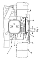
- a single cylinder engine 10 is shown including cylinder block 12, crankshaft 14, valve cover 16 and spark plug 18.
- Spark plug wire 20 supplies electrical ignition pulses to spark plug 18.
- Muffler 22 is shown at the lower right hand side of the engine connected to an exhaust manifold 24. The position of manifold 24 and muffler 22 may be reversed with respect to the engine as shown in the dotted line representations with manifold 24' and muffler 22' located toward the left of engine 10.
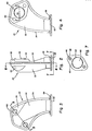
- manifold 24 comprises a shell housing including an upper shell half 30 and a lower shell half 32 which are secured and sealed together by means of a crimp seam 34 to form a chamber 35.
- the seal provided by crimp seam 34 between upper shell half 30 and lower shell half 32 insures that exhaust gas passing through manifold 24 will exit through the manifold outlet port.
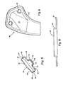
- Seam 34 as best seen in Fig. 5, comprises a flanged portion 36 of lower shell half 32 which is crimped around a flanged portion 38 of upper shell 30.
- a manifold inlet port 46 is provided in the lower shell of manifold 24 including an upstanding flanged portion 48.
- Flange 48 is disposed inside an engine exhaust port (not shown) in the cylinder block of engine 10 and manifold 24 is secured to the cylinder block by means of two bolts 56.
- Bolts 56 are disposed in mounting holes 50 in upper shell 30 and which are aligned with mounting holes 52 in lower shell 32 of the manifold.
- two bolts 56 are provided for securing the manifold to the cylinder block, although more or fewer such bolts and mounting holes may be provided.
- 3 and 5 T elieved portions 54 are provided in lower shell 32 for accommodating mounting holes 52 and fasteners 56.
- an outlet port 60 is provided in manifold 24, which port comprises an aperture in muffler mounting flange 62.
- Mounting flange 62 is welded to upper and lower shell halves 30 and 32, respectively, at 64.
- Muffler mounting flange 62 is secured to muffler 22 by means of two bolts 68 which are disposed in mounting holes 66 in muffler mounting flange 62.
- Mounting holes 66 each include an upstanding flange 69.
- a curved baffle or deflector 72 is disposed inside chamber 35 opposite inlet port 46.
- Baffle 72 is secured to lower housing shell 32 by means of spot welding or any other suitable means and is spaced apart from the inner wall of lower shell half 32 to form a dead air pocket 74 or chamber therewith.
- the depth of space 74 between baffle 72 and inner wall 78 is in the range of 3/16 inch to 5/16 inch.
- Dead air space 74 provides insulation for the manifold housing so that hot exhaust gas entering manifold inlet port 46 from the exhaust port of the engine cylinder will impinge directly on baffle 72 rather than on inner wall 78 of lower shell half 32.
- Baffle 72 is curved in order to deflect the entering hot gas in a smooth continuous fashion from inlet port 46 to outlet port 60 through an angle of substantially 90°.
- the temperature of the exhaust gas may be in the range of 1,100 to 1,200° F, whereby baffle 72 is heated to temperatures in that range during operation of the engine. Applicant has found that the temperature of the exhaust manifold housing will be as much as 180° F cooler than the temperature of the adjacent baffle 72 due to the insulation provided by space 74. As the exhaust gas passes from inlet port 46 of manifold 24 to outlet port 60 the temperature of the exhaust gas will decrease as heat is given up to the exhaust manifold. The temperature of baffle 72 will be highest at the point where the exhaust gas impinges directly on baffle 72 from inlet port 46.
- the entire manifold 24, including baffle 72, upper shell half 30 and lower shell half 32 are preferably constructed of common draw quality cold rolled steel stock which is easily manufactured into the desired shape since it has good drawing qualities.
- Muffler mounting flange 62 may be formed of the same material and is preferably spot welded to upper and lower manifold shells 30 and 32.
- baffle 72 is preferably spot welded to lower housing 32 to provide good contact therewith and to secure baffle 72 in place.
Landscapes
- Engineering & Computer Science (AREA)
- Chemical & Material Sciences (AREA)
- Combustion & Propulsion (AREA)
- Mechanical Engineering (AREA)
- General Engineering & Computer Science (AREA)
- Exhaust Silencers (AREA)
Applications Claiming Priority (2)
| Application Number | Priority Date | Filing Date | Title |
|---|---|---|---|
| US759644 | 1985-07-26 | ||
| US06/759,644 US4671057A (en) | 1985-07-26 | 1985-07-26 | Stamped exhaust manifold including a baffle for forming an insulated chamber |
Publications (2)
| Publication Number | Publication Date |
|---|---|
| EP0209657A1 true EP0209657A1 (fr) | 1987-01-28 |
| EP0209657B1 EP0209657B1 (fr) | 1989-04-26 |
Family
ID=25056423
Family Applications (1)
| Application Number | Title | Priority Date | Filing Date |
|---|---|---|---|
| EP86106423A Expired EP0209657B1 (fr) | 1985-07-26 | 1986-05-12 | Collecteur d'échappement estampé, comportant un déflecteur délimitant une chambre isolée |
Country Status (7)
| Country | Link |
|---|---|
| US (1) | US4671057A (fr) |
| EP (1) | EP0209657B1 (fr) |
| JP (1) | JPS6229712A (fr) |
| CA (1) | CA1272089A (fr) |
| DE (1) | DE3663060D1 (fr) |
| NZ (1) | NZ215687A (fr) |
| ZA (1) | ZA862604B (fr) |
Cited By (1)
| Publication number | Priority date | Publication date | Assignee | Title |
|---|---|---|---|---|
| EP0249339A3 (fr) * | 1986-06-13 | 1989-03-01 | Arvin Industries, Inc. | Collecteur d'échappement |
Families Citing this family (7)
| Publication number | Priority date | Publication date | Assignee | Title |
|---|---|---|---|---|
| US4928372A (en) * | 1989-04-07 | 1990-05-29 | Ap Parts Manufacturing Company | Process for manufacturing stamp formed mufflers |
| US4905636A (en) * | 1989-05-08 | 1990-03-06 | Tecumseh Products Company | Anti-puddling turbulence inducing cylinder head intake port and manifold |
| EP1041255A3 (fr) | 1999-04-01 | 2003-04-02 | Mascotech Tubular Products, Inc. | Collecteur d'échappement estampé pour moteurs de véhicule |
| US8356411B2 (en) * | 2008-04-07 | 2013-01-22 | Benteler Automotive Corporation | Exhaust manifold with hybrid construction and method |
| US8910470B2 (en) | 2013-05-17 | 2014-12-16 | Ford Global Technologies, Llc | Exhaust system having a flow rotation element and method for operation of an exhaust system |
| US9238992B2 (en) | 2013-05-17 | 2016-01-19 | Ford Global Technologies, Llc | Exhaust system having a flow rotation element and method for operation of an exhaust system |
| US10228160B2 (en) | 2014-09-30 | 2019-03-12 | Trane International Inc. | Furnace cabinet with integral protrusion |
Citations (4)
| Publication number | Priority date | Publication date | Assignee | Title |
|---|---|---|---|---|
| US3650354A (en) * | 1971-04-12 | 1972-03-21 | Briggs & Stratton Corp | Muffler for internal combustion engines |
| US3685613A (en) * | 1970-05-12 | 1972-08-22 | Victa Ltd | Mufflers for internal combustion engines |
| DE2340342A1 (de) * | 1973-08-09 | 1975-02-20 | Audi Nsu Auto Union Ag | Brennkraftmaschine mit einem reaktor zur nachverbrennung unverbrannter abgasbestandteile |
| US4022019A (en) * | 1970-11-20 | 1977-05-10 | Alfa Romeo S.P.A. | Exhaust conveying system for internal combustion engines |
Family Cites Families (11)
| Publication number | Priority date | Publication date | Assignee | Title |
|---|---|---|---|---|
| US1044181A (en) * | 1911-03-29 | 1912-11-12 | Guarantee Construction Company | Conveyer-elbow. |
| US2255807A (en) * | 1940-01-26 | 1941-09-16 | Carl H Plumlee | Desilting machine |
| US3043094A (en) * | 1960-02-29 | 1962-07-10 | Alco Products Inc | Exhaust manifolds |
| US3413803A (en) * | 1967-02-24 | 1968-12-03 | Du Pont | Exhaust manifold reaction system and apparatus |
| US3541785A (en) * | 1967-05-31 | 1970-11-24 | Daimler Benz Ag | Exhaust gas line connected to the cylinder heads of an internal combustion engine |
| JPS4844684B1 (fr) * | 1970-01-14 | 1973-12-26 | ||
| US3958418A (en) * | 1974-09-03 | 1976-05-25 | General Motors Corporation | Clamp arrangement |
| JPS5189915U (fr) * | 1975-01-16 | 1976-07-19 | ||
| JPS5247124A (en) * | 1975-10-13 | 1977-04-14 | Nissan Motor Co Ltd | Htemal reactor of engine for automobile |
| IT1188883B (it) * | 1979-09-06 | 1988-01-28 | Zeuna Staerker Kg | Collettore per motori alternativi a combustione interna |
| US4356885A (en) * | 1981-08-20 | 1982-11-02 | Dello Christy J | Chambered-core motorcycle-exhaust apparatus |
-
1985
- 1985-07-26 US US06/759,644 patent/US4671057A/en not_active Expired - Lifetime
-
1986
- 1986-04-03 NZ NZ215687A patent/NZ215687A/en unknown
- 1986-04-04 CA CA000505843A patent/CA1272089A/fr not_active Expired - Fee Related
- 1986-04-08 ZA ZA862604A patent/ZA862604B/xx unknown
- 1986-05-12 EP EP86106423A patent/EP0209657B1/fr not_active Expired
- 1986-05-12 DE DE8686106423T patent/DE3663060D1/de not_active Expired
- 1986-06-27 JP JP61149827A patent/JPS6229712A/ja active Granted
Patent Citations (4)
| Publication number | Priority date | Publication date | Assignee | Title |
|---|---|---|---|---|
| US3685613A (en) * | 1970-05-12 | 1972-08-22 | Victa Ltd | Mufflers for internal combustion engines |
| US4022019A (en) * | 1970-11-20 | 1977-05-10 | Alfa Romeo S.P.A. | Exhaust conveying system for internal combustion engines |
| US3650354A (en) * | 1971-04-12 | 1972-03-21 | Briggs & Stratton Corp | Muffler for internal combustion engines |
| DE2340342A1 (de) * | 1973-08-09 | 1975-02-20 | Audi Nsu Auto Union Ag | Brennkraftmaschine mit einem reaktor zur nachverbrennung unverbrannter abgasbestandteile |
Cited By (1)
| Publication number | Priority date | Publication date | Assignee | Title |
|---|---|---|---|---|
| EP0249339A3 (fr) * | 1986-06-13 | 1989-03-01 | Arvin Industries, Inc. | Collecteur d'échappement |
Also Published As
| Publication number | Publication date |
|---|---|
| CA1272089A (fr) | 1990-07-31 |
| DE3663060D1 (en) | 1989-06-01 |
| JPS6229712A (ja) | 1987-02-07 |
| ZA862604B (en) | 1986-11-26 |
| NZ215687A (en) | 1988-02-29 |
| EP0209657B1 (fr) | 1989-04-26 |
| US4671057A (en) | 1987-06-09 |
| JPH0219287B2 (fr) | 1990-05-01 |
Similar Documents
| Publication | Publication Date | Title |
|---|---|---|
| EP2456964B1 (fr) | Système de fixation pour un silencieux | |
| CA1056246A (fr) | Garniture d'orifices d'echappement de moteurs | |
| US8813716B2 (en) | Pre-combustion chamber tip | |
| US6789460B2 (en) | Multipart cooled piston for a combustion engine | |
| US4570585A (en) | Light metal cylinder head with valve seat insert | |
| US4671057A (en) | Stamped exhaust manifold including a baffle for forming an insulated chamber | |
| US20020180326A1 (en) | Spark plug of an internal combustion engine | |
| US3940927A (en) | Internal combustion engine having a reactor for afterburning of unburned exhaust gas constituents | |
| US4483140A (en) | Exhaust gas conduit system for multi-cylinder reciprocating piston internal combustion engines | |
| US6019081A (en) | Cooled pre-combustion chamber assembly | |
| CA1292116C (fr) | Procede de fabrication d'une tubulure d'echappement | |
| US5765373A (en) | Gas flow headers for internal combustion engines | |
| US8291880B2 (en) | Internal combustion engine comprising several combustion chambers | |
| US5729975A (en) | Semi-airgap manifold formation | |
| US20040182332A1 (en) | Liquid-cooled valve seat ring | |
| US6992426B2 (en) | Spark plug of an internal combustion engine | |
| US7272927B2 (en) | Air gap-insulated exhaust manifold for internal combustion engines | |
| US3942917A (en) | Housing for circular piston combustion engine of trochoid type and method of producing the same | |
| JPH05171932A (ja) | 排気マニホルドおよびその製造方法 | |
| US4050132A (en) | Method of producing a housing for circular piston combustion engine of trochoid type | |
| US3316888A (en) | Cylinder head construction | |
| US3892214A (en) | Cast-in E.F.E. hot plate | |
| JPH0141858Y2 (fr) | ||
| GB2172338A (en) | I.C. engine cylinder head exhaust passage inserts | |
| US11715932B2 (en) | Internal combustion engine spark plug and method of manufacturing the same |
Legal Events
| Date | Code | Title | Description |
|---|---|---|---|
| PUAI | Public reference made under article 153(3) epc to a published international application that has entered the european phase |
Free format text: ORIGINAL CODE: 0009012 |
|
| AK | Designated contracting states |
Kind code of ref document: A1 Designated state(s): DE FR GB IT |
|
| 17P | Request for examination filed |
Effective date: 19870119 |
|
| 17Q | First examination report despatched |
Effective date: 19871116 |
|
| GRAA | (expected) grant |
Free format text: ORIGINAL CODE: 0009210 |
|
| AK | Designated contracting states |
Kind code of ref document: B1 Designated state(s): DE FR GB IT |
|
| ITF | It: translation for a ep patent filed | ||
| REF | Corresponds to: |
Ref document number: 3663060 Country of ref document: DE Date of ref document: 19890601 |
|
| ET | Fr: translation filed | ||
| PLBE | No opposition filed within time limit |
Free format text: ORIGINAL CODE: 0009261 |
|
| STAA | Information on the status of an ep patent application or granted ep patent |
Free format text: STATUS: NO OPPOSITION FILED WITHIN TIME LIMIT |
|
| 26N | No opposition filed | ||
| ITTA | It: last paid annual fee | ||
| PGFP | Annual fee paid to national office [announced via postgrant information from national office to epo] |
Ref country code: GB Payment date: 20000410 Year of fee payment: 15 |
|
| PG25 | Lapsed in a contracting state [announced via postgrant information from national office to epo] |
Ref country code: GB Free format text: LAPSE BECAUSE OF NON-PAYMENT OF DUE FEES Effective date: 20010512 |
|
| GBPC | Gb: european patent ceased through non-payment of renewal fee |
Effective date: 20010512 |
|
| PGFP | Annual fee paid to national office [announced via postgrant information from national office to epo] |
Ref country code: FR Payment date: 20030423 Year of fee payment: 18 |
|
| PGFP | Annual fee paid to national office [announced via postgrant information from national office to epo] |
Ref country code: DE Payment date: 20030425 Year of fee payment: 18 |
|
| PG25 | Lapsed in a contracting state [announced via postgrant information from national office to epo] |
Ref country code: DE Free format text: LAPSE BECAUSE OF NON-PAYMENT OF DUE FEES Effective date: 20041201 |
|
| PG25 | Lapsed in a contracting state [announced via postgrant information from national office to epo] |
Ref country code: FR Free format text: LAPSE BECAUSE OF NON-PAYMENT OF DUE FEES Effective date: 20050131 |
|
| REG | Reference to a national code |
Ref country code: FR Ref legal event code: ST |
|
| PG25 | Lapsed in a contracting state [announced via postgrant information from national office to epo] |
Ref country code: IT Free format text: LAPSE BECAUSE OF NON-PAYMENT OF DUE FEES;WARNING: LAPSES OF ITALIAN PATENTS WITH EFFECTIVE DATE BEFORE 2007 MAY HAVE OCCURRED AT ANY TIME BEFORE 2007. THE CORRECT EFFECTIVE DATE MAY BE DIFFERENT FROM THE ONE RECORDED. Effective date: 20050512 |