EP0210585A2 - Dispositif de support et de réglage pour le siège et le dossier d'une chaise de travail - Google Patents
Dispositif de support et de réglage pour le siège et le dossier d'une chaise de travail Download PDFInfo
- Publication number
- EP0210585A2 EP0210585A2 EP86110108A EP86110108A EP0210585A2 EP 0210585 A2 EP0210585 A2 EP 0210585A2 EP 86110108 A EP86110108 A EP 86110108A EP 86110108 A EP86110108 A EP 86110108A EP 0210585 A2 EP0210585 A2 EP 0210585A2
- Authority
- EP
- European Patent Office
- Prior art keywords
- support
- seat
- coupling
- backrest
- axis
- Prior art date
- Legal status (The legal status is an assumption and is not a legal conclusion. Google has not performed a legal analysis and makes no representation as to the accuracy of the status listed.)
- Granted
Links
Images

Classifications
-
- A—HUMAN NECESSITIES
- A47—FURNITURE; DOMESTIC ARTICLES OR APPLIANCES; COFFEE MILLS; SPICE MILLS; SUCTION CLEANERS IN GENERAL
- A47C—CHAIRS; SOFAS; BEDS
- A47C1/00—Chairs adapted for special purposes
- A47C1/02—Reclining or easy chairs
- A47C1/031—Reclining or easy chairs having coupled concurrently adjustable supporting parts
- A47C1/032—Reclining or easy chairs having coupled concurrently adjustable supporting parts the parts being movably-coupled seat and back-rest
- A47C1/03205—Reclining or easy chairs having coupled concurrently adjustable supporting parts the parts being movably-coupled seat and back-rest having adjustable and lockable inclination
- A47C1/03222—Reclining or easy chairs having coupled concurrently adjustable supporting parts the parts being movably-coupled seat and back-rest having adjustable and lockable inclination by means of screw-and-nut mechanism
-
- A—HUMAN NECESSITIES
- A47—FURNITURE; DOMESTIC ARTICLES OR APPLIANCES; COFFEE MILLS; SPICE MILLS; SUCTION CLEANERS IN GENERAL
- A47C—CHAIRS; SOFAS; BEDS
- A47C1/00—Chairs adapted for special purposes
- A47C1/02—Reclining or easy chairs
- A47C1/031—Reclining or easy chairs having coupled concurrently adjustable supporting parts
- A47C1/032—Reclining or easy chairs having coupled concurrently adjustable supporting parts the parts being movably-coupled seat and back-rest
- A47C1/03255—Reclining or easy chairs having coupled concurrently adjustable supporting parts the parts being movably-coupled seat and back-rest with a central column, e.g. rocking office chairs
-
- A—HUMAN NECESSITIES
- A47—FURNITURE; DOMESTIC ARTICLES OR APPLIANCES; COFFEE MILLS; SPICE MILLS; SUCTION CLEANERS IN GENERAL
- A47C—CHAIRS; SOFAS; BEDS
- A47C1/00—Chairs adapted for special purposes
- A47C1/02—Reclining or easy chairs
- A47C1/031—Reclining or easy chairs having coupled concurrently adjustable supporting parts
- A47C1/032—Reclining or easy chairs having coupled concurrently adjustable supporting parts the parts being movably-coupled seat and back-rest
- A47C1/03294—Reclining or easy chairs having coupled concurrently adjustable supporting parts the parts being movably-coupled seat and back-rest slidingly movable in the base frame, e.g. by rollers
Definitions
- the invention relates to a support and adjustment device for seat and backrest on a work chair with a support part connected to the feet and at least partially articulated seat support and backrest support, the support part, seat support and backrest support being symmetrical on both sides of the longitudinal center plane of the work chair and provided with articulated holes , have at least partially overlapping support and connecting flanges which are connected to one another, possibly via coupling links, by means of articulated axis rods.
- the invention serves this basic need.
- it should also enable the subsequent retrofitting of chairs, so that, on the one hand, chairs may be produced in stock, but may be requested differently from the manufacturer at short notice Middlemen can be quickly converted and on the other hand, it should give the customer, who may possibly buy a larger number of similar chairs together, the opportunity to convert the already existing chairs for a different adjustment option or a different movement sequence if individual z . B. proves necessary from the special working conditions or physical circumstances of a user.
- the invention has for its object to provide support and adjustment devices for the seat and backrest of a work chair with the features mentioned above that on the one hand the essential components of chairs with different kinematics are made the same or similar, but with some. different connecting means can be assembled.
- articulated axes or articulated holes are provided for the optional combination of adjusting devices for the seat and / or backrest that operate with different articulated polygonal kinematics, and two coupling levers that can be used and have at least two articulated holes located at the same locations are provided , of which the respective one is articulated at least on the support part and on the backrest support.
- the invention therefore takes a multi-part approach. It contains the necessary main components that are common to several kinematic systems. For this, the kinematics plan is optimized and articulation points are selected, which are favorable or at least tolerable for the various adjustment needs, and the different needs are satisfied by the selection of specific articulation points and by the use of intermediate parts. Since such movement devices require coupling elements in addition to rigid parts and main parts, the invention has the advantageous way of providing a coupling lever, but providing this in various configurations, so that the different kinematics requirements can be met by exchanging or optionally using slightly different coupling levers and corresponding articulation. The coupling levers naturally have to meet the various articulation points and lever lengths in the basic kinematics plan.
- the coupling lever is an essential part of enabling the exchange and creating different setting and movement options.
- the coupling lever is designed as an elongated lever with three articulated holes. He is then usually about flat under the seat and is articulated on the seat and backrest and possibly the seat support common axis, namely the seat-back axis approximately in the middle.
- the middle articulated hole is provided on the elongated coupling lever a little above the connecting line of the two articulated holes on the outside.
- the seat linkage in the rear area can then be set relatively high, which is favorable for the adjustment and coupling movement, while the other two axes lie somewhat lower in the mechanics.
- a coupling lever is expediently provided in a different embodiment as an angle lever with three articulated holes which form approximately a right-angled triangle. These two levers can then be exchanged for each other and thus enable a variety of different chair mechanics. Other variants of coupling levers are also possible.
- the coupling levers can basically be constructed in many different forms. Since the widest possible support base is required due to the expansion in width and the support of large forces, even when the seat surface is subjected to a corner load, such bases become Chair mechanics are usually symmetrical to the central longitudinal plane. In principle, pairs of elements can also be provided, including pairs of coupling levers, which, however, are treated as a lever in this description because of the only schematic explanation of the kinematics plan. However, it is particularly expedient if the coupling levers are formed as an approximately U-shaped component in profile with two legs having the articulated holes. They are then automatically tilt-free and offer a broad basis for supporting the forces and for supporting axles to be inserted, on which adjustment elements or the like can act.
- the support part, seat part and backrest support are each folded and / or welded together with parallel flat walls as a cast part or forged part or preferably as a sheet metal part.
- this is not specifically dealt with in the description because such components have long been known for individual chair mechanics.
- the backrest support has an articulated hole in its front upper region, which in the kinematic plan of all support and adjustment devices to be formed with optionally interchangeable polygonal elements is always at the same location, namely at the location the seat-back axis is located, and connects the backrest support, the coupling lever and the support part or a coupling provided between the support part and the seat-back axis via an articulated axis rod.
- a sliding joint can be provided on the support part in front of the common joint axis - seat-back axis - to which the joint axis rod penetrating the front joint hole of the coupling lever engages.
- support can be provided via an axis rod.
- a length-adjustable coupling In order to enable the desired movements and couplings, a length-adjustable coupling must be provided depending on the desired chair mechanics. This allows favorable power support and force introduction, locking devices and the like.
- a so-called lockable gas spring i.e. piston-cylinder unit with gas-filled spaces, possibly used coil springs, hydraulic circulating fluids, valves and the like. It is used in many places in such chair mechanics.
- variable-length coupling between the support part and an axis in the same place in the overall kinematics plan - coupling axis - which is provided with the backrest support or at the same time with the backrest support and the lower articulation point of the coupling lever designed as an angle lever, variable-length coupling.
- This coupling is thus between the backrest and support member before - provided preferably at the bottom and also the angle lever can attack when it leaves the respective desired kinematics appear appropriate.
- the variable-length coupling can have a spring. A spring-loaded coupling of the movement of the seat and backrest can then be achieved with simple means.
- the variable-length coupling can have a lock.
- variable-length coupling can be a lockable gas spring.
- a lockable gas spring Such a component has favorable damping properties and, above all, all elements for adjustment, damping and locking in a commercially available component.
- the seat can be provided fixed or articulated so that it can perform inclination movements about an axis parallel to the front edge of the seat or coupled movements with the backrest.
- a length-changeable seat head is provided which is designed as a seat support or is firmly connected to it.
- the rear hinge point can then be raised or lowered by suitable means.
- the backrest can also be articulated and moved with it or coupled in some other way. It is expedient if the front joint axis between the support part and the seat coupling is placed far forward in the vicinity of the front edge area of the seat.
- the support part and seat support are expediently firmly connected to one another or formed from a single component. Then, however, parts of the overall kinematics plan and the articulated holes and components available therefor can be used for a backrest adjustment, without the need for separate components, separate machining, tools and the like.
- An advantageous design concept for the adjustment of inclinations or initial inclinations between the seat and backrest and the support part can expediently provide that between the rear articulated axis - adjusting axis - the elongated coupling lever and one at a distance from the seat-back axis between the backrest support and the support part or seat support- Coupling and coupling lever lying point of attack - support plate - a variable-length adjusting member is provided, which serves to adjust the inclination of the backrest and / or seat support.
- the adjustability has been placed at a convenient location in the lower region of the backrest support with simple means.
- the adjusting element can advantageously be a screw equipped with a handwheel which engages in a threaded joint rod which is articulated in the rear joint hole of the elongated coupling lever.
- Such an embodiment known per se is simple and reliable, but it can be incorporated particularly well into the overall kinematics plan here because the screwing movement acts on an axis which can be placed in an exchangeable manner at a corresponding articulation point.
- the counter bearing can also be a drilled joint rod with a corresponding articulation in the back support or a flat wall with an elongated hole and corresponding disk support for the spindle.
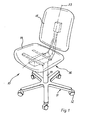
- a work chair 10 has a five-arm base 11 with casters 12 and a preferably height-adjustable column 13, a seat 14 and a backrest 15 and a support and adjustment device 16 for the seat and backrest, which, as is generally customary in practice, is also known as a "chair mechanism ", and which is described in detail below.
- the support and adjustment device 16 has a support part 17 firmly connected to the column 13, a seat support 18 and a backrest support 19 as well as a coupling lever 20.1 or in another embodiment 20.2. Furthermore, a variable-length coupling 21 and an adjusting spindle 22 can be provided, as is partly the case. is the case for the example of FIGS. 2 to 4.
- the support part 17, seat support 18 and backrest support 19 have symmetrically running support and connecting flanges which run vertically on both sides of the longitudinal center plane 23 of the work chair and are provided with joint holes and at least partially overlapping. These are connected to one another, possibly via coupling links, by means of articulated axis rods. This can be seen from FIGS. 2 to 4 and will now be explained.
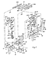
- the support part flanges 17.1 and 17.2 can be seen in FIG. 2. They are firmly connected to the column 13 via cross connections, not shown. These are preferably punched and folded sheet metal parts, for example 3 mm thick, which are welded together with connecting means, possibly welded, the support part flanges 17.1 and 17.2 being approximately 100 mm apart.
- the seat support 18 has seat support flanges 18.1 and 18.2, which are also vertical and have a distance of slightly more than 100 mm, so that they are outside the support part flanges 17.1 and 17.2. As can be seen from FIG. 2, they are connected by means of seat support angles 18.3 and 18.4 and a U-shaped seat support bridge 18.5, for example by welding. The seat is placed as shown in Fig. 3 and 4 and fastened with suitable fasteners.
- the backrest support 19 has backrest support flanges 19.1 and 19.2 which are at a distance of somewhat less than 100 mm, so that they lie within the support part flanges 17.1, 17.2 and the seat support flanges 18.1 and 18.2.
- the exploded view of FIG. 2 illustrates with the help of which axes the parts which are plugged into one another are to be connected.
- the backrest support 19 has a connecting web 19.3 on which a backrest support rod 19.4 for a preferably height-adjustable backrest 15 is attached.
- the backrest support 19 also has in the lower region - as can be seen from FIGS. 2 and 3 - a transverse support plate 19.5, which has an elongated hole 24.
- the elongated hole 24 can be penetrated by the adjusting spindle 22, which is then supported on both sides with the aid of the support disks 22.2 on the support plate 19.5.
- the coupling levers 20 have coupling flanges 20.3 and 20.4 or 20.5 and 20.6 located at a distance of approximately 35 mm from one another, which are connected to one another via webs, so that there are U-shaped components in profile, which are also punched out and angled parts of about two up to three mm wall thickness can be formed, but can also be formed as cast or forged parts.
- the two coupling levers 20.1 and 20.2 differ only in the profile of the coupling flanges.
- the coupling flanges 20.3 and 20.4 are designed as flat, elongated levers with three joint holes 20.71, 20.72 and 20.73.
- the middle hinge hole 20.72 lies somewhat above the connection of the two hinge holes 20.71 and 20.73 lying in the region of the ends, as can be seen from the left and FIG. 3 in FIG. 2.
- the coupling flanges 20.5 and 20.6 are - as can be seen from FIG. 2 on the right and FIG. 4 - designed as an angle lever with an arrangement of three hinge axes on an approximately right-angled triangle, the hinge holes 20.71 and 20.72 being in the same places, while the hinge hole 20.74 is formed on the lower articulated lever part 20.8.
- a web area 20.9 can be seen here on the right in FIG. 2.
- an actuating axis is provided which is inserted into the rear joint hole 20.73 of the elongated coupling lever and has a length which is slightly larger than the width of the coupling lever 20.1. It has a threaded hole 25.1 in which the external thread 22.1 of the adjusting spindle 22 fits.
- the adjusting spindle 22 has a handwheel 22.3 at its other end.
- the variable-length coupling 21 is a so-called gas spring.
- This is a piston-cylinder unit, the cylinder 21.1 of which is connected in a suitable manner, for example by screwing into a threaded hole, to a round rod referred to as spring axle rod 26.
- a piston rod 21.2 which has a piston rod head 21.3 with an articulated hole.
- a piston is provided inside.
- Piston chambers are filled with oil.
- valves, gas chambers and actuating means in particular in the form of a pin to be inserted from the front, so that the piston rod 21.2 can dip against spring force with a corresponding release of the locking mechanism and automatically exit if there is no counterforce.
- Such a gas spring is widely used for chair mechanics.
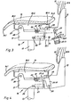
- the front seat axle 27 is relatively far forward to the front edge 14.1 of the seat, so that this front area does not rise too much when pivoting and lowers.
- the support part flanges 17.1 and 17.2 have in this.
- the seat support 18 is shown here somewhat schematically as a seat support coupling 18.6 compared to FIG. 2.
- the seat-back axis 29 is formed in the seat support.
- it is a seat-back axis 29 which is movable in space and which can essentially pivot up and down about the seat front axis 27 on a circular arc corresponding to the length of the seat support dome 18.6. This pivoting is determined by the joint polygon discussed in the following.
- the variable-length coupling 21 is provided.
- the coupling axis 30 lies at a distance corresponding approximately to the height of the mechanics, almost exactly below the seat-back axis 29, but slightly shifted to the rear in the starting position of the kinematics plan. It lies approximately in the front lower corner area of the backrest support 19 and thus creates an essentially vertical articulated arm between the seat-back axis 29 and the coupling axis 30.
- the length-adjustable coupling 21 lies approximately parallel to the seat support coupling 18.6, so that it acts as a spring axis 26 designated, fixed axis is approximately in the region of the connection to the column 13, as the figures illustrate.
- the spring axis 26 and the respective length of the variable-length coupling 21 thus determine the kinematic possibilities for the movement of the seat-back axis 29 and thus of the seat and backrest, which are coupled to one another in these exemplary embodiments. Without further support however the arrangement will drop down. Therefore, the coupling lever 20 is provided for further support and determination of the movement of the seat-back axis 29.
- the sliding joint 32 is now formed in the support part 17 in the form of aligned slots 32.1 and 32.2. For example, oblong-hole plastic parts are inserted there, each having an opening which corresponds to the thickness of the inserted articulated rod and the length of the desired movement.
- This sliding joint 32 is slightly offset from the center to the rear, so that there is a very flat articulated arm on the coupling lever 20, namely between the seat-back axis 29 and the sliding axis 31. Since the coupling lever 20 is articulated in a suitable manner on the seat support 18, the length of the variable-length coupling 21 now determines the exact position of the seat-back axis 29 in the part of the kinematics plan previously considered. If the length of the coupling 21 is reduced, see above the seat-back axis 29 lowers and the sliding axis 31 pushes slightly forward in the sliding joint 32. If the coupling 21 is lengthened, the seat-back axis 29 lifts and the sliding axis 31 moves slightly to the rear in the sliding joint 32.
- one has a stable system with which one can determine the inclination of the seat 14 by lengthening and shortening the coupling 21.
- the backrest 15 also moves in accordance with the selected connection. If you always want a uniform pivoting of the backrest together with the seat without adjustable change in the relative position of the two to one another, then choose the angle coupling lever 20.2 according to FIG. 2 on the right or FIG. 4. This is with its articulated hole 20.74 also attached to the coupling axis 30.
- the backrest is rigidly connected to the coupling lever 20.2 and follows all its movements.
- the backrest then executes a small inclination movement relative to the seat 14 according to the lever movements which are evident, which is determined by the lever lengths and the position of the articulation points, but cannot be adjusted.
- the same movement can be obtained if you also want a relative adjustment between the backrest and its linkage.
- the elongated coupling lever 20.1 is used, as can be seen from FIG. 2 on the left and FIG. 3.
- the spindle 22 is then rotatable, but not axially displaceable, fastened to the backrest support 19 on the support plate 19.5 and screwed into the adjusting shaft 25 inserted through the articulated holes 20.73.
- the bearing of the spindle 22 is at a distance from the seat-back axis 29, so that there is an articulated triangle with sliding joint.
- articulated axis rods can be simple round axis rods cut to length.
- the bearing elements used are suitably equipped with collars and holders bearing shell parts, preferably made of suitable low-friction, durable plastics.
- the articulated axis rods are held in their position with suitable means, spacer sleeves and clamping rings, whereby the relative position can also be easily guaranteed for all parts with regard to the orientation to the central axis.
- Tubes can also be provided on individual joint rods, in particular for the coupling lever, so that it can be held in its central position.
- FIGS. 5 and 6 uses axes, coupling levers and backrest supports of the previous exemplary embodiments in order to implement a simpler chair mechanism.
- the support part and seat support are combined to form a single component, which is referred to as seat support 35 and has support flanges 35.1 and 35.2 on which the seat supports 35.3 and 35.4 are fastened, for example welded on.
- the seat 14 lies thereon.
- the connection to the column 13 is implemented in the usual way by a transverse wall or the like.
- the support flanges 35.1 and 35.2 have eyes 35.5 and 35.6, in which the seat-back axis 29 is inserted in corresponding joint holes.
- the backrest support 19 is constructed, as in the previous example, and corresponds completely to the illustration in FIG. 2 on the left and in FIG. However, it is not used here as a sliding joint, but only as a support.
- the elongated coupling lever 20.1 is used in the manner previously discussed and is connected to the backrest support 19 via the adjusting spindle 22 and the actuating axis 25 and the support plate 19.5. As can be seen, these two components and the positions of the articulation points are chosen the same, so that the same components can be mass-produced and used for simple chair mechanics.
- the mechanism only serves to support the backrest 15, which can be adjusted in inclination.
- the sliding axis 31 is here only a support axis which provides a fixed, non-pivoting connection between the seat support 35 and the coupling lever 20.1 causes.
Landscapes
- Health & Medical Sciences (AREA)
- Dentistry (AREA)
- General Health & Medical Sciences (AREA)
- Chairs For Special Purposes, Such As Reclining Chairs (AREA)
- Chairs Characterized By Structure (AREA)
- Chair Legs, Seat Parts, And Backrests (AREA)
Priority Applications (1)
| Application Number | Priority Date | Filing Date | Title |
|---|---|---|---|
| AT86110108T ATE72387T1 (de) | 1985-08-02 | 1986-07-23 | Stuetz- und verstelleinrichtung fuer sitz und rueckenlehne an einem arbeitsstuhl. |
Applications Claiming Priority (2)
| Application Number | Priority Date | Filing Date | Title |
|---|---|---|---|
| DE19853527785 DE3527785A1 (de) | 1985-08-02 | 1985-08-02 | Stuetz- und verstelleinrichtung fuer sitz und rueckenlehne an einem arbeitsstuhl |
| DE3527785 | 1985-08-02 |
Publications (3)
| Publication Number | Publication Date |
|---|---|
| EP0210585A2 true EP0210585A2 (fr) | 1987-02-04 |
| EP0210585A3 EP0210585A3 (en) | 1987-10-28 |
| EP0210585B1 EP0210585B1 (fr) | 1992-02-05 |
Family
ID=6277531
Family Applications (1)
| Application Number | Title | Priority Date | Filing Date |
|---|---|---|---|
| EP86110108A Expired - Lifetime EP0210585B1 (fr) | 1985-08-02 | 1986-07-23 | Dispositif de support et de réglage pour le siège et le dossier d'une chaise de travail |
Country Status (5)
| Country | Link |
|---|---|
| US (1) | US4718725A (fr) |
| EP (1) | EP0210585B1 (fr) |
| AT (1) | ATE72387T1 (fr) |
| AU (1) | AU598473B2 (fr) |
| DE (2) | DE3527785A1 (fr) |
Families Citing this family (11)
| Publication number | Priority date | Publication date | Assignee | Title |
|---|---|---|---|---|
| CH670363A5 (fr) * | 1986-09-24 | 1989-06-15 | Giroflex Entwicklungs Ag | |
| DE3930983C2 (de) * | 1989-09-16 | 1993-09-30 | Rolf Voelkle | Sitzmöbel mit neigungsverstellbarer Sitzfläche |
| ATE128612T1 (de) * | 1990-02-28 | 1995-10-15 | Svein Asbjornsen & Jan Lade A | Verstellbarer stuhl. |
| US5066069A (en) * | 1990-05-03 | 1991-11-19 | Systems Furniture Company | Chair back and seat adjustment mechanism |
| US5318345A (en) * | 1991-06-07 | 1994-06-07 | Hon Industries, Inc. | Tilt back chair and control |
| US5356200A (en) * | 1992-10-23 | 1994-10-18 | Doerner Products Ltd. | Unitary brake for a chair tilt mechanism |
| US9713381B2 (en) * | 2015-06-11 | 2017-07-25 | Davis Furniture Industries, Inc. | Chair |
| CN105105539A (zh) * | 2015-07-31 | 2015-12-02 | 韩玉生 | 一种多用途椅子 |
| JP6796991B2 (ja) * | 2016-10-20 | 2020-12-09 | 日本発條株式会社 | 振動減衰装置、及びこの振動減衰装置が設けられた車両用シート |
| US11589678B2 (en) | 2019-01-17 | 2023-02-28 | Hni Technologies Inc. | Chairs including flexible frames |
| US11197548B2 (en) * | 2019-12-16 | 2021-12-14 | Allseating Corporation | Reclining control system for a chair |
Family Cites Families (14)
| Publication number | Priority date | Publication date | Assignee | Title |
|---|---|---|---|---|
| US2650646A (en) * | 1949-08-23 | 1953-09-01 | Bassick Co | Resiliently mounted tiltable seat and back rest |
| GB724329A (en) * | 1952-04-25 | 1955-02-16 | Albert Ducrot | Improvements in or relating to convertible chairs |
| US2859799A (en) * | 1956-05-03 | 1958-11-11 | Edwin R Moore | Functional posture controller for chairs |
| CH524982A (de) * | 1970-05-20 | 1972-07-15 | Stella Werke Ag | Arbeitsstuhl |
| US3837704A (en) * | 1973-06-21 | 1974-09-24 | F Bauer | Seating furniture |
| US4143910A (en) * | 1977-09-12 | 1979-03-13 | Klaus Geffers | Chair having synchronously coupled tiltable seat and back rest |
| CH636252A5 (de) * | 1978-10-20 | 1983-05-31 | Syntech Sa | Ergonomischer stuhl. |
| DE2915368A1 (de) * | 1979-04-14 | 1980-10-30 | Link Wilhelm Kg | Buerostuhl |
| DE2925520A1 (de) * | 1979-06-25 | 1981-01-15 | Mauser Waldeck Gmbh | Drehsessel |
| IT7907016U1 (it) * | 1979-07-03 | 1981-01-03 | Co Fe Mo Di Moreschi Sergio E Claudio | Poltrona con sedile e schienale a posizioni regolabili con l'ausilio di cilindri a gas. |
| CH645795A5 (en) * | 1979-07-23 | 1984-10-31 | Drabert Soehne | Chair, in particular visual display unit chair |
| GB2125284B (en) * | 1982-08-16 | 1985-08-07 | Metalstand Co | Adjustable chairs |
| EP0114600B1 (fr) * | 1983-01-21 | 1986-08-27 | Pierre Schmitz | Chaise, notamment chaise de bureau |
| DE3316533A1 (de) * | 1983-05-06 | 1984-11-08 | Provenda Marketing AG, Herisau | Arbeitsstuhl, insbesondere buerostuhl |
-
1985
- 1985-08-02 DE DE19853527785 patent/DE3527785A1/de not_active Withdrawn
-
1986
- 1986-07-23 AT AT86110108T patent/ATE72387T1/de not_active IP Right Cessation
- 1986-07-23 DE DE8686110108T patent/DE3683809D1/de not_active Expired - Fee Related
- 1986-07-23 EP EP86110108A patent/EP0210585B1/fr not_active Expired - Lifetime
- 1986-07-25 US US06/890,768 patent/US4718725A/en not_active Expired - Fee Related
- 1986-07-28 AU AU60634/86A patent/AU598473B2/en not_active Ceased
Also Published As
| Publication number | Publication date |
|---|---|
| EP0210585A3 (en) | 1987-10-28 |
| EP0210585B1 (fr) | 1992-02-05 |
| AU6063486A (en) | 1987-02-05 |
| DE3527785A1 (de) | 1987-02-12 |
| ATE72387T1 (de) | 1992-02-15 |
| AU598473B2 (en) | 1990-06-28 |
| DE3683809D1 (de) | 1992-03-19 |
| US4718725A (en) | 1988-01-12 |
Similar Documents
| Publication | Publication Date | Title |
|---|---|---|
| DE2940250C2 (de) | Stuhl | |
| EP1358821B1 (fr) | Chaise avec un accumulateur d'energie dépendant du poids d'utilisateur | |
| DE19830418B4 (de) | Stuhlanordnung | |
| DE2545991B2 (de) | Stuhl mit schwenkbarem Rückenlehnenrahmen | |
| EP0210585B1 (fr) | Dispositif de support et de réglage pour le siège et le dossier d'une chaise de travail | |
| EP0198056B1 (fr) | Support de siege pour chaises, surtout pour des chaises de travail | |
| EP3528664B1 (fr) | Dispositif de mécanisme synchrone et chaise en étant équipée | |
| DE3124767A1 (de) | Rahmengeruest fuer einen stuhl | |
| EP4482358B1 (fr) | Accessoire fonctionnel motorisé pour sommier de lit à sommier tapissier ou de lit plateforme, ou pour sommier à lattes | |
| DE69607859T2 (de) | Verstellvorrichtung für die neigung einer rückenstütze bezüglich eines sitzteils bei stühlen | |
| DE102011051966B4 (de) | Stuhl | |
| DE19753465C2 (de) | Aktiv-dynamische, selbstrückstellende Sitzvorrichtung | |
| DE69714910T2 (de) | Verstellvorrichtung | |
| DE202022106177U1 (de) | Motorisierter Funktionsbeschlag für ein Bettgestell eines Plattformbetts oder für einen gerahmten Lattenrost | |
| DE9210254U1 (de) | Fußstütze | |
| DE69507725T2 (de) | Stuhl mit einem unterstütztem Lenkgetriebe | |
| AT404224B (de) | Liegefläche für ein bett | |
| DE8805510U1 (de) | Sitzschalen-Fahrwerk, insbesondere für Körperbehinderte | |
| DE29813944U1 (de) | Rahmen für ein Liegemöbel | |
| DE3447376A1 (de) | Moebel-traggestell | |
| DE19912830A1 (de) | Hebestuhl für Behinderte und Invalide | |
| DE69700227T2 (de) | Faltbare Struktur | |
| DE102022104284A1 (de) | Motorisierter Funktionsbeschlag für ein Bettgestell eines Boxspringbetts | |
| DE3619928A1 (de) | Funktions-sitzmoebel | |
| DE3429356A1 (de) | Beschlag fuer moebel |
Legal Events
| Date | Code | Title | Description |
|---|---|---|---|
| PUAI | Public reference made under article 153(3) epc to a published international application that has entered the european phase |
Free format text: ORIGINAL CODE: 0009012 |
|
| AK | Designated contracting states |
Kind code of ref document: A2 Designated state(s): AT BE CH DE FR GB IT LI LU NL SE |
|
| PUAL | Search report despatched |
Free format text: ORIGINAL CODE: 0009013 |
|
| AK | Designated contracting states |
Kind code of ref document: A3 Designated state(s): AT BE CH DE FR GB IT LI LU NL SE |
|
| 17P | Request for examination filed |
Effective date: 19871223 |
|
| 17Q | First examination report despatched |
Effective date: 19890309 |
|
| GRAA | (expected) grant |
Free format text: ORIGINAL CODE: 0009210 |
|
| AK | Designated contracting states |
Kind code of ref document: B1 Designated state(s): AT BE CH DE FR GB IT LI LU NL SE |
|
| PG25 | Lapsed in a contracting state [announced via postgrant information from national office to epo] |
Ref country code: SE Effective date: 19920205 Ref country code: NL Effective date: 19920205 Ref country code: GB Effective date: 19920205 Ref country code: FR Effective date: 19920205 Ref country code: BE Effective date: 19920205 |
|
| REF | Corresponds to: |
Ref document number: 72387 Country of ref document: AT Date of ref document: 19920215 Kind code of ref document: T |
|
| REF | Corresponds to: |
Ref document number: 3683809 Country of ref document: DE Date of ref document: 19920319 |
|
| ITF | It: translation for a ep patent filed | ||
| EN | Fr: translation not filed | ||
| NLV1 | Nl: lapsed or annulled due to failure to fulfill the requirements of art. 29p and 29m of the patents act | ||
| PG25 | Lapsed in a contracting state [announced via postgrant information from national office to epo] |
Ref country code: AT Effective date: 19920723 |
|
| PG25 | Lapsed in a contracting state [announced via postgrant information from national office to epo] |
Ref country code: LU Free format text: LAPSE BECAUSE OF NON-PAYMENT OF DUE FEES Effective date: 19920731 |
|
| GBV | Gb: ep patent (uk) treated as always having been void in accordance with gb section 77(7)/1977 [no translation filed] | ||
| PLBE | No opposition filed within time limit |
Free format text: ORIGINAL CODE: 0009261 |
|
| STAA | Information on the status of an ep patent application or granted ep patent |
Free format text: STATUS: NO OPPOSITION FILED WITHIN TIME LIMIT |
|
| 26N | No opposition filed | ||
| ITTA | It: last paid annual fee | ||
| PGFP | Annual fee paid to national office [announced via postgrant information from national office to epo] |
Ref country code: DE Payment date: 19930928 Year of fee payment: 8 |
|
| PGFP | Annual fee paid to national office [announced via postgrant information from national office to epo] |
Ref country code: CH Payment date: 19930929 Year of fee payment: 8 |
|
| PG25 | Lapsed in a contracting state [announced via postgrant information from national office to epo] |
Ref country code: LI Effective date: 19940731 Ref country code: CH Effective date: 19940731 |
|
| REG | Reference to a national code |
Ref country code: CH Ref legal event code: PL |
|
| PG25 | Lapsed in a contracting state [announced via postgrant information from national office to epo] |
Ref country code: DE Effective date: 19950401 |
|
| PG25 | Lapsed in a contracting state [announced via postgrant information from national office to epo] |
Ref country code: IT Free format text: LAPSE BECAUSE OF NON-PAYMENT OF DUE FEES;WARNING: LAPSES OF ITALIAN PATENTS WITH EFFECTIVE DATE BEFORE 2007 MAY HAVE OCCURRED AT ANY TIME BEFORE 2007. THE CORRECT EFFECTIVE DATE MAY BE DIFFERENT FROM THE ONE RECORDED. Effective date: 20050723 |