EP0210662B1 - Einrichtung zum Zuführen von Bauteilen - Google Patents
Einrichtung zum Zuführen von Bauteilen Download PDFInfo
- Publication number
- EP0210662B1 EP0210662B1 EP19860110630 EP86110630A EP0210662B1 EP 0210662 B1 EP0210662 B1 EP 0210662B1 EP 19860110630 EP19860110630 EP 19860110630 EP 86110630 A EP86110630 A EP 86110630A EP 0210662 B1 EP0210662 B1 EP 0210662B1
- Authority
- EP
- European Patent Office
- Prior art keywords
- magazine
- unit
- parts feeder
- feeder according
- parts
- Prior art date
- Legal status (The legal status is an assumption and is not a legal conclusion. Google has not performed a legal analysis and makes no representation as to the accuracy of the status listed.)
- Expired - Lifetime
Links
- 238000003780 insertion Methods 0.000 claims description 10
- 230000037431 insertion Effects 0.000 claims description 10
- 230000005484 gravity Effects 0.000 claims description 3
- 239000012530 fluid Substances 0.000 description 17
- 238000003491 array Methods 0.000 description 2
- 230000001419 dependent effect Effects 0.000 description 2
- 238000000034 method Methods 0.000 description 1
- 230000003287 optical effect Effects 0.000 description 1
- 239000011295 pitch Substances 0.000 description 1
- 229920003023 plastic Polymers 0.000 description 1
- 239000004033 plastic Substances 0.000 description 1
- 230000000717 retained effect Effects 0.000 description 1
Images



Classifications
-
- H—ELECTRICITY
- H05—ELECTRIC TECHNIQUES NOT OTHERWISE PROVIDED FOR
- H05K—PRINTED CIRCUITS; CASINGS OR CONSTRUCTIONAL DETAILS OF ELECTRIC APPARATUS; MANUFACTURE OF ASSEMBLAGES OF ELECTRICAL COMPONENTS
- H05K13/00—Apparatus or processes specially adapted for manufacturing or adjusting assemblages of electric components
- H05K13/02—Feeding of components
-
- H—ELECTRICITY
- H05—ELECTRIC TECHNIQUES NOT OTHERWISE PROVIDED FOR
- H05K—PRINTED CIRCUITS; CASINGS OR CONSTRUCTIONAL DETAILS OF ELECTRIC APPARATUS; MANUFACTURE OF ASSEMBLAGES OF ELECTRICAL COMPONENTS
- H05K13/00—Apparatus or processes specially adapted for manufacturing or adjusting assemblages of electric components
- H05K13/0084—Containers and magazines for components, e.g. tube-like magazines
Definitions
- the present invention relates to a parts feeder according to the preamble of claims 1 and 19.
- This apparatus comprises a part supply section, where magazines containing electric parts are arranged in rows and columns, and a magazine delivery mechanism.
- the apparatus further comprises an insertion section for supplying said electric parts from each column to a predeterminate position on a printed circuit board.
- the prepared magazines are placed in a stock case inclined at a necessary angle to allow magazines to fall by gravity.
- this object is accomplished by a parts feeder, in which the supply unit includes a plurality of devices arranged side by side and each having supporting means for supporting a magazine removed from one of the magazine units and holding means for holding the array of parts discharged from said magazine, wherin said supply unit is movable in a first direction transverse to a second direction in which said devices are arranged side by side.
- the parts feeder further comprises an escape unit for removing one magazine at a time from one of said magazine units and transferring said magazine to the supporting means of said supply unit.
- the object of the present invention is further accomplished by a parts feeder as defined in the characterizing part of claim 19.
- FIG. 1 schematically illustrates a parts feeder.
- the parts feeder has a plurality of magazines 1 each made of plastics and in the form of a hollow elongate member having a rectangular cross section.
- each of the magazines 1 is open at opposite ends and can store an array of parts 2 such as IC elements, LSI elements, or the like.
- a stack of such magazines 1 is disposed in a magazine unit 3.
- the magazines 1 that can be accommodated in the magazine unit 3 may be of different lengths dependent on the type of parts to be stored therein.
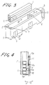
- the magazine unit 3 comprises a rectangular hollow elongate unit body 7 which is open at upper and lower ends and a pair of first and second magazine guides 5, 6 disposed in the unit body 7.
- the first and second magazine guides 5, 6 have respective vertical grooves 4 opening toward each other.
- the grooves 4 have a width slightly larger than the width of the magazines 1 for receiving the opposite ends of the magazines 1.
- the second magazine guide 6 is slidably adjustable in position in the direction of the arrow a (FIG. 3).
- a grip handle 8 is attached to one of opposite longitudinal ends of the unit body 7.
- two pairs of a receiver lever 9 and a presser lever 10 are swingably mounted by pivot pins 11 on one side wall of the unit body 7, these lever pairs being spaced longitudinally of the unit body 7 at an interval which is slightly smaller than the length of shortest magazines 1 that can be placed in the magazine unit 3.
- the receiver lever 9 in each pair has a hook 9a on its lower end.
- the receiver lever 9 in each pair is normally urged by a first spring 12a to turn in the direction of the arrow b for positioning the hook 9a underneath the lower open end of the unit body 7 to engage the lowermost magazine 1 in the magazine unit 3 thereby to prevent the magazine stack from dropping out of the unit body 7.
- the presser lever 10 in each pair has a presser 10a projecting into the unit body 7 for pressing engagement with one, at a time, of the magazines 1.
- the presser lever 10 is normally urged by a spring 12b to turn about the pivot pin 11 in the direction of the arrow c for thereby keeping the presser 10a out of pressing engagement with the magazines 1.
- the presser lever 10 is turned by an applied external force in the direction of the arrow b to hold the presser 10a against a side wall of the magazine 1 which is located on the lowermost magazine 1 that has just been released from the hook 9a.
- the unit body 7 has a pair of flanges 13 extending away from each other from the upper ends of the lateral side walls of the unit body 7.
- the stock unit 14 includes a plurality of unit guides 15 inclined about 35° to the horizontal direction for positioning the magazine units 3 in transversely constant intervals or pitches and supporting, from below, the flanges 13 of the magazine units 3, respectively, suspended in guide grooves defined between the unit guides 15, and a unit stopper 16 disposed at one longitudinal end of the unit guides 15 for positioning the magazine units 3 in their longitudinal direction, the unit guides 15 and the unit stopper 16 being suspended from a base 17.
- a pair of transmission-type photoelectric switches 18 is fixed to the base 17 in the vicinity of the grip handles 8 of the magazine units 3. The photoelectric switches 18 are spaced from each other by a distance larger than the width of the array of magazine units 3 supported by the stock unit 14.
- the magazines 1 in the magazine units 3 are transferred to a supply unit 19 (FIGS. 2 and 7).
- the supply unit 19 includes a frame 20 disposed independently below the arrayed magazine units 3 supported by the stock unit 14.
- the frame 20 is supported on and slidable along a pair of parallel shafts 21 which is fixed to the base 17 perpendicularly to the longitudinal direction of the magazines 1, the frame 20 being movable along the shafts 21 by means of a ball screw 22 extending parallel to and between the shafts 21 and connected to a motor (not shown).
- the supply unit 19 also includes holding means in the form of array of chutes 23 removably mounted on the frame 20 and inclined at the same angle as the unit guides 15 (FIG. 5).
- the chutes 23 have respective grooves 24 defined on their upper surfaces for receiving respective arrays of parts 2 discharged from the magazines 1.
- the chutes 23 are longitudinally aligned with the magazine units 3 supported by the stock unit 14, as shown in FIG. 2.
- a supporting means including a pair of gripper jaws 25 are angularly movably mounted by a pivot pin 26 fixed to each of the chutes 23.
- the gripper jaws 25 are normally urged by a spring 27 toward each other for gripping the front end of one of the magazines 1, the gripper jaws 25 having a pair of respective rollers 28.
- a cam lever 30 (FIG. 7) is vertically swingably mounted by a pivot pin 29 on each of the chutes 23 and includes a wedge-shaped cam 30a (FIG. 8) which is located near the rollers 28.
- the cam lever 30 is normally urged by a spring 30b away from the rollers 28.
- a holder slider 31 is slidably mounted on a pair of shafts 32 (only one shown in FIG. 7) fixed to each chute 23 and extending parallel thereto.
- the holder slider 31 is normally urged by a spring 33 to move in the direction of the arrow e for supporting thereon the bottom of the front end of the corresponding magazine 1.
- the holder slider 31 is displaced to release the magazine 1.
- a reflection-type photoelectric switch 34 is mounted on each chute 23 for detecting whether there is a part 2 discharged from the magazine 1.
- An array of guides 35 belonging to said supporting means is removably mounted on the frame 20 remotely from and in longitudinal alignment with the array of chutes 23, respectively.
- Each of the guides 35 has a groove 36 (FIG. 8) opening toward the corresponding chute 23 and having a width slightly larger than that of the magazine 1 for receiving the rear end thereof.
- Holder plates 37 are attached to the guides 35, respectively, and normally urged by springs 38 to hold the bottoms of the rear surfaces of the magazines 1. The holder plates 37 can be retracted out of engagement with the magazines 1 to release them by pulling knobs 39 connected to the holder plates 37, respectively, in the direction of the arrow e .
- a plurality of swingable buckets 40 are disposed in the frame 20 and angularly movably mounted by respective pivot pins 41 in the frame 20.
- Each of the swingable buckets 40 can accommodate a plurality of magazines 1 therein and has one longitudinal end open.
- Each swingable bucket 40 can be turned about the pivot pin 41 by means of a fluid cylinder 42 interconnected between the bucket 40 and the frame 20.
- the magazines 1 can be fed into the supply unit 19 by means of an escape unit 43 (FIGS. 7, 9 and 10).
- the escape unit 43 includes an escape base 44 disposed below the chutes 23 and the guides 35 and slidable along a pair of parallel shafts 45 extending transversely of the magazines 1 and fixed to the frame 20.
- the escape base 44 can be moved along the parallel shafts 45 on the frame 20 by means of an endless belt 46 attached to the escape base 44 and driven by a motor (not shown).
- a fluid cylinder 47 is mounted on the escape base 44 for exerting an external force to each cam lever 30 to cause the wedge-shaped cam 30a to open the gripper jaws 25 away from each other.
- Another fluid cylinder 48 is mounted on the escape base 44 for imposing an external force on each of the holder sliders 31 movably mounted on the respective chutes 23.
- an openable bucket 49 is fixedly mounted on the escape base 44 below each magazine unit 3 for receiving magazines 1 which have been released from the gripper jaws 25 and the holder slider 31.
- the bucket 49 has a bottom 49a swingable about a pivot pin 50 and coupled to a fluid cylinder 51 fixed to the escape base 44.
- the bottom 49a can therefore be swung open by the fluid cylinder 51 to allow any magazines 51 in the bucket 49 to drop into the swingable bucket 40.
- a plate 52 is disposed above the escape base 44 and coupled to a piston rod 53a of a fluid cylinder 53 attached to the escape base 44.
- the plate 52 is movable by the fluid cylinder 53 in a direction transversely of the magazine unit 3 and hence a stack of magazines 1 stored therein.
- a pair of control levers 54a, 54b is angularly movably mounted on the plate 52 by means of a pivot pin 55.
- the control levers 54a, 54b have respective rollers 54c mounted on their lower ends and engageable by a wedge-shaped cam 56a connected to a fluid cylinder 56 supported on the plate 52.
- the control levers 54a, 54b are swung toward each other by the wedge-shaped cam 56a driven by the fluid cylinder 56 to engage and move the receiver and presser levers 9, 10 in the directions of the arrows c , b , respectively.
- a swing lever 57 is attached to the upper end of a rotatable rod 59a of a rotary fluid cylinder 59 which is vertically movable by a fluid cylinder 58 supported by the plate 52.
- the swing lever 57 is positioned slightly below the bottom of the lowermost magazine 1 in the magazine unit 3.
- the swing lever 57 is lowered by the fluid cylinder 58 while the plate 52 is in the uppermost position, the swing lever 57 is positioned below the holder slider 31 and the holder plate 37. As the swing lever 57 is turned to the position of FIG. 10, it underlies the magazine 1.
- a pair of transmission-type photoelectric switches 60 is mounted on the bucket 49 and spaced from each other across the downfall passage of magazines 1 in the bucket 49.
- a reflection-type photosensitive switch 61 is supported on a vertical bar 66 secured to the plate 52. The photosensitive switch 61 serves to detect the lowermost magazine 1 in the magazine unit 3 when the plate 52 is raised to the uppermost position by the fluid cylinder 53.
- Two reflection-type photoelectric switches 62 (only one shown) are also supported on the vertical bar 66 below the photoelectric switch 61. When the plate 52 reaches the uppermost position, these photoelectric switches 62 have their optical axes positioned slightly below the bottom of the lowermost magazine 1 in the magazine unit 3. The photoelectric switches 62 are spaced from each other by a distance slightly smaller than the length of any shortest magazine which may be stored in the magazine unit 3.
- the parts 2 on any chute 23 are successively inserted by an insertion head 63 into a printed-circuit board 64.
- the insertion head 63 is movable by a suitable actuator between a first position over the front end of the selected chute 23 and a second position over the printed-circuit board 64.
- the insertion head 63 has a pair of grip fingers 65 (only one shown) drivable by a suitable actuator for gripping one, at a time, of the parts 2 on the front end of the chute 23.
- the grip fingers 65 grip one part 2
- the part 2 is released from the grip fingers 65 for insertion into the printed-circuit board 64.
- the first and second magazine guides 5, 6 in a magazine unit 3 are spaced from each other by a distance slightly larger than the length of the magazines 1 to be placed in the magazine unit 3, and are fixed in place to the magazine unit 3. Then, a stack of magazines 1 is placed in the magazine unit 3 between the first and second magazine guides 5, 6 with the opposite ends of the magazines 1 being received in the grooves 4 of the first and second magazine guides 5, 6, as shown in FIGS. 3 and 4.
- a plurality of magazine units 3 with stacks of magazines 1 accommodated therein are inserted onto and along the unit guides 15 (FIGS. 5 and 6) of the stock unit 14, and pushed on until they are stopped by the unit stopper 16.
- the supply unit 19 is moved to a position confronting the magazines 1 of the stock unit 14 in order to transfer the magazines 1 from the stock unit 14 to the chutes 23 and the guides 35 of the supply unit 19, as illustrated in FIG. 2.
- the escape unit 43 is thereafter operated for successively releasing the lowermost magazines 1 from the magazine units 3 so they will be held by the chutes 23 and the guides 35 of the supply unit 19.
- the various fluid cylinders used in the parts feeder will be described as air cylinders, though they may be hydraulic cylinders.
- the air cylinder 47 (FIG. 7) on the escape base 44 is actuated to project its piston rod under air pressure supplied thereto for thereby camming the gripper jaws 25 on the chute 23 to be opened and disenaged from the front end of the magazine 1.
- the air cylinder 48 on the escape base 44 is also actuated under air pressure to project its piston rod for moving the holder slider 31 in the direction of the arrow f , thus releasing the front end of the magazine 1.
- the released magazine 1 drops at the front end and then at the rear end, and is stored in the bucket 49 attached to the escape base 44 (FIG. 9).
- the photoelectric switches 60 produce a signal indicating that the magazine 1 has been stored in the bucket 49.
- the air cylinder 48 is released to move the holder slider 31 in the direction of the arrow e .
- the plate 52 is lifted by the air cylinder 53, and the swing lever 57 on the plate 52 is raised to its uppermost position by the air cylinder 58 and turned by the rotary air cylinder 59 until the swing lever 57 is positioned slightly below the bottom of the lowermost magazine 1 in the magazine unit 3 in underlapping relation to the magazine 1.
- the reflection-type photoelectric switch 61 on the plate 52 ascertains whether the magazine unit 3 contains a magazine 1 to be transferred. If no magazine 1 is contained, then the photoelectric switch 61 produces an alarm signal.
- the air cylinder 56 is actuated to move the cam 56a upwardly to turn the control levers 54a, 54b about the pivot pin 55 for engaging and angularly moving the front and rear receiver levers 9 on the magazine unit 3 in the direction of the arrow c (FIG. 9) and also the front and rear presser levers 10 on the magazine unit 3 in the direction of the arrow b . Therefore, the magazine 1 on the lowermost magazine 1 in the magazine unit 3 is held by the presser 10a (FIG. 4), whereas the lowermost magazine 1 is released from the hook 9a to fall onto the swing lever 57 below the magazine unit 3, as illustrated in FIG. 10.
- the swing lever 57 is gradually lowered by the air cylinder 58 to the lowermost position as indicated by the dot-and-dash-line position in FIG. 10.
- the magazine 1 on the swing lever 57 is now positioned as shown in FIG. 7, whereupon the bottom of the front end of the magazine 1 is supported on the holder slider 31 and the rear end of the magazine 1 is received in and transversely positioned by the groove 36 in the guide 35 (FIG. 8), the bottom of the rear end of the magazine 1 being retained on the holder plate 37.
- the magazine 1 is now released from the swing lever 57 and vertially spaced therefrom.
- the air cylinder 56 is operated again to lower the cam 56a for retracting the control levers 54a, 54b out of engagement with the receiver and presser levers 9, 10.
- the receiver lever 9 is allowed to turn in the direction of the arrow b (FIG. 9) below the magazine unit 3, and the presser lever 10 is also allowed to turn in the direction of the arrow c out of pressing engagement with the magazine 1, which then drops as the lowermost magazine 1 onto the receiver lever 9.
- the photoelectric switch 61 If no lowermost magazine 1 is detected, the photoelectric switch 61 produces an alarm signal for magazine replenishment.
- the front and rear photoelectric switches 62 ascertain whether the magazine 1 to be transferred has dropped completely off the magazine unit 3. If any of the photoelectric switches 62 detects the presence of the magazine 1, it produces a signal indicating a transfer failure to stop the entire operation of the parts feeder.
- the swing lever 57 is returned by the rotary air cylinder 59 out of underlapping relation to the lowermost magazine 1. Then, the plate 52 is lowered by the air cylinder 53, and the air cylinder 47 is released to allow the gripper jaws 25 to be closed for forcibly gripping the front end of the magazine 1 transversely.
- the magazine 1 is thus transferred to the supply unit 19, the parts 1 are gravity-fed from the magazine 1 into the groove 24 of the chute 23.
- the above transfer cycle is repeated each time the escape unit 43 is moved along the shafts 45 to a position below one of the successive magazine units 3. Therefore, the successive chutes 23 are filled up with the respective parts 2 supplied from the magazines 1 held in the supply unit 19.
- the parts 2 on any of the chutes 23 can successively be applied to the printed-circuit board 64 (FIG. 1) by the insertion head 63 to which the chute 23 has been moved.
- the sensor 34 FIG. 7
- the sensor 34 upon successive consumption of the parts by the insertion head 63, the sensor 34 generates a signal indicating that the magazine 1 has run short of parts.
- the escape unit 43 then moves to the empty magazine 1, and drops the empty magazine 1 into the bucket 49 and transfer the next magazine 1 full of parts 1 to the supply unit 19 from the magazine unit 3.
- the magazine unit 3 is manually pulled out of the stock unit 14 by gripping the grip handle 8 and a new stack of loaded magazines 1 is placed in the magazine unit 3, which is then inserted into the stock unit 14.
- the aforesaid process may be repeated to replenish the parts feeder with desired parts without shutdown of the parts feeder.
- a magazine unit 3 is pulled out of the stock unit 14, and the first magazine guide 6 is positionally adjusted with respect to the first magazine guide 5 to meet the length of new magazines 1 to be loaded.
- the knob 39 is manually pulled to move the holder plate 37 in the direction of the arrow e out of engagement with a magazine 1 to be replaced.
- the rear end of the magazine 1 is pushed downwardly while preventing, by hand, the parts 2 from falling off the front end of the magazine 1, and the magazine 1 is pulled out backwards. Thereafter, the chute 23 and the guide 35 are replaced with those which meet the size of the new magazines.
- the magazine unit when the magazines are removed from a magazine unit, the magazine unit can be loaded with new magazines full of parts without shutdown of the parts feeder since the stock unit is structurally independent of the supply unit.
Landscapes
- Engineering & Computer Science (AREA)
- Manufacturing & Machinery (AREA)
- Microelectronics & Electronic Packaging (AREA)
- Automatic Assembly (AREA)
- De-Stacking Of Articles (AREA)
- Warehouses Or Storage Devices (AREA)
- Feeding Of Articles To Conveyors (AREA)
- Supply And Installment Of Electrical Components (AREA)
Claims (19)
- Einrichtung zum Zuführen von Bauteilen mit
einer Lagereinheit (14), die eine Vielzahl von Seite an Seite angeordneter Magazineinheiten (3) aufweist, die jeweils einen Stapel an Magazinen (1) aufnehmen, welche jeweils eine Reihe an Bauteilen (2) bevorraten und einer Zufuhreinheit (19), die in einer Horizontalebene zum selektiven Zuführen der Bauteile (2) an einen Bestückungskopf (63) bewegbar ist,
dadurch gekennzeichnet, daß die Zufuhreinheit (19) eine Vielzahl von Seite an Seite angeordneter Einrichtungen aufweist, die jeweils eine Aufnahmeeinrichtung (25, 31, 35, 36) zur Aufnahme eines aus den Maganzineinheiten (3) entfernten Magazins (1) und eine Halteeinrichtung (23) zum Halten der aus dem Magazin (1) abgegebenen Reihe an Bauteilen (2) aufweisen, wobei die Zufuhreinheit (19) in einer ersten Richtung quer zu einer zweiten Richtung bewegbar ist, in welcher die Einrichtungen Seite an Seite angeordnet sind; und
daß die Einrichtung zum Zuführen von Bauteilen eine Ausbringeinheit (43) aufweist zum Entfernen jeweils eines Magazins aus den Magazineinheiten (3) und Übergeben des Magazins (1) an die Aufnahmeeinrichtung (25, 31, 35, 36) der Zufuhreinheit (19). - Einrichtung zum Zuführen von Bauteilen nach Anspruch 1, dadurch gekennzeichnet, daß die Aufnahmeeinrichtung (25, 31, 35, 36) ein Haltergleitstück (31) zum Halten eines vorderen Endes des Magazins (1) und eine Führung (35) zum Halten eines hinteren Endes des Magazins (1) aufweist, wobei das Haltergleitstück (31) tiefer als die Führung (35) angeordnet ist und das Haltergleitstück (31) sowie die Führung (35) selektiv betätigbar sind zum Lösen des Magazins (1) zum Fallen aufgrund der Schwerkraft.
- Einrichtung zum Zuführen von Bauteilen nach Anspruch 2, dadurch gekennzeichnet, daß die Aufnahmeeinrichtung weiterhin ein Paar an Greiferbacken (25) zum Quergreifen des vorderen Endes des Magazins (1) aufweist.
- Einrichtung zum Zuführen von Bauteilen nach Anspruch 2, dadurch gekennzeichnet, daß die Führung (35) eine Nut (36) zum Aufnehmen des hinteren Endes des Magazins (1) aufweist.
- Einrichtung zum Zuführen von Bauteilen nach Anspruch 1, dadurch gekennzeichnet, daß die Lagereinheit (14) um etwa 35 Grad zu einer Horizontalrichtung geneigt ist.
- Einrichtung zum Zuführen von Bauteilen nach Anspruch 1, gekennzeichnet durch eine Basis (17) an welcher die Zufuhreinheit (19) bewegbar angeordnet ist, wobei die Lagereinheit (14) an der Basis (17) festgelegt angeordnet ist.
- Einrichtung zum Zuführen von Bauteilen nach Anspruch 6, dadurch gekennzeichnet, daß die Lagereinheit (14) von der Basis (17) herabhängend angeordnet ist.
- Einrichtung zum Zuführen von Bauteilen nach Anspruch 7, dadurch gekennzeichnet, daß jede der Magazineinheiten (3) Flansche (13) aufweist, daß die Lagereinheit (14) eine Einrichtung (15) zum Beladen und Entladen der Magazineinheiten (3) in die und aus der Lagereinheit (14) heraus durch deren eines Ende besitzt, daß die Belade- und Entladeeinrichtung Einheitenführungen (15) zur Aufnahme der Flansche (13) der Magazineinheiten (3) und zwischen den Einheitenführungen (15) gebildete Führungsnuten aufweist zur jeweiligen Anordnung der Magazineinheiten (3) darin, die von den Einheitenführungen (15) gehalten sind.
- Einrichtung zum Zuführen von Bauteilen nach Anspruch 7, dadurch gekennzeichnet, daß die Lagereinheit (14) Führungsnuten zum Einführen der Magazineinheiten (3) darin jeweils längs zu den Magazinen (1) aufweist.
- Einrichtung zum Zuführen von Bauteilen nach Anspruch 7, gekennzeichnet durch einen Sensor (18) zum Erfassen, ob die Magazinbohrungen richtig in der Lagereinheit (14) eingesetzt sind.
- Einrichtung zum Zuführen von Bauteilen nach Anspruch 7, dadurch gekennzeichnet, daß jede Magazineinheit (3) einen Aufnahmehebel (9) zum wahlweise Halten und Lösen der Unterseite des untersten Magazins (1) in der Magazineinheit (3) besitzt.
- Einrichtung zum Zuführen von Bauteilen nach Anspruch 11, dadurch gekennzeichnet, daß jede Magazineinheit (3) einen Druckhebel (10) zum transversalen Halten und Lösen des untersten Magazins (1) in der Magazineinheit (3) aufweist.
- Einrichtung zum Zuführen von Bauteilen nach Anspruch 12, dadurch gekennzeichnet, daß die Aufnahme- und Druckhebel (9, 10) zu zwei Paaren vorgesehen sind, die in einem Abstand angeordnet sind, der kleiner ist als die Länge der in der Magazineinheit (3) angeordneten Magazine (1).
- Einrichtung zum Zuführen von Bauteilen nach Anspruch 12, dadurch gekennzeichnet, daß jede Magazineinheit (3) eine Magazinführung (5, 6) mit einer Nut (4) aufweist, die eine Breite größer als die Breite der in der Magazineinheit (3) und in einer Längsrichtung der Magazineinheit (3) bewegbar angeordneten Magazine (1) aufweist.
- Einrichtung zum Zuführen von Bauteilen nach Anspruch 11, dadurch gekennzeichnet, daß jede Magazineinheit (3) einen an einer Außenfläche davon angeordneten Handgriff (8) aufweist.
- Einrichtung zum Zuführen von Bauteilen nach Anspruch 1, dadurch gekennzeichnet, daß die Ausbringeinheit (43) in der ersten Richtung und zu den in der Lagereinheit (14) angeordneten Magazineinheiten (3) hin und davon weg bewegbar ist und weiterhin eine Basis (17) aufweist, an welcher die Lagereinheit (19) bewegbar angeordnet ist und daß die Lagereinheit (14) an der Basis (17) festgelegt angeordnet ist.
- Einrichtung zum Zuführen von Bauteilen nach Anspruch 16, dadurch gekennzeichnet, daß die Ausbringeinheit (43) unterhalb der Lagereinheit (14) angeordnet ist und unabhängig von der Lagereinheit (14) und der Zufuhreinheit (19) bewegbar ist.
- Einrichtung zum Zuführen von Bauteilen nach Anspruch 16, dadurch gekennzeichnet, daß die Ausbringeinheit (43) ein Gefäß (40) zur Lagerung leerer Magazine (1) aufweist, die frei sind von Bauteilen (2).
- Einrichtung zum Zuführen von Bauteilen (2) zum Zuführen jeweils eines der Bauteile (2) an eine vorbestimmte Position, mit einer Lagereinheit (14), die eine Vielzahl von Seite an Seite angeordneter Magazineinheiten (3) aufweist, die jeweils einen Stapel an Magazinen (1) aufnehmen, welche eine Reihe an Bauteilen (2) bevorraten und einer Zufuhreinheit (19) dadurch gekennzeichnet, daß die Zufuhreinheit (19) eine Vielzahl von Seite an Seite angeordneter Magazine (1) hält, wobei eines der Magazine aus jeder der Magazineinheiten (3) entfernbar ist, daß die Zufuhreinheit jeweils eines der Bauteile (2) aus jeweils einem der gehaltenen Magazine (1) an eine vorbestimmte Position zuführt, wobei die Zufuhreinheit (19) unabhängig von der Lagereinheit (14) bewegbar ist.
Applications Claiming Priority (2)
| Application Number | Priority Date | Filing Date | Title |
|---|---|---|---|
| JP169073/85 | 1985-07-31 | ||
| JP60169073A JPH06102487B2 (ja) | 1985-07-31 | 1985-07-31 | 部品供給装置 |
Publications (3)
| Publication Number | Publication Date |
|---|---|
| EP0210662A2 EP0210662A2 (de) | 1987-02-04 |
| EP0210662A3 EP0210662A3 (en) | 1989-08-09 |
| EP0210662B1 true EP0210662B1 (de) | 1993-05-26 |
Family
ID=15879823
Family Applications (1)
| Application Number | Title | Priority Date | Filing Date |
|---|---|---|---|
| EP19860110630 Expired - Lifetime EP0210662B1 (de) | 1985-07-31 | 1986-07-31 | Einrichtung zum Zuführen von Bauteilen |
Country Status (5)
| Country | Link |
|---|---|
| US (1) | US4763811A (de) |
| EP (1) | EP0210662B1 (de) |
| JP (1) | JPH06102487B2 (de) |
| CA (1) | CA1304051C (de) |
| DE (1) | DE3688484T2 (de) |
Families Citing this family (16)
| Publication number | Priority date | Publication date | Assignee | Title |
|---|---|---|---|---|
| JPH0620910B2 (ja) * | 1987-04-20 | 1994-03-23 | 株式会社村田製作所 | 電子部品チツプ収納カセツト |
| IT1229335B (it) * | 1989-05-04 | 1991-08-08 | Electronic System | Magazzino automatico intelligente di circuiti integrati e componenti discreti, in particolare per l'impiego in macchine per l'inserimento automatico di circuiti integrati e/o componenti su schede, pannelli e/o simili. |
| US5217120A (en) * | 1989-08-31 | 1993-06-08 | Goldstar Co., Ltd. | Apparatus for loading and unloading sleeves for integrated circuit ester |
| GB2237563B (en) * | 1989-10-30 | 1994-06-01 | Mitel Telecom Ltd | Method and apparatus for use in handling magazines |
| JPH03291000A (ja) * | 1990-04-07 | 1991-12-20 | Murata Mfg Co Ltd | 電子部品チップ整列装置 |
| US5116185A (en) * | 1990-05-01 | 1992-05-26 | Lsi Logic Corp. | Vibratory tube-to-tube transfer system |
| JP3006064B2 (ja) * | 1990-10-01 | 2000-02-07 | 株式会社アドバンテスト | Ic試験装置 |
| US5117963A (en) * | 1990-12-12 | 1992-06-02 | Micron Technology, Inc. | System for automated handling of symmetrical supply tubes |
| TW287235B (de) * | 1994-06-30 | 1996-10-01 | Zenshin Test Co | |
| US5752797A (en) * | 1996-04-08 | 1998-05-19 | International Business Machines Corporation | Automated chamfering apparatus and method |
| US5931630A (en) * | 1998-01-26 | 1999-08-03 | Harmony Technology Corp. | Material feeding apparatus for use in a surface mounting system |
| JP2001140731A (ja) | 1999-11-15 | 2001-05-22 | Bosch Automotive Systems Corp | 電磁式燃料噴射弁 |
| TW507492B (en) * | 2000-11-24 | 2002-10-21 | Mirae Corpration | Feeder for surface mounting device |
| WO2018100627A1 (ja) * | 2016-11-29 | 2018-06-07 | 株式会社Fuji | 部品供給システム、および部品装着機 |
| SG10201706437VA (en) * | 2017-08-07 | 2019-03-28 | Rokko Systems Pte Ltd | Method and apparatus for pcb sawing |
| DE102022110258A1 (de) * | 2022-04-27 | 2023-11-02 | Krones Aktiengesellschaft | Magazineinheit, Verpackungsvorrichtung und Verfahren zum Zusammenfassen von Artikelzusammenstellungen |
Citations (1)
| Publication number | Priority date | Publication date | Assignee | Title |
|---|---|---|---|---|
| EP0080512A1 (de) * | 1981-06-01 | 1983-06-08 | Matsushita Electric Industrial Co., Ltd. | Vorrichtung zum einbau eines elektrischen teiles |
Family Cites Families (7)
| Publication number | Priority date | Publication date | Assignee | Title |
|---|---|---|---|---|
| US4037756A (en) * | 1976-06-21 | 1977-07-26 | Trans World Display Corporation | Display-dispenser rack |
| JPS5534461A (en) * | 1978-08-31 | 1980-03-11 | Matsushita Electric Industrial Co Ltd | Device for automatically inserting electric part |
| JPS567827A (en) * | 1979-06-25 | 1981-01-27 | Taiyo Yuden Co Ltd | Supply and line-up device for electronic parts |
| JPS579720A (en) * | 1980-06-19 | 1982-01-19 | Takaseen:Kk | Preparation of chinese herbal remedial tea |
| US4401234A (en) * | 1981-06-01 | 1983-08-30 | Universal Research Laboratories, Incorporated | Apparatus for applying integrated circuits to a circuit board |
| DE3217531C2 (de) * | 1982-05-10 | 1985-01-03 | Ekkehard Ing.(Grad.) 8011 Zorneding Ueberreiter | Vorrichtung zum Prüfen und Sortieren von länglichen elektronischen Bauteilen, insbesondere von integrierten Chips |
| US4599026A (en) * | 1985-02-26 | 1986-07-08 | Amp Incorporated | Apparatus for providing a continuous supply of workpieces |
-
1985
- 1985-07-31 JP JP60169073A patent/JPH06102487B2/ja not_active Expired - Fee Related
-
1986
- 1986-07-31 DE DE8686110630T patent/DE3688484T2/de not_active Expired - Fee Related
- 1986-07-31 CA CA000515091A patent/CA1304051C/en not_active Expired - Lifetime
- 1986-07-31 EP EP19860110630 patent/EP0210662B1/de not_active Expired - Lifetime
- 1986-07-31 US US06/891,028 patent/US4763811A/en not_active Expired - Lifetime
Patent Citations (1)
| Publication number | Priority date | Publication date | Assignee | Title |
|---|---|---|---|---|
| EP0080512A1 (de) * | 1981-06-01 | 1983-06-08 | Matsushita Electric Industrial Co., Ltd. | Vorrichtung zum einbau eines elektrischen teiles |
Also Published As
| Publication number | Publication date |
|---|---|
| EP0210662A2 (de) | 1987-02-04 |
| DE3688484D1 (de) | 1993-07-01 |
| US4763811A (en) | 1988-08-16 |
| JPS6231613A (ja) | 1987-02-10 |
| CA1304051C (en) | 1992-06-23 |
| DE3688484T2 (de) | 1993-09-23 |
| JPH06102487B2 (ja) | 1994-12-14 |
| EP0210662A3 (en) | 1989-08-09 |
Similar Documents
| Publication | Publication Date | Title |
|---|---|---|
| US4763811A (en) | Parts feeder | |
| GB2150920A (en) | Equipment and method for feeding packaging blanks to a packaging machine | |
| US4761106A (en) | Part feeder | |
| US4621967A (en) | Automatic board loaders | |
| CN1138817A (zh) | 芯片自动补充机 | |
| CA1215220A (en) | Automatic board loaders | |
| JPS628370B2 (de) | ||
| JPS6241440B2 (de) | ||
| JPH03238233A (ja) | Icテスターのためにスリーブを積み降ろしするための装置 | |
| US4829748A (en) | Apparatus for arraying parts on respective trays | |
| CA1285240C (en) | Apparatus for automatically supplying electrical components | |
| EP0415293B1 (de) | Vorrichtung zur Speicherung von Reissverschlussschiebern | |
| JPH0336736B2 (de) | ||
| US5273078A (en) | Rod-type three-dimensional loom and continuous operating method | |
| CA2168160A1 (en) | Case-feeding unit in an automatic apparatus for packaging manufactured articles into cases, and automatic case-feeding method relating to same | |
| US5217120A (en) | Apparatus for loading and unloading sleeves for integrated circuit ester | |
| JP2023014589A (ja) | 試験管整列装置 | |
| JPS62146821A (ja) | マガジン供給方法 | |
| CN117645071B (zh) | 一种包埋盒收纳装置 | |
| JPS6138221Y2 (de) | ||
| JPS61127402A (ja) | Ic詰め替え装置 | |
| GB2061892A (en) | Cassette correlator | |
| JP2955002B2 (ja) | 樹脂成形機のタブレット供給装置 | |
| JPS59124800A (ja) | ステイツクマガジン供給装置 | |
| JPS6176224A (ja) | 電子部品の自動供給装置 |
Legal Events
| Date | Code | Title | Description |
|---|---|---|---|
| PUAI | Public reference made under article 153(3) epc to a published international application that has entered the european phase |
Free format text: ORIGINAL CODE: 0009012 |
|
| AK | Designated contracting states |
Kind code of ref document: A2 Designated state(s): DE FR GB |
|
| PUAL | Search report despatched |
Free format text: ORIGINAL CODE: 0009013 |
|
| AK | Designated contracting states |
Kind code of ref document: A3 Designated state(s): DE FR GB |
|
| 17P | Request for examination filed |
Effective date: 19891124 |
|
| 17Q | First examination report despatched |
Effective date: 19910418 |
|
| GRAA | (expected) grant |
Free format text: ORIGINAL CODE: 0009210 |
|
| AK | Designated contracting states |
Kind code of ref document: B1 Designated state(s): DE FR GB |
|
| REF | Corresponds to: |
Ref document number: 3688484 Country of ref document: DE Date of ref document: 19930701 |
|
| ET | Fr: translation filed | ||
| RIN2 | Information on inventor provided after grant (corrected) |
Free format text: MAE, TAKAHARU * KINOSHITA, HIROMI * MAEDA, YOSHINOBU * FUJIWARA, KOJI * NAKAGAWA, HIROSHI |
|
| PLBE | No opposition filed within time limit |
Free format text: ORIGINAL CODE: 0009261 |
|
| STAA | Information on the status of an ep patent application or granted ep patent |
Free format text: STATUS: NO OPPOSITION FILED WITHIN TIME LIMIT |
|
| 26N | No opposition filed | ||
| REG | Reference to a national code |
Ref country code: GB Ref legal event code: 746 Effective date: 19970901 |
|
| PGFP | Annual fee paid to national office [announced via postgrant information from national office to epo] |
Ref country code: FR Payment date: 20000711 Year of fee payment: 15 |
|
| PGFP | Annual fee paid to national office [announced via postgrant information from national office to epo] |
Ref country code: GB Payment date: 20000726 Year of fee payment: 15 |
|
| PGFP | Annual fee paid to national office [announced via postgrant information from national office to epo] |
Ref country code: DE Payment date: 20000729 Year of fee payment: 15 |
|
| PG25 | Lapsed in a contracting state [announced via postgrant information from national office to epo] |
Ref country code: GB Free format text: LAPSE BECAUSE OF NON-PAYMENT OF DUE FEES Effective date: 20010731 |
|
| GBPC | Gb: european patent ceased through non-payment of renewal fee |
Effective date: 20010731 |
|
| PG25 | Lapsed in a contracting state [announced via postgrant information from national office to epo] |
Ref country code: FR Free format text: LAPSE BECAUSE OF NON-PAYMENT OF DUE FEES Effective date: 20020329 |
|
| PG25 | Lapsed in a contracting state [announced via postgrant information from national office to epo] |
Ref country code: DE Free format text: LAPSE BECAUSE OF NON-PAYMENT OF DUE FEES Effective date: 20020501 |
|
| REG | Reference to a national code |
Ref country code: FR Ref legal event code: ST |