EP0210961A1 - Anlage für die elektrolytische Herstellung von reaktiven Metallen in Salzschmelzen - Google Patents
Anlage für die elektrolytische Herstellung von reaktiven Metallen in Salzschmelzen Download PDFInfo
- Publication number
- EP0210961A1 EP0210961A1 EP86830207A EP86830207A EP0210961A1 EP 0210961 A1 EP0210961 A1 EP 0210961A1 EP 86830207 A EP86830207 A EP 86830207A EP 86830207 A EP86830207 A EP 86830207A EP 0210961 A1 EP0210961 A1 EP 0210961A1
- Authority
- EP
- European Patent Office
- Prior art keywords
- container
- plant according
- electrodes
- chamber
- molten salt
- Prior art date
- Legal status (The legal status is an assumption and is not a legal conclusion. Google has not performed a legal analysis and makes no representation as to the accuracy of the status listed.)
- Granted
Links
Images


Classifications
-
- C—CHEMISTRY; METALLURGY
- C25—ELECTROLYTIC OR ELECTROPHORETIC PROCESSES; APPARATUS THEREFOR
- C25C—PROCESSES FOR THE ELECTROLYTIC PRODUCTION, RECOVERY OR REFINING OF METALS; APPARATUS THEREFOR
- C25C7/00—Constructional parts, or assemblies thereof, of cells; Servicing or operating of cells
- C25C7/005—Constructional parts, or assemblies thereof, of cells; Servicing or operating of cells of cells for the electrolysis of melts
Definitions
- the present invention relates to a plant for the electrolytic production of metals in molten salt baths, particularly for reactive metals such as titanium, zirconium and hafnium.
- a first difficulty lies in the need to carry out the electrolysis in a substantially sealed container for the bath of molten salts, both because of the evolution of gas during the electrolysis and in order to avoid contamination of the bath by atmospheric gases.
- a second difficulty arises from the fact that the reactive metals mentioned above deposit on the cathode in the solid state as a result of the electrolysis, in the form of crystals adhering to the surface of the electrode, thus making it necessary to remove the cathode from the electrolytic cell to collect the metal.
- a further difficulty lies in the high reactivity of the metal produced when in contact with air at high temperatures whereby the metal produced must be cooled in an inert atmosphere to allow it to be stored subsequently.
- the object of the present invention is to provide a plant which enables the metal to be produced continuously, overcoming the difficulties mentioned above.
- a second object of the present invention is to provide a plant which is very versatile in use and such as to allow the processes of both extraction and refining of the reactive metal to be carried out in the electrolytic cell.
- a further object of the present invention is to provide a plant which, by virtue of its versatility, may be used for experimental purposes, by allowing the arrangement and configuration of the electrodes to be varied easily within the electrolytic cell.
- the present invention provides a plant characterised in that it comprises: - an outer casing, - means for maintaining an atmosphere substantially inert to the metal to be produced in the casing, - a container disposed within the casing and arranged to contain the molten salt bath and having an upper opening provided with a movable, cover, - a plurality of electrodes arranged to be suspended in the molten salt bath, - a plurality of electrical connecting and support means comprising, for each of the electrodes, a pair of electrically conductive elements disposed facing each other on two opposite walls of the container adjacent its opening, each of the electrodes being suspended in the molten salt bath resting on the said pair of conductive elements, and - handling means associated with the outer casing and adapted to remove any one of the said electrodes from the container.
- the plant according to the invention enables the electrolysis of molten salts to be carried out with an easy operation procedure equivalent to that which characterises electrolysis processes in aqueous solutions.
- the plant of the invention differs from prior art plants in that the container fulfils solely the function of containing the electrolyte and not that of achieving a gas seal for isolating the electrolysis environment from the external atmosphere, this latter being a function of the outer casing.
- This fact results in important operational advantages such as the possibility of keeping the molten salt bath at higher temperatures or the possibility of keeping a lower absolute pressure in the container than can be achieved in conventional plants.
- the plant allows the parts of the container in contact with the electrolyte to be made from materials such as mild steel with modest structural strength, particularly those compatible with electrolytes typically used, even under extremely high temperature and vacuum conditions.
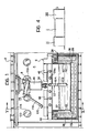
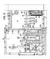
- a plant according to the invention comprises an outer metal casing 2 defining a main chamber 4 which is substantially isolated from the exterior and in which there are a container 6 for the bath of molten salts and for carrying out the electrolysis, and handling means 8.
- the casing 2 includes a prechamber 10 for allowing the exchange of material between the external environment and the main chamber 4.
- the prechamber 10 has gas tight doors 12 and 14 which put the prechamber 10 into communication with the chamber 4 and with the external environment respectively.
- vacuum pumps 16a and 16b with respective suction tubes 18a and 18b communicating respectively with the chamber 4 and with the prechamber 10 to maintain a controlled atmosphere, in particular an atmosphere inert to the metal to be produced, therein.
- 20a and 20b indicate reservoirs of pressurised inert gas, typically argon, which supply the inert gas to the casing 2 through tubes 22a and 22b respectively.
- the container 6 for the bath of molten salts is preferably of parallelapipedal shape and includes a heat insulating refractory lining 26 adjacent the casing 2 and a refractory inner lining 28.
- a metal shell 30 also of parallelapipedal shape, constituting the crucible for containing the bath of molten salts.
- the metal shell 30 is located resting on the base of the refractory inner lining 28.
- a plurality of heating elements 34 ( Figure 5) is incorporated in that part of the side walls of the refractory inner lining 28 facing the lateral walls of the shell 30 for providing, by radiation, the heat needed to bring the bath of salts within the crucible to melting point and possibly to maintain this temperature.
- a plurality of heating elements 34 is also incorporated in the base of the refractory inner lining 28.
- the bath of molten salts may be heated by electrodes immersed in the electrolyte and supplied by a variable voltage transformer instead of by use of the heating elements 34 or in cooperation with these heating elements.
- the container 6 has associated sealing means generally indicated 36 for preventing corrosive gases from inside the crucible penetrating the gap 32 and avoiding corrosion of the heating elements 34 protected.
- the sealing means comprise a vessel 38 encased along the entire upper edge of the refractory inner lining 28 and containing molten metal indicated 40.
- a fin 42 is immersed vertically in the molten metal in the vessel 38 and is welded to a flange 44 fixed to the upper edge of the shell 30.
- the choice of metal in the vessel depends on the temperature reached by the refractory material during the electrolysis, this metal having a melting point less than the operating temperature of the refractory material.
- a tube 24 passes through the wall of the container 6 and communicates with the gap 32 and with the vacuum pump 16a in parallel with the tube 18a so as to maintain a pressure in the gap 32 which is substantially equal to the pressure existing in the chamber 4.
- the outer casing 2 supports a frame structure 46 overlying the upper edge of the refractory inner lining 28 and acting as a support for a plurality of raisable cover members 48 which, when they rest on the frame structure 46 cover the container 6, avoiding any substantial outflow of gaseous products from the electrolysis in the container 6 into the chamber 4.
- Each cover member 48 has an associated fluid actuator 50 articulated to the wall of the outer casing 2 and arranged to allow the respective cover member to be raised into a vertical position to allow access to the handling means 8 within the container 6.
- Electrodes 52 resting on means 54a and 54b for supporting them and connecting them electrically (Figure 9).
- Each of the support and electrical connection means 54a and 54b comprises an electrically conductive member 56 constituted by a hollow steel bar surrounded tightly by an electrically insulating refractory sleeve 58 which is inserted in a tubular metal member 62.
- Each tubular member 62 extends through the frame structure 46 filled with refractory material in a direction perpendicular to the respective wall of the container 6.
- Each bar 56 has its end 64 outside the container 6 connected to electrical supply means 66 which supply a direct current I and its other end 68 projecting inwardly of the container 6.
- the end 68 of each bar has a dihedron shaped seat 70.
- each bar 56 Within the cavity of each bar 56 are heat exchange means constituted by two concentric tubes 72 and 74 in which a cooling fluid is circulated, being fed in at 76 and leaving at 78.
- the circulation of cooling fluid during production of the metal allows the bar itself to be kept at a high level of electrical conductivity, improving the power efficiency of the plant.
- Figure 10 illustrates in detail the device for mounting each bar 56 on the casing 2 for preventing air from entering the container 6 or the gaseous products from leaving it during the operation of the plant and for achieving electrical insulation of each bar.
- each bar 56 is welded an annular plate 82 gripped by stud bolts 84 between two annular plates 86 and 88.
- the annular plate 88 is welded to the outer casing 2 and compresses an annular sealing washer between it and the plate 82.
- a bush 92 of electrically insulating material such as asbestos or Teflon.
- An annular sealing washer 94 is interposed between the plate 82 and the plate 86.
- the plate 86 surrounds an annular washer 96 which surrounds a metal bush 98 welded to the bar 56.
- Channels 100 and 102 respectively are provided in the plate 88 and in the bush 98 for the circulation of cooling fluid.
- FIG 11 illustrates an electrode 52, particularly a cathode, suitable for use in the plant of the invention.
- the electrode comprises a body 104 which supports a hollow metal cylinder 106 for acting as a deposition surface for the metal to be produced. From the body branch two arms 108 and 110 having abutment recesses 112 at their distal ends, shaped in the form of dihedrons complementary to the dihedral seats 70 of the ends 68 of the bars 56.
- the faces of the dihedron are typically at an angle of 110° to 130° to each other, preferably at 120° ( Figure 12).
- the electrical contact between the electrode and the support bar is ensured by the weight of the electrode itself and the inclination of the bearing faces of the seats 70 for each bar 56 which reduces substantially the deposition of powder in the zones of electrical contact between the electrode and the respective support bar.
- the present invention is not intended to be limited to a specific arrangement of the electrodes 52 within the crucible or to their specific configuration, these being variable widely, while the principle described above of forming a rest for each electrode on the support and electrical connection means 54a, 54b remains the same.
- the arrangement of the plant and particularly the mounting of the electrodes of the present invention allows all the electrodes to be under independent electrical control and also makes the replacement of the electrodes easy without the need for stopping production for dismantling the cell. This is particularly advantageous in relation to graphite anodes which may be subject to accidental breakage.
- the plant provides for the possibility of supplying the compound containing the metal to be produced either in gaseous or in solid form. It is also possible to operate the plant purely for the purpose of refining the crude metal.
- supply ducts may pass through the walls of the container 6.
- the solid metal compound or crude metal may be supplied by means of the handling means 8.
- the anodes may have T-shaped bodies of the type shown in Figure 11 with baskets fixed to their lower ends for containing the solid compound of the metal to be produced or the crude metal.
- the container 6 preferably also has thermocouples for regulating its temperature, and probes and sensors for enabling the changes in each variable in the process to be monitored. Furthermore, the container 6 preferably has an associated suction pump supplied by a duct communicating with the interior of the crucible for withdrawing the gases produced during the electrolysis. The gas withdrawn may be sent to an external plant for scrubbing or recovery.
- the handling means 8 comprise a guide-rail member 114 located within the casing 2 and arranged parallel to the longer side of the container 6.
- a handler 116 is slidably mounted on the guide 114, drive means being provided to move it.
- the handler 116 includes an articulated arm 118 having a tool 120 at its end for engaging the arms 108 and 110 of each electrode.
- the handler 116 has oleodynamic drives operable from outside the casing, the supply tubes for the operating fluid passing through seals in the walls of the outer casing.
- the electrode removed from the container 6 may be located, by means of the handler 116, in the chamber 10 for cooling and then for recovery of the metal product.
- a new electrode for example an electrode 52m stored in the chamber 4 on a rack 124, may be taken up immediately by means of the handler and positioned in the electrolytic bath without affecting production of the plant.
- the handler may be controlled automatically or by means of an operator observing the interior of the casing directly through a plurality of portholes 122 provided with wipers mounted on the walls of the outer casing 2.
- the oven 126 has a movable dome 130 and support means 132 for suspending a cathode 52c in the oven after its removal from the molten salt bath.
- the scraper device 128 for recovering the metal product comprises a casing 134 with an openable bottom 136 and scraper means 135 for removing deposited metal from the surface of a cathode.
- a cathode on whose active surface the metal product has been deposited, is removed from the bath of molten salts and located by means of the handler 116 in the oven 126 which is kept at the melting point of the bath of molten salts.
- the cathode is kept in the oven for a time sufficient to allow the electrolyte on its surface to drain off completely; this electrolyte is rich in the metal to be produced which is dissolved in it in an ionic state and, being a material of value, is hence collected in a crucible 138 within the oven.
- the metal product is removed from the surface of the cathode by introduction of the cathode itself into the scraper device 128 by means of the handler 116.
- the metal product which collects on the openable bottom 136 is carried out of the casing 2 by means of a carriage 140.
- the casing also defines a chamber 142 for the recovery of the handler, adjacent the chamber 10 and communicating therewith through a sliding door 144.
- a controlled atmosphere is also maintained in the chamber 142 by means of a supply of inert gas.
- the chamber 142 has as its main function the recovery of the handler which is then transferred for maintenance and to reduce its time in the chamber 4 in which it is more exposed to gases from the production cell.
- a rail 146 is provided in the chamber 142, aligned with the guide-rail member 114, and has rollers 148 so that it can slide along the guide 150 in which the rollers 148 engage for rolling movement.
- a pair of hydraulic actuators 152 operable from the exterior of the casing 2, move the rail 146 along the guides 150 to bring it into a position adjacent the rail 114, after opening of the sliding door 144, so as to constitute an elongation thereof and allow the movement of the handler into the recovery chamber 142.
- Each of the electrodes 52a has a flexible tube 166 fixed to the body of the electrode itself for supplying the bath with the raw material in the form of particles of liquid or solid in a flow of inert gas.
- Each flexible tube is wound on a reel 168 and connected at its outer end to a reservoir S for the raw material.
- the electrode introduced into the chamber 4 through the communicating door 158 may be located in the cell by means of the handler, carrying with it the flexible tube for supplying the raw material, typically TiCl4 or TiO2 in the case of the production of titanium.
- the sampling of the electrolyte is carried out by raising the movable dome 164, transferring the test tube by means of the handler into the bath of molten salts and then repositioning the test tube in the chamber 160.
- the independent access door 162 allows the sample taken to be removed from the casing 2 while limiting the flow of inert gas from the casing 2.
Landscapes
- Chemical & Material Sciences (AREA)
- Engineering & Computer Science (AREA)
- Chemical Kinetics & Catalysis (AREA)
- Electrochemistry (AREA)
- Materials Engineering (AREA)
- Metallurgy (AREA)
- Organic Chemistry (AREA)
- Electrolytic Production Of Metals (AREA)
- Manufacture And Refinement Of Metals (AREA)
Priority Applications (1)
| Application Number | Priority Date | Filing Date | Title |
|---|---|---|---|
| AT86830207T ATE46369T1 (de) | 1985-07-22 | 1986-07-17 | Anlage fuer die elektrolytische herstellung von reaktiven metallen in salzschmelzen. |
Applications Claiming Priority (2)
| Application Number | Priority Date | Filing Date | Title |
|---|---|---|---|
| IT67669/85A IT1199898B (it) | 1985-07-22 | 1985-07-22 | Impianto per la produzione elettrolitica in bagno di sali fusi di metalli reattivi |
| IT6766985 | 1985-07-22 |
Publications (2)
| Publication Number | Publication Date |
|---|---|
| EP0210961A1 true EP0210961A1 (de) | 1987-02-04 |
| EP0210961B1 EP0210961B1 (de) | 1989-09-13 |
Family
ID=11304369
Family Applications (1)
| Application Number | Title | Priority Date | Filing Date |
|---|---|---|---|
| EP86830207A Expired EP0210961B1 (de) | 1985-07-22 | 1986-07-17 | Anlage für die elektrolytische Herstellung von reaktiven Metallen in Salzschmelzen |
Country Status (19)
| Country | Link |
|---|---|
| US (1) | US4670121A (de) |
| EP (1) | EP0210961B1 (de) |
| JP (1) | JPS6270590A (de) |
| AT (1) | ATE46369T1 (de) |
| AU (1) | AU569976B2 (de) |
| BR (1) | BR8603451A (de) |
| CA (1) | CA1291442C (de) |
| DE (1) | DE3665612D1 (de) |
| DK (1) | DK339486A (de) |
| ES (1) | ES2000707A6 (de) |
| FI (1) | FI81839C (de) |
| IL (1) | IL79443A (de) |
| IN (1) | IN167797B (de) |
| IT (1) | IT1199898B (de) |
| MX (1) | MX163400B (de) |
| NO (1) | NO862906L (de) |
| PT (1) | PT83029B (de) |
| SU (1) | SU1540657A3 (de) |
| YU (1) | YU43954B (de) |
Cited By (2)
| Publication number | Priority date | Publication date | Assignee | Title |
|---|---|---|---|---|
| US7504017B2 (en) | 2001-11-22 | 2009-03-17 | Qit-Fer Et Titane Inc. | Method for electrowinning of titanium metal or alloy from titanium oxide containing compound in the liquid state |
| EP2476783A4 (de) * | 2009-09-07 | 2012-10-31 | Toyo Tanso Co | Elektrolysevorrichtung |
Families Citing this family (11)
| Publication number | Priority date | Publication date | Assignee | Title |
|---|---|---|---|---|
| GB8805447D0 (en) * | 1988-03-08 | 1988-04-07 | British Petroleum Co Plc | Chemical process |
| US4923577A (en) * | 1988-09-12 | 1990-05-08 | Westinghouse Electric Corp. | Electrochemical-metallothermic reduction of zirconium in molten salt solutions |
| US4874475A (en) * | 1988-09-12 | 1989-10-17 | Westinghouse Electric Corp. | Molten salt extractive distillation process for zirconium-hafnium separation |
| US4923579A (en) * | 1988-09-12 | 1990-05-08 | Westinghouse Electric Corp. | Electrochemical process for zirconium alloy recycling |
| US4865695A (en) * | 1988-09-12 | 1989-09-12 | Westinghouse Electric Corp. | Preparation of complexes of zirconium and hafnium tetrachlorides with phosphorus oxychloride |
| US4865694A (en) * | 1988-09-12 | 1989-09-12 | Westinghouse Electric Corp. | Electrochemical decomposition of complexes of zirconium or hafnium |
| JPH06240499A (ja) * | 1993-02-12 | 1994-08-30 | Yamaha Corp | メッキ方法及びその装置 |
| ITTO970080A1 (it) * | 1997-02-04 | 1998-08-04 | Marco Vincenzo Ginatta | Procedimento per la produzione elettrolitica di metalli |
| US6024847A (en) * | 1997-04-30 | 2000-02-15 | The Alta Group, Inc. | Apparatus for producing titanium crystal and titanium |
| US6063254A (en) * | 1997-04-30 | 2000-05-16 | The Alta Group, Inc. | Method for producing titanium crystal and titanium |
| US6309595B1 (en) | 1997-04-30 | 2001-10-30 | The Altalgroup, Inc | Titanium crystal and titanium |
Citations (1)
| Publication number | Priority date | Publication date | Assignee | Title |
|---|---|---|---|---|
| US4133728A (en) * | 1978-01-26 | 1979-01-09 | E. I. Du Pont De Nemours And Company | Electrolytic cell with switching means |
Family Cites Families (5)
| Publication number | Priority date | Publication date | Assignee | Title |
|---|---|---|---|---|
| US3562134A (en) * | 1966-06-08 | 1971-02-09 | Nat Lead Co | Continuous process for producing magnesium metal from magnesium chloride |
| NO124039B (de) * | 1968-06-07 | 1972-02-21 | Montedison Spa | |
| US3580835A (en) * | 1969-02-24 | 1971-05-25 | Kaiser Aluminium Chem Corp | Electrolytic reduction cell |
| US4089770A (en) * | 1977-07-11 | 1978-05-16 | E. I. Du Pont De Nemours And Company | Electrolytic cell |
| DE3102021C2 (de) * | 1981-01-22 | 1984-02-23 | Siemens AG, 1000 Berlin und 8000 München | Vorrichtung zum galvanischen Abscheiden von Aluminium |
-
1985
- 1985-07-22 IT IT67669/85A patent/IT1199898B/it active
-
1986
- 1986-07-14 AU AU60136/86A patent/AU569976B2/en not_active Ceased
- 1986-07-15 CA CA000513841A patent/CA1291442C/en not_active Expired - Fee Related
- 1986-07-15 US US06/885,626 patent/US4670121A/en not_active Expired - Fee Related
- 1986-07-16 DK DK339486A patent/DK339486A/da not_active Application Discontinuation
- 1986-07-16 IN IN549/MAS/86A patent/IN167797B/en unknown
- 1986-07-17 AT AT86830207T patent/ATE46369T1/de not_active IP Right Cessation
- 1986-07-17 EP EP86830207A patent/EP0210961B1/de not_active Expired
- 1986-07-17 DE DE8686830207T patent/DE3665612D1/de not_active Expired
- 1986-07-17 IL IL79443A patent/IL79443A/xx unknown
- 1986-07-18 NO NO862906A patent/NO862906L/no unknown
- 1986-07-21 SU SU864027846A patent/SU1540657A3/ru active
- 1986-07-21 ES ES8600432A patent/ES2000707A6/es not_active Expired
- 1986-07-21 FI FI862999A patent/FI81839C/fi not_active IP Right Cessation
- 1986-07-21 YU YU1300/86A patent/YU43954B/xx unknown
- 1986-07-21 PT PT83029A patent/PT83029B/pt not_active IP Right Cessation
- 1986-07-22 BR BR8603451A patent/BR8603451A/pt unknown
- 1986-07-22 MX MX3216A patent/MX163400B/es unknown
- 1986-07-22 JP JP61172655A patent/JPS6270590A/ja active Pending
Patent Citations (1)
| Publication number | Priority date | Publication date | Assignee | Title |
|---|---|---|---|---|
| US4133728A (en) * | 1978-01-26 | 1979-01-09 | E. I. Du Pont De Nemours And Company | Electrolytic cell with switching means |
Cited By (2)
| Publication number | Priority date | Publication date | Assignee | Title |
|---|---|---|---|---|
| US7504017B2 (en) | 2001-11-22 | 2009-03-17 | Qit-Fer Et Titane Inc. | Method for electrowinning of titanium metal or alloy from titanium oxide containing compound in the liquid state |
| EP2476783A4 (de) * | 2009-09-07 | 2012-10-31 | Toyo Tanso Co | Elektrolysevorrichtung |
Also Published As
| Publication number | Publication date |
|---|---|
| FI81839B (fi) | 1990-08-31 |
| YU43954B (en) | 1989-12-31 |
| IN167797B (de) | 1990-12-22 |
| ES2000707A6 (es) | 1988-03-16 |
| DK339486A (da) | 1987-01-23 |
| IT8567669A1 (it) | 1987-01-22 |
| IL79443A0 (en) | 1986-10-31 |
| JPS6270590A (ja) | 1987-04-01 |
| US4670121A (en) | 1987-06-02 |
| IL79443A (en) | 1989-10-31 |
| IT1199898B (it) | 1989-01-05 |
| IT8567669A0 (it) | 1985-07-22 |
| FI862999A7 (fi) | 1987-01-23 |
| AU6013686A (en) | 1987-01-29 |
| DK339486D0 (da) | 1986-07-16 |
| ATE46369T1 (de) | 1989-09-15 |
| NO862906L (no) | 1987-01-23 |
| YU130086A (en) | 1987-12-31 |
| SU1540657A3 (ru) | 1990-01-30 |
| AU569976B2 (en) | 1988-02-25 |
| FI81839C (fi) | 1990-12-10 |
| DE3665612D1 (en) | 1989-10-19 |
| NO862906D0 (no) | 1986-07-18 |
| PT83029B (pt) | 1992-08-31 |
| CA1291442C (en) | 1991-10-29 |
| BR8603451A (pt) | 1987-03-04 |
| MX163400B (es) | 1992-05-11 |
| EP0210961B1 (de) | 1989-09-13 |
| FI862999A0 (fi) | 1986-07-21 |
| PT83029A (en) | 1986-08-01 |
Similar Documents
| Publication | Publication Date | Title |
|---|---|---|
| EP0210961B1 (de) | Anlage für die elektrolytische Herstellung von reaktiven Metallen in Salzschmelzen | |
| EP2655697B1 (de) | Elektrolytisches oxidreduktionssystem | |
| EP2794958B1 (de) | Elektroraffinierungssystem zur gewinnung von gereinigtem metall aus einem unreinen nuklearen rohmaterial | |
| EP2640871B1 (de) | Verfahren und system zur elektrolytischen reduktion eines festen rohstoffes | |
| RU2768897C2 (ru) | Системы и способы электролиза расплавленных оксидов | |
| EP1861523A1 (de) | Anodentragvorrichtung | |
| CN115595630B (zh) | 一种特种金属连续电解精炼设备及方法 | |
| CN223813552U (zh) | 一种节能型贵金属熔盐电解精炼装置 | |
| JP2001040493A (ja) | チタンの製造方法及びその製造装置 | |
| AU2006227546B2 (en) | Anode support apparatus | |
| CN111455412A (zh) | 一种含阳极框的熔盐电解装置及其阳极固态物料添加方法 | |
| BR112020005125B1 (pt) | Montagem metalúrgica | |
| OA19535A (en) | System and method for web-based processing of customs information. |
Legal Events
| Date | Code | Title | Description |
|---|---|---|---|
| PUAI | Public reference made under article 153(3) epc to a published international application that has entered the european phase |
Free format text: ORIGINAL CODE: 0009012 |
|
| AK | Designated contracting states |
Kind code of ref document: A1 Designated state(s): AT BE CH DE FR GB IT LI LU NL SE |
|
| 17P | Request for examination filed |
Effective date: 19870722 |
|
| 17Q | First examination report despatched |
Effective date: 19881109 |
|
| GRAA | (expected) grant |
Free format text: ORIGINAL CODE: 0009210 |
|
| RAP3 | Party data changed (applicant data changed or rights of an application transferred) |
Owner name: GINATTA SOCIETA' PER AZIONI |
|
| AK | Designated contracting states |
Kind code of ref document: B1 Designated state(s): AT BE CH DE FR GB IT LI LU NL SE |
|
| REF | Corresponds to: |
Ref document number: 46369 Country of ref document: AT Date of ref document: 19890915 Kind code of ref document: T |
|
| ITF | It: translation for a ep patent filed | ||
| REF | Corresponds to: |
Ref document number: 3665612 Country of ref document: DE Date of ref document: 19891019 |
|
| ET | Fr: translation filed | ||
| PLBE | No opposition filed within time limit |
Free format text: ORIGINAL CODE: 0009261 |
|
| STAA | Information on the status of an ep patent application or granted ep patent |
Free format text: STATUS: NO OPPOSITION FILED WITHIN TIME LIMIT |
|
| 26N | No opposition filed | ||
| PGFP | Annual fee paid to national office [announced via postgrant information from national office to epo] |
Ref country code: AT Payment date: 19910610 Year of fee payment: 6 |
|
| PGFP | Annual fee paid to national office [announced via postgrant information from national office to epo] |
Ref country code: GB Payment date: 19910612 Year of fee payment: 6 |
|
| PGFP | Annual fee paid to national office [announced via postgrant information from national office to epo] |
Ref country code: CH Payment date: 19910619 Year of fee payment: 6 |
|
| PGFP | Annual fee paid to national office [announced via postgrant information from national office to epo] |
Ref country code: BE Payment date: 19910624 Year of fee payment: 6 |
|
| PGFP | Annual fee paid to national office [announced via postgrant information from national office to epo] |
Ref country code: SE Payment date: 19910626 Year of fee payment: 6 |
|
| PGFP | Annual fee paid to national office [announced via postgrant information from national office to epo] |
Ref country code: DE Payment date: 19910628 Year of fee payment: 6 Ref country code: LU Payment date: 19910628 Year of fee payment: 6 |
|
| PGFP | Annual fee paid to national office [announced via postgrant information from national office to epo] |
Ref country code: NL Payment date: 19910731 Year of fee payment: 6 Ref country code: FR Payment date: 19910731 Year of fee payment: 6 |
|
| EPTA | Lu: last paid annual fee | ||
| PG25 | Lapsed in a contracting state [announced via postgrant information from national office to epo] |
Ref country code: LU Free format text: LAPSE BECAUSE OF NON-PAYMENT OF DUE FEES Effective date: 19920717 Ref country code: GB Effective date: 19920717 Ref country code: AT Effective date: 19920717 |
|
| PG25 | Lapsed in a contracting state [announced via postgrant information from national office to epo] |
Ref country code: SE Effective date: 19920718 |
|
| ITTA | It: last paid annual fee | ||
| PG25 | Lapsed in a contracting state [announced via postgrant information from national office to epo] |
Ref country code: LI Effective date: 19920731 Ref country code: CH Effective date: 19920731 Ref country code: BE Effective date: 19920731 |
|
| BERE | Be: lapsed |
Owner name: GINATTA S.P.A. Effective date: 19920731 |
|
| PG25 | Lapsed in a contracting state [announced via postgrant information from national office to epo] |
Ref country code: NL Effective date: 19930201 |
|
| NLV4 | Nl: lapsed or anulled due to non-payment of the annual fee | ||
| GBPC | Gb: european patent ceased through non-payment of renewal fee |
Effective date: 19920717 |
|
| PG25 | Lapsed in a contracting state [announced via postgrant information from national office to epo] |
Ref country code: FR Effective date: 19930331 |
|
| REG | Reference to a national code |
Ref country code: CH Ref legal event code: PL |
|
| PG25 | Lapsed in a contracting state [announced via postgrant information from national office to epo] |
Ref country code: DE Effective date: 19930401 |
|
| REG | Reference to a national code |
Ref country code: FR Ref legal event code: ST |
|
| EUG | Se: european patent has lapsed |
Ref document number: 86830207.6 Effective date: 19930204 |
|
| PG25 | Lapsed in a contracting state [announced via postgrant information from national office to epo] |
Ref country code: IT Free format text: LAPSE BECAUSE OF NON-PAYMENT OF DUE FEES;WARNING: LAPSES OF ITALIAN PATENTS WITH EFFECTIVE DATE BEFORE 2007 MAY HAVE OCCURRED AT ANY TIME BEFORE 2007. THE CORRECT EFFECTIVE DATE MAY BE DIFFERENT FROM THE ONE RECORDED. Effective date: 20050717 |