EP0211616A2 - Zentrifugalseparator, um Schlamm von Abwasser zu trennen - Google Patents
Zentrifugalseparator, um Schlamm von Abwasser zu trennen Download PDFInfo
- Publication number
- EP0211616A2 EP0211616A2 EP86305867A EP86305867A EP0211616A2 EP 0211616 A2 EP0211616 A2 EP 0211616A2 EP 86305867 A EP86305867 A EP 86305867A EP 86305867 A EP86305867 A EP 86305867A EP 0211616 A2 EP0211616 A2 EP 0211616A2
- Authority
- EP
- European Patent Office
- Prior art keywords
- shaft
- header
- pipe
- waste water
- rotor
- Prior art date
- Legal status (The legal status is an assumption and is not a legal conclusion. Google has not performed a legal analysis and makes no representation as to the accuracy of the status listed.)
- Granted
Links
Images

Classifications
-
- B—PERFORMING OPERATIONS; TRANSPORTING
- B04—CENTRIFUGAL APPARATUS OR MACHINES FOR CARRYING-OUT PHYSICAL OR CHEMICAL PROCESSES
- B04B—CENTRIFUGES
- B04B1/00—Centrifuges with rotary bowls provided with solid jackets for separating predominantly liquid mixtures with or without solid particles
- B04B1/04—Centrifuges with rotary bowls provided with solid jackets for separating predominantly liquid mixtures with or without solid particles with inserted separating walls
- B04B1/08—Centrifuges with rotary bowls provided with solid jackets for separating predominantly liquid mixtures with or without solid particles with inserted separating walls of conical shape
-
- B—PERFORMING OPERATIONS; TRANSPORTING
- B04—CENTRIFUGAL APPARATUS OR MACHINES FOR CARRYING-OUT PHYSICAL OR CHEMICAL PROCESSES
- B04B—CENTRIFUGES
- B04B1/00—Centrifuges with rotary bowls provided with solid jackets for separating predominantly liquid mixtures with or without solid particles
- B04B1/02—Centrifuges with rotary bowls provided with solid jackets for separating predominantly liquid mixtures with or without solid particles without inserted separating walls
-
- B—PERFORMING OPERATIONS; TRANSPORTING
- B01—PHYSICAL OR CHEMICAL PROCESSES OR APPARATUS IN GENERAL
- B01D—SEPARATION
- B01D17/00—Separation of liquids, not provided for elsewhere, e.g. by thermal diffusion
- B01D17/02—Separation of non-miscible liquids
- B01D17/0217—Separation of non-miscible liquids by centrifugal force
-
- C—CHEMISTRY; METALLURGY
- C02—TREATMENT OF WATER, WASTE WATER, SEWAGE, OR SLUDGE
- C02F—TREATMENT OF WATER, WASTE WATER, SEWAGE, OR SLUDGE
- C02F1/00—Treatment of water, waste water, or sewage
- C02F1/38—Treatment of water, waste water, or sewage by centrifugal separation
-
- C—CHEMISTRY; METALLURGY
- C02—TREATMENT OF WATER, WASTE WATER, SEWAGE, OR SLUDGE
- C02F—TREATMENT OF WATER, WASTE WATER, SEWAGE, OR SLUDGE
- C02F1/00—Treatment of water, waste water, or sewage
- C02F1/40—Devices for separating or removing fatty or oily substances or similar floating material
-
- C—CHEMISTRY; METALLURGY
- C02—TREATMENT OF WATER, WASTE WATER, SEWAGE, OR SLUDGE
- C02F—TREATMENT OF WATER, WASTE WATER, SEWAGE, OR SLUDGE
- C02F11/00—Treatment of sludge; Devices therefor
- C02F11/12—Treatment of sludge; Devices therefor by de-watering, drying or thickening
- C02F11/121—Treatment of sludge; Devices therefor by de-watering, drying or thickening by mechanical de-watering
- C02F11/127—Treatment of sludge; Devices therefor by de-watering, drying or thickening by mechanical de-watering by centrifugation
-
- C—CHEMISTRY; METALLURGY
- C02—TREATMENT OF WATER, WASTE WATER, SEWAGE, OR SLUDGE
- C02F—TREATMENT OF WATER, WASTE WATER, SEWAGE, OR SLUDGE
- C02F2103/00—Nature of the water, waste water, sewage or sludge to be treated
- C02F2103/008—Originating from marine vessels, ships and boats, e.g. bilge water or ballast water
-
- C—CHEMISTRY; METALLURGY
- C02—TREATMENT OF WATER, WASTE WATER, SEWAGE, OR SLUDGE
- C02F—TREATMENT OF WATER, WASTE WATER, SEWAGE, OR SLUDGE
- C02F2201/00—Apparatus for treatment of water, waste water or sewage
- C02F2201/001—Build in apparatus for autonomous on board water supply and wastewater treatment (e.g. for aircrafts, cruiseships, oil drilling platforms, railway trains, space stations)
Definitions
- This invention relates to a centrifugal separator for separating suspended substances (sludge) in waste water, prior to the measurement of the oil density in the waste water which is to be discharged outboard from a ship.
- centrifugal separator such as that shown in Fig. 3, has been used for separating and removing suspended substances, as a pre-treatment prior to the measurement of the oil density.
- the conventional separator includes a cylindrical bucket 2 mounted inside a cover casing 1; this bucket is rotated at high speed by means of a drive shaft 3.
- a waste water inlet pipe 4 extending straight down from the upper part of the cover casing 1 reaches almost to the bottom of the bucket 2.
- In the upper part of the bucket 2 is formed an annular-grooved separated waste water chamber 5, and the waste water inlet pipe 4 passes through the inside of the separated waste water chamber 5.
- a waste water outlet pipe 6 is connected to the chamber 5, and surrounds the inlet pipe 4.
- the suspended substances in the waste water supplied to bucket 2 by the waste water inlet pipe 4 are separated by being pressed against the inner surface of the wall of the bucket 2, by reason of the centrifugal force generated due to the rotation of the bucket 2.
- the waste water from which the suspended substances have been separated out flows into the separated waste water chamber 5, where it is pressed to the inner surface by means of centrifugal force so as to be discharged outside through the waste water outlet pipe 6.
- a gap 7 for preventing the waste water outlet pipe 6 from coming into contact with the rotating separated waste water chamber 5, is provided between the separated waste water chamber 5 and the waste water outlet pipe 6. Therefore, if cleaning water is supplied through the waste water inlet pipe 4 to clean the inside of the bucket 2, after the rotation of the bucket 2 has halted, this cleaning water flows out only through the gap 7 between the separated waste water chamber 5 and the waste water outlet pipe 6, and it never flows out of the waste water outlet pipe 6. (It flows out through the waste water outlet pipe 6 only when the bucket 2 is rotating.)
- the suspended substances separated and deposited on the inner surface of the bucket 2 cannot be discharged or removed by pouring in cleaning water.
- the suspended substances separated and deposited on the inner surface of the bucket 2 can be discharged or removed only by disassembling the entire unit. This makes the job of discharging and removing suspended substances extremely complex and troublesome.
- flammable gas in the waste water gushes out of the gap 7 between the separated waste water chamber 5 and the waste water outlet pipe 6, and it remains in the space between the cover casing 1 and the bucket 2, posing the danger of an explosion due to sparks, etc. generated by contact of the bucket with the cover casing 1 during operation. Therefore, when mounting this centrifugal separator for pre-treatment purposes on a ship, an inert gas such as nitrogen must be filled and enveloped in the cover casing 1 so as to make the mechanism explosion-proof. This requires a large financial investment.
- the oil in the waste water adheres to the surface of several umbrella-like parts 8 which are mounted inside the bucket, thereby delaying the discharge from inside the bucket and resulting in prolongation of the time needed for separation and removal of suspended substances.
- the present invention is designed to solve the foregoing problems encountered with the conventional centrifugal separator.
- a centrifugal separator comprises a base frame, a tubular drive shaft journalled vertically on the frame and adapted to be driven, a cylindrical rotor fixed coaxially to the shaft adjacent one end thereof, a circumferential chamber formed inside the rotor around the shaft, the chamber having upper and lower ports adjacent the shaft, a pipe fixed coaxially inside the shaft, an inner passage formed inside the pipe, an annular passage formed inside the shaft around the pipe, each of the passages communicating with one of the ports, axially aligned first and second headers formed on the frame, each of the headers having a port, the other end of the shaft extending rotatably into the first header, so that the annular passage opens in the first header, and one end of the pipe extending rotatably through the first header and into the second header, so that the inner passage opens in the second header.
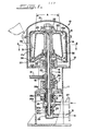
- a centrifugal separator 10 includes a base frame 11 and a casing 12 fixed to the top of the frame 11.
- the casing 12 has a top lid 13 hinged to it to be manually opened and closed, the open position of the lid 13 being shown in dash-dot-dot lines in Fig. 1.
- the lid 13 can be locked when in the closed position shown in solid lines.
- the casing 12 houses a cylindrical rotor or bucket 14 fixed coaxially and removably to the upper end of a vertical tubular drive shaft 15 which is journalled by two bearings 16 and 17 on the frame 11.
- the rotor 14 is rotated at a specific rate by an electric or hydraulic motor (not shown) through belts 19 connected to a pulley 18 fastened on the shaft 15.
- the rotor 14 houses a conical or tapered member 20 fixed to it, forming an annular or circumferential separation chamber 32 between the outer conical surface 20a of the member 20 and the inner cylindrical surface 14a of the rotor 14.
- the chamber 32 has inlet ports 22 formed at the lower center of the rotor 14, and outlet ports 23 at the upper center.
- the diameter of the conical surface 20a increases in the downward direction.
- the rotor 14 has a plurality of vertical ribs 21 fixed to the inner surface 14a.
- the hollow drive shaft 15 surrounds a pipe 28 which is fixed to it, forming an inner passage 28a inside the pipe 28, and an outer annular passage 24 around the pipe 28 and inside the shaft 15.
- the annular passage 24 communicates with the inlet ports 22, and the inner passage 28a communicates with the outlet ports 23.
- the lower end of the shaft 15 extends rotatably into an upper header 25 formed in the frame 11, so that the bottom of the annular passage 24 opens in the header 25.
- the lower end of the shaft is sealedoto the header with a rotary mechanical seal 26, which includes a seat ring 26a and a seal ring 26c urged against the seat ring 26a by a spring 26b.
- the header 25 has an inlet 27.
- the lower end of the pipe 28 extends rotatably through the lower side of the header 25 and into a lower header 29, which is mounted on the lower surface of the upper header 25, so that the inner passage 28a of the pipe 28 opens in the lower header 29.
- the lower end of the pipe is sealed to the lower header with a rotary mechanical seal 30, which includes a seat ring 30a and a seal ring 30c urged against the seat ring 30a by a spring 30b.
- the lower header 29 is connected to an outlet 31.
- waste water is supplied under pressure through the inlet 27, the upper header 25, the annular passage 24 and the ports 22 to the lower portion of the separation chamber 32 formed between the rotor 14 and the member 20. While flowing upwards (due to the inlet pressure) toward the outlet ports 23 inside the chamber 32, the water is subjected to the centrifugal force due to the rotation of the rotor 14 and the ribs 21, and the suspended substances in the waste water are precipitated and separated by being pressed onto the inner surface 14a. The water after separation passes through the outlet ports 23, inner passage 28a, lower header 29 and outlet 31, and is sent to a conventional oil densitometer (not shown).
- the lower ends of the shaft 15 and the pipe 28, which rotate with the rotor 14, are rotatable in the fixed headers 25 and 29, respectively, and hermetically sealed, making the entire route from the inlet 27 to the outlet 31 a hermetically sealed structure. This prevents any inflammable gas contained in the waste water from leaking out of the system.
- the water forced into the inlet 27 flows to the outlet 31 by its own pressure.
- the pressure of the water discharged from the outlet 31 is the pressure of the water fed to the inlet 27 less the pressure loss in moving through the separator.
- the water forced into the inlet 27 flows out of the outlet 31 even when rotation of the rotor 14 is halted. Therefore, if, after a separation process, cleaning water is forced into the inlet 27 even while the rotor 14 is not rotating, the cleaning water will flow through the rotor 14 and out of the outlet 31. This enables the suspended substances precipitated and separated on the inner rotor surface 14a to be washed away and removed.
- the cleaning water may be forced into the outlet 31 and discharged from the inlet 27.
- the lid 13 of the casing 12 may be swung open on the hinge as shown by the dash-dot-dot lines in Fig. 1, and the nut 33 fastening the rotor 14 to the drive shaft may be.removed to disassemble the rotor 14 and manually remove the suspended substances from the inside.
- the rotor 14 is formed by an upper inverted cup-shaped part 36 and a lower disk-shaped part 37, and the lower edge of the cup 36 fits into a groove 38 of the disk 37. Therefore after the nut 33 has been removed from the separator, the cup 36 may be lifted off the disk 37 to gain access to the interior of the cup.
- this surface 20a were not conical but cylindrical, when the oil gathered on the surface 20a moves up along the surface due to the difference in the specific gravities of oil and water and the water flow, the rate of adhesion to the surface 20a would increase, and the oil adhered to the surface 20a would move upward and be peeled off from the surface 20a after growing into large oil drops, thus delaying the flow of the oil from the chamber 32. In other words, the amount of time needed for the separation and removal of suspended substances would be prolonged by this action.
- the surface 20a is conical with a diameter that increases in the downward direction, as mentioned above. This reduces the amount of oil which adheres to the surface 20a when the oil gathered on it moves upward. Thus, the oil content introduced to the lower portion of the surface 20a promptly reaches the upper portion, successfully preventing the delay in the flow of oil content out of the chamber 32.
- the angle A (Fig. 1) of taper of the surface 20a should be large from the standpoint of shortening the time required for the discharge of the oil content.
- the interior volume of the-chamber 32 increases with an increase of the angle A, thus raising the volume of water pooled inside the chamber 32. Therefore, this angle should be within limits. From experiments, the preferred angle range has been found to be between 2 and 40 degrees, with the most advantageous angle being 10 degrees.
Landscapes
- Chemical & Material Sciences (AREA)
- Engineering & Computer Science (AREA)
- Environmental & Geological Engineering (AREA)
- Mechanical Engineering (AREA)
- Life Sciences & Earth Sciences (AREA)
- Hydrology & Water Resources (AREA)
- Water Supply & Treatment (AREA)
- Organic Chemistry (AREA)
- Analytical Chemistry (AREA)
- Physics & Mathematics (AREA)
- Thermal Sciences (AREA)
- Chemical Kinetics & Catalysis (AREA)
- Centrifugal Separators (AREA)
Applications Claiming Priority (4)
| Application Number | Priority Date | Filing Date | Title |
|---|---|---|---|
| JP119710/85 | 1985-08-02 | ||
| JP1985119710U JPS6227751U (de) | 1985-08-02 | 1985-08-02 | |
| JP59250/86 | 1986-04-18 | ||
| JP1986059250U JPH039803Y2 (de) | 1986-04-18 | 1986-04-18 |
Publications (3)
| Publication Number | Publication Date |
|---|---|
| EP0211616A2 true EP0211616A2 (de) | 1987-02-25 |
| EP0211616A3 EP0211616A3 (en) | 1988-06-08 |
| EP0211616B1 EP0211616B1 (de) | 1991-03-20 |
Family
ID=26400302
Family Applications (1)
| Application Number | Title | Priority Date | Filing Date |
|---|---|---|---|
| EP86305867A Expired - Lifetime EP0211616B1 (de) | 1985-08-02 | 1986-07-30 | Zentrifugalseparator, um Schlamm von Abwasser zu trennen |
Country Status (4)
| Country | Link |
|---|---|
| US (1) | US4724076A (de) |
| EP (1) | EP0211616B1 (de) |
| KR (1) | KR900000028B1 (de) |
| DE (1) | DE3678223D1 (de) |
Cited By (3)
| Publication number | Priority date | Publication date | Assignee | Title |
|---|---|---|---|---|
| EP0743096A3 (de) * | 1995-05-19 | 1997-12-03 | Domenico Manca | Apparat mit verringerten Abmessungen für die Zentrifugaltrennung |
| WO2011119088A1 (en) * | 2010-03-22 | 2011-09-29 | Alfa Laval Corporate Ab | Centrifugal separator |
| CN111991852A (zh) * | 2020-09-10 | 2020-11-27 | 天津市顺泽采油设备有限公司 | 一种石油采样检测快速分离泵 |
Families Citing this family (6)
| Publication number | Priority date | Publication date | Assignee | Title |
|---|---|---|---|---|
| US4882094A (en) * | 1988-02-26 | 1989-11-21 | Foster-Miller, Inc. | Separation system for dewatering radioactive waste materials |
| DE19809863C2 (de) * | 1998-03-07 | 2001-11-22 | Dorr Oliver Deutschland | Kontinuierlich arbeitende Zentrifuge |
| US6810365B1 (en) * | 2002-06-13 | 2004-10-26 | The United States Of America As Represented By The Secretary Of The Navy | Monitoring waste liquid to determine membrane cleansing performance |
| RU2317860C2 (ru) * | 2005-03-28 | 2008-02-27 | Общество с ограниченной ответственностью "Прогрессивные технологии в промышленности" | Осадительная центрифуга периодического действия |
| WO2009075440A1 (en) * | 2007-12-11 | 2009-06-18 | Fil Max Co., Ltd. | Filtering apparatus employing the rotor for multistage generating variable vortex flow |
| SE535275C2 (sv) | 2010-03-31 | 2012-06-12 | Alfa Laval Corp Ab | Centrifugalseparator och rotor |
Family Cites Families (6)
| Publication number | Priority date | Publication date | Assignee | Title |
|---|---|---|---|---|
| FR767977A (fr) * | 1933-04-21 | 1934-07-27 | Anciens Etablissements Cime | Séparateur centrifuge |
| GB1266496A (de) * | 1968-05-08 | 1972-03-08 | ||
| US3675846A (en) * | 1970-06-15 | 1972-07-11 | Bio Consultants Inc | Continuous flow centrifuge head construction |
| FR2410509A1 (fr) * | 1977-12-02 | 1979-06-29 | Hitachi Ltd | Extracteur centrifuge liquide-liquide |
| JPS617801A (ja) * | 1984-06-23 | 1986-01-14 | Canon Inc | 屈折率分布型レンズの製造方法及びその装置 |
| JPS6115968A (ja) * | 1984-06-29 | 1986-01-24 | Nec Corp | 真空蒸着装置 |
-
1986
- 1986-07-21 US US06/893,190 patent/US4724076A/en not_active Expired - Fee Related
- 1986-07-30 DE DE8686305867T patent/DE3678223D1/de not_active Expired - Fee Related
- 1986-07-30 EP EP86305867A patent/EP0211616B1/de not_active Expired - Lifetime
- 1986-08-01 KR KR1019860006368A patent/KR900000028B1/ko not_active Expired
Cited By (6)
| Publication number | Priority date | Publication date | Assignee | Title |
|---|---|---|---|---|
| EP0743096A3 (de) * | 1995-05-19 | 1997-12-03 | Domenico Manca | Apparat mit verringerten Abmessungen für die Zentrifugaltrennung |
| WO2011119088A1 (en) * | 2010-03-22 | 2011-09-29 | Alfa Laval Corporate Ab | Centrifugal separator |
| CN102892512A (zh) * | 2010-03-22 | 2013-01-23 | 阿尔法拉瓦尔股份有限公司 | 离心分离器 |
| CN102892512B (zh) * | 2010-03-22 | 2014-09-17 | 阿尔法拉瓦尔股份有限公司 | 离心分离器 |
| US9333516B2 (en) | 2010-03-22 | 2016-05-10 | Alfa Laval Corporate Ab | Centrifugal separator having a support element and bearing around portions of a spindle |
| CN111991852A (zh) * | 2020-09-10 | 2020-11-27 | 天津市顺泽采油设备有限公司 | 一种石油采样检测快速分离泵 |
Also Published As
| Publication number | Publication date |
|---|---|
| EP0211616A3 (en) | 1988-06-08 |
| EP0211616B1 (de) | 1991-03-20 |
| KR870001873A (ko) | 1987-03-28 |
| DE3678223D1 (de) | 1991-04-25 |
| KR900000028B1 (ko) | 1990-01-18 |
| US4724076A (en) | 1988-02-09 |
Similar Documents
| Publication | Publication Date | Title |
|---|---|---|
| US6248053B1 (en) | Centrifugal separator comprising tubular elements | |
| US4724076A (en) | Centrifugal separator for separating sludge in waste water | |
| EP0879091B1 (de) | Feststoffabstreifer für eine zentrifuge | |
| US5149432A (en) | Centrifuge for separating liquids of different specific gravities | |
| FR2520258A1 (fr) | Extracteur centrifuge a contre-courant a enveloppe continue, fonctionnant en continu | |
| US4406651A (en) | Multi-phase self purging centrifuge | |
| US6030332A (en) | Centrifuge system with stacked discs attached to the housing | |
| US4961724A (en) | Low speed particle concentrators | |
| SU1044223A3 (ru) | Осадительна центрифуга дл разделени двухфазной жидкой смеси,содержащей твердую фракцию | |
| RU2283188C2 (ru) | Шнековая центрифуга со сплошным ротором, содержащая срезающий диск, и способ ее эксплуатации | |
| US3321131A (en) | Centrifuge | |
| US4774008A (en) | Apparatus for separating a mixture into solid and liquid components | |
| US4184959A (en) | Sludge recovery apparatus | |
| US5823937A (en) | Low-shear feeding system for use with centrifuges | |
| US5674174A (en) | Low-shear feeding system for use with bottom feed centrifuges | |
| SU1071212A3 (ru) | Центрифуга дл разделений суспензий | |
| CA1233445A (en) | Centrifugal separator | |
| WO1997016256A9 (en) | Low-shear centrifuge feeding system | |
| GB1569520A (en) | Solid bowl screw centrifuges | |
| EP0164866A1 (de) | Aufrechterhaltung des Flüssigkeitspegels in einem Zentrifugen-Separator | |
| US4065393A (en) | Conical centrifuge with continuous action | |
| US1895104A (en) | Apparatus for separation | |
| JPH039803Y2 (de) | ||
| GB2121325A (en) | Cleaning centrifuge | |
| GB2115319A (en) | Centrifuge and method of operating same |
Legal Events
| Date | Code | Title | Description |
|---|---|---|---|
| PUAI | Public reference made under article 153(3) epc to a published international application that has entered the european phase |
Free format text: ORIGINAL CODE: 0009012 |
|
| 17P | Request for examination filed |
Effective date: 19860807 |
|
| AK | Designated contracting states |
Kind code of ref document: A2 Designated state(s): DE FR GB NL SE |
|
| PUAL | Search report despatched |
Free format text: ORIGINAL CODE: 0009013 |
|
| AK | Designated contracting states |
Kind code of ref document: A3 Designated state(s): DE FR GB NL SE |
|
| 17Q | First examination report despatched |
Effective date: 19880915 |
|
| GRAA | (expected) grant |
Free format text: ORIGINAL CODE: 0009210 |
|
| AK | Designated contracting states |
Kind code of ref document: B1 Designated state(s): DE FR GB NL SE |
|
| REF | Corresponds to: |
Ref document number: 3678223 Country of ref document: DE Date of ref document: 19910425 |
|
| ET | Fr: translation filed | ||
| PLBE | No opposition filed within time limit |
Free format text: ORIGINAL CODE: 0009261 |
|
| STAA | Information on the status of an ep patent application or granted ep patent |
Free format text: STATUS: NO OPPOSITION FILED WITHIN TIME LIMIT |
|
| 26N | No opposition filed | ||
| PGFP | Annual fee paid to national office [announced via postgrant information from national office to epo] |
Ref country code: FR Payment date: 19920707 Year of fee payment: 7 |
|
| PGFP | Annual fee paid to national office [announced via postgrant information from national office to epo] |
Ref country code: SE Payment date: 19920713 Year of fee payment: 7 |
|
| PGFP | Annual fee paid to national office [announced via postgrant information from national office to epo] |
Ref country code: GB Payment date: 19920717 Year of fee payment: 7 |
|
| PGFP | Annual fee paid to national office [announced via postgrant information from national office to epo] |
Ref country code: DE Payment date: 19920727 Year of fee payment: 7 |
|
| PGFP | Annual fee paid to national office [announced via postgrant information from national office to epo] |
Ref country code: NL Payment date: 19920731 Year of fee payment: 7 |
|
| PG25 | Lapsed in a contracting state [announced via postgrant information from national office to epo] |
Ref country code: GB Effective date: 19930730 |
|
| PG25 | Lapsed in a contracting state [announced via postgrant information from national office to epo] |
Ref country code: SE Effective date: 19930731 |
|
| PG25 | Lapsed in a contracting state [announced via postgrant information from national office to epo] |
Ref country code: NL Effective date: 19940201 |
|
| NLV4 | Nl: lapsed or anulled due to non-payment of the annual fee | ||
| GBPC | Gb: european patent ceased through non-payment of renewal fee |
Effective date: 19930730 |
|
| PG25 | Lapsed in a contracting state [announced via postgrant information from national office to epo] |
Ref country code: FR Effective date: 19940331 |
|
| PG25 | Lapsed in a contracting state [announced via postgrant information from national office to epo] |
Ref country code: DE Effective date: 19940401 |
|
| REG | Reference to a national code |
Ref country code: FR Ref legal event code: ST |
|
| EUG | Se: european patent has lapsed |
Ref document number: 86305867.3 Effective date: 19940210 |