EP0211701A1 - Drehschwingungsdämpfer, insbesondere für Kraftfahrzeugkupplung, wobei die Dämpfung wenigstens teilweise durch ein Elastomerelement erzeugt wird - Google Patents
Drehschwingungsdämpfer, insbesondere für Kraftfahrzeugkupplung, wobei die Dämpfung wenigstens teilweise durch ein Elastomerelement erzeugt wird Download PDFInfo
- Publication number
- EP0211701A1 EP0211701A1 EP86401276A EP86401276A EP0211701A1 EP 0211701 A1 EP0211701 A1 EP 0211701A1 EP 86401276 A EP86401276 A EP 86401276A EP 86401276 A EP86401276 A EP 86401276A EP 0211701 A1 EP0211701 A1 EP 0211701A1
- Authority
- EP
- European Patent Office
- Prior art keywords
- hub
- elastic means
- washer
- rotation
- integral
- Prior art date
- Legal status (The legal status is an assumption and is not a legal conclusion. Google has not performed a legal analysis and makes no representation as to the accuracy of the status listed.)
- Granted
Links
- 238000013016 damping Methods 0.000 title claims abstract description 13
- 229920001971 elastomer Polymers 0.000 claims abstract description 22
- 239000000806 elastomer Substances 0.000 claims abstract description 22
- 230000002093 peripheral effect Effects 0.000 claims description 7
- 239000013536 elastomeric material Substances 0.000 claims description 4
- 229910052751 metal Inorganic materials 0.000 claims description 4
- 241000826860 Trapezium Species 0.000 claims description 3
- 239000002184 metal Substances 0.000 claims description 3
- 230000006835 compression Effects 0.000 claims description 2
- 238000007906 compression Methods 0.000 claims description 2
- 230000000712 assembly Effects 0.000 claims 1
- 238000000429 assembly Methods 0.000 claims 1
- 206010052904 Musculoskeletal stiffness Diseases 0.000 description 21
- 238000006073 displacement reaction Methods 0.000 description 8
- 239000002131 composite material Substances 0.000 description 4
- 230000008878 coupling Effects 0.000 description 3
- 238000010168 coupling process Methods 0.000 description 3
- 238000005859 coupling reaction Methods 0.000 description 3
- 125000006850 spacer group Chemical group 0.000 description 3
- 241001272720 Medialuna californiensis Species 0.000 description 2
- 241000030366 Scorpidinae Species 0.000 description 2
- 230000004308 accommodation Effects 0.000 description 2
- 230000005540 biological transmission Effects 0.000 description 2
- 238000010276 construction Methods 0.000 description 2
- 238000004519 manufacturing process Methods 0.000 description 2
- 239000000463 material Substances 0.000 description 2
- 238000012856 packing Methods 0.000 description 2
- 230000006978 adaptation Effects 0.000 description 1
- 230000001174 ascending effect Effects 0.000 description 1
- 230000000295 complement effect Effects 0.000 description 1
- 239000000470 constituent Substances 0.000 description 1
- 230000036461 convulsion Effects 0.000 description 1
- 238000013213 extrapolation Methods 0.000 description 1
- 238000001914 filtration Methods 0.000 description 1
- 238000007373 indentation Methods 0.000 description 1
- 238000012886 linear function Methods 0.000 description 1
- 238000000034 method Methods 0.000 description 1
- 230000007935 neutral effect Effects 0.000 description 1
- 230000000750 progressive effect Effects 0.000 description 1
- 230000002787 reinforcement Effects 0.000 description 1
- 230000000284 resting effect Effects 0.000 description 1
- 230000035939 shock Effects 0.000 description 1
- 238000004073 vulcanization Methods 0.000 description 1
Images


Classifications
-
- F—MECHANICAL ENGINEERING; LIGHTING; HEATING; WEAPONS; BLASTING
- F16—ENGINEERING ELEMENTS AND UNITS; GENERAL MEASURES FOR PRODUCING AND MAINTAINING EFFECTIVE FUNCTIONING OF MACHINES OR INSTALLATIONS; THERMAL INSULATION IN GENERAL
- F16D—COUPLINGS FOR TRANSMITTING ROTATION; CLUTCHES; BRAKES
- F16D13/00—Friction clutches
- F16D13/58—Details
- F16D13/60—Clutching elements
- F16D13/64—Clutch-plates; Clutch-lamellae
- F16D13/68—Attachments of plates or lamellae to their supports
- F16D13/686—Attachments of plates or lamellae to their supports with one or more intermediate members made of rubber or like material transmitting torque from the linings to the hub
-
- F—MECHANICAL ENGINEERING; LIGHTING; HEATING; WEAPONS; BLASTING
- F16—ENGINEERING ELEMENTS AND UNITS; GENERAL MEASURES FOR PRODUCING AND MAINTAINING EFFECTIVE FUNCTIONING OF MACHINES OR INSTALLATIONS; THERMAL INSULATION IN GENERAL
- F16F—SPRINGS; SHOCK-ABSORBERS; MEANS FOR DAMPING VIBRATION
- F16F15/00—Suppression of vibrations in systems; Means or arrangements for avoiding or reducing out-of-balance forces, e.g. due to motion
- F16F15/10—Suppression of vibrations in rotating systems by making use of members moving with the system
- F16F15/12—Suppression of vibrations in rotating systems by making use of members moving with the system using elastic members or friction-damping members, e.g. between a rotating shaft and a gyratory mass mounted thereon
- F16F15/121—Suppression of vibrations in rotating systems by making use of members moving with the system using elastic members or friction-damping members, e.g. between a rotating shaft and a gyratory mass mounted thereon using springs as elastic members, e.g. metallic springs
- F16F15/124—Elastomeric springs
Definitions
- the present invention relates, in general, to torsion damping devices, in particular for clutches of motor vehicles, which comprise at least three coaxial elements, namely a driven hub, a hub plate driving the latter in rotation with play, and a drive assembly comprising a packing disk, these coaxial elements being mounted to rotate relative to each other against elastic means having at least two levels of stiffness, and for at least two sectors of limited determined angular deflections by angular strokes between meshing means.
- This drive means is, in many cases, constituted by at least one axial spacer, most often a spacer between the lining-carrying disk of which it is integral and a rotary element thus secured in rotation with the latter and is maintained axially at a determined distance.
- the two abutment means determining the circumferential angular displacement of each baluster, consist of the substantially radial edges of a notch formed in rotary elements, the hub veil for example, being axially interposed between the packing disc and said rotary element integral with this one.
- a second type of so-called secondary engagement means consists of the engagement of two concentric teeth means having a determined angular play .
- the displacement relative to the driven part that is to say the hub, takes place beyond these limits in a second phase against the main elastic means , of greater stiffness which, given their stiffness relative to that of the secondary elastic means, behave like a rigid block during the first phase.
- the advantage presented by a torsion damping device with two successive stages of stiffness is to allow greater progressiveness than that presented by a single stage of stiffness, that is to say using only one kind of elastic means.
- the elastic means are coil springs arranged circumferentially in windows provided for this purpose in the various rotary elements used.
- the springs have a linear function (displacement / force). This implies that the function determined by the behavior of such a device, expressed in terms of (angular travel / torque), has thresholds, determining linear operating ranges.
- the object of the present invention is a device torsion damper having a desirable progressiveness of operation without implying the above-mentioned drawbacks.
- a torsional damping device in particular for the clutch of a motor vehicle, of the type comprising at least three coaxial parts, a drive, an intermediate and a driven, rotatably mounted relative to each other within the limits of an angular displacement determined by means of engagement with clearance provided for this purpose between said coaxial parts, and against first and second elastic means with circumferential action, capable of acting circumferentially between them for two ranges at least angular deflections determined by means of engagement with clearance provided for this purpose between said coaxial parts, means for securing in rotation a first group of elements of the driving part, group comprising a friction disc and at at least one support and centering element thereof, with a guide washer one of the faces of which is integral in rotation with an annular element made of elas material tomer whose opposite radial face is integral in rotation with said intermediate coaxial part, characterized in that said annular elastomer element has an at least partially trapezoidal cross section inside, the small base of the trapezium
- the present invention also relates to a hub web assembly for a torsion damper in a motor vehicle clutch, characterized in that it comprises at least one annular elastomer element constituting a first elastic means with circumferential action and in that it meshes with play, to against a second elastic means with circumferential action, interposed between the hub web and said driven part which is a hub.
- such a hub web assembly is characterized in that it consists of at least two hub webs arranged coaxially at an axial distance from one another, said webs of hub being connected to each other by at least one annular elastomer element, in that a first hub wall is integral in rotation with the lining-carrier disc, and in that a second hub wall is integral in rotation with a concentric guide washer, the two hub webs meshing the hub 'by toothing means having different clearances.
- a hub plate assembly according to the invention comprises three separate hub plates between which two annular elastomer elements are interposed, the hub plate being in the intermediate position being a flat disc defining a plane of symmetry axial of said assembly and the three hub webs mesh the hub by toothing means having different clearances.
- said second elastic means are coil springs.
- said second elastic means are blocks of elastomeric material.
- said second elastic means and said first elastic means consist of a single annular elastomer element having axial projections near its internal diameter, said projections constituting said first elastic means.
- a particular advantage of the present invention over the prior art is the improvement in reliability hub sails. Indeed, these, in conventional torsional damping devices, are cut out of windows which necessarily weaken them.
- the annular elastomer element introduces non-linearity in the transmission of the torque, due to the internal losses specific to the material.
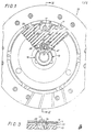
- the assembly of the device according to the invention bears the general reference 10 and comprises, as shown in FIGS. 1, 2, 3 and 4 a lining-carrying veil 11 integral in rotation and coaxial with a support flange 16, itself integral in rotation with a bearing 14 free to rotate around a hub 13 of which it surrounds one of the ends.
- the lining-carrying disc 11 constitutes a ring whose radially internal marginal zone is superimposed with a peripheral zone of the flange 16, thus establishing an annular radial contact surface.
- the three balusters, equidistant from a general axis 12 of the device according to the invention, are distributed at 120 * and pass through the flange and the lining carrier disc which they secure in forming a rivet.
- balusters 17, opposite the lining carrier disc also form a rivet, and secure a guide washer 18 and a so-called adhesion flange 19.
- the washer 18 and the flange 19 have a flat annular peripheral zone by which they are secured, with the heads of the balusters 17, which pass through them in this zone, extended by a tapered internal radial zone.
- the tapered internal radial zone of the flange 18 extends until it reaches a bearing 15, with which it is integral in rotation.
- the bearing 15 is free to rotate around the hub 13.
- the flange 19, radially less extended inwards than the washer 18, does not join the bearing 15.
- the washer 18 and the flange 19 are generally frustoconical, with the exception, however, of an axial recession 18 'and 19' respectively.
- recessions exactly overlap, extend in a plane normal to the axis of the balusters 17, and are located around the end of the latter.
- the role of such recessions is to provide a surface for fixing the heads of the balusters 17 normal to the axis of each of them, to allow riveting in good conditions.
- the guide washer 18 and the adhesion flange 19 fit together and are joined in rotation.
- the rotational connection of the bearing 15 and the washer 18 is effected by meshing three radial projections in the form of half-moons arranged 120 * from the bearing with three corresponding recesses provided for this purpose in the guide washer.
- a Belleville washer 20 rests on the guide washer 18 and exerts an axial pressure on the bearing 15 which it meshes with the same projections in half-moons.
- the cross section of the bearing 15 is generally L-shaped, the part axially located in mesh with the washer 18 having the smallest external diameter.
- the half-moon projections catch up with the largest external diameter of the bearing.
- the washer 14 meshes the flange 16 by three projections in half-moon in an identical manner.
- the bearings 14 and 15 are made of composite material.
- the washer 18 can be omitted, the flange 19 having in this case an axial flange while the bearing 15 is carried by a flange with an axial flange linked to the axial flange of the flange 19.
- annular element made of elastomeric material 22 is integral with the adhesion flange 19, on the one hand, and a hub plate 23 on the other hand.
- the annular element 22 follows by its two radial faces the adhesion flange 19 and the hub plate 23, to which it is secured by adhesion, a method known per se making it possible to secure a metallic element and a composite element, in elastomer, for example, during the vulcanization of the latter.
- the end of the flange 19 is situated on a circumference of diameter greater than the internal diameter, which facilitates the passage of a tool and makes it possible to vulcanize the element 22 on the hub veil and the flange without burr to form a subset.
- the hub cover 23 being a flat metal disc, the annular element 22 comprises a first peripheral zone delimited axially by the hub cover on the one hand, and by the planar peripheral area, parallel to the hub cover, of the flange grip 19, on the other hand.
- this first zone are formed three notches 24 extending over a radial height and a circumferential width allowing a circumferential movement of the balusters 17 in notches.
- the radial edges 25 of notches thus constitute stops which therefore limit the circumferential movement of these posts.
- the annular element 22 has, from the notches 24, axially projecting flanges which match and cover the edge of the edges of the notches 26 of the hub cover.
- the annular element 22 has a second concentric zone radially inside the first, of trapezoidal section, the small base of the trapezium being closest to the axis 12.
- the annular element 22 follows the shape of the washer 18 and the flange.
- This trapezoidal section is delimited by, on one side, the flat hub cover, and on the other side by the frustoconical part of the adhesion flange 19.
- the radial extent of the annular element 22 is identical to that of the flange 19 and its internal circumference of the element 22 is radially spaced from the hub plate 13 which it surrounds and more inside than that of said flange 19 .
- the annular element 22 is made of composite elastomer, of which a fibrous reinforcement is arranged circumferentially.
- the hub plate 23 is provided, at its internal circumference, with a toothing 27 which meshes with a corresponding toothing 28 of complementary configuration formed at the periphery of a radial projection 29 or flange of the hub 13, this gear comprising a determining circumferential clearance an angular clearance between the hub plate 23 and the hub 13.
- Denial windows 31.30 arranged circumferentially opposite in the radial projection 29 of the hub 13 and on the internal circumference of the hub web 23, constitute, when they are aligned, a window whose radial orientation edges draw the two halves with an X, the or each window thus formed housing a coil spring 32 disposed circumferentially and opposed, by compression of said spring 32 between an edge of the half-window 30 of the hub web 23 and an edge of the half window 31 of the hub 13, at any angular movement between the hub web and the hub.
- the lining carrier 11, the support flange 16, the columns 17, the guide washer 18, the adhesion flange 19 as well as the bearings 14 and 15 are therefore integral in rotation. Overall, all of these elements constitute a leading part.
- the hub cover 23 constitutes an intermediate part.
- the hub 13 constitutes a driven part.
- the annular elastomer element 22 integral by one of its radial faces with the driving part, transmits a torque, printed on this part by circumferential shear force, to the intermediate part, that is to say the web hub 23 of which it is integral by its other radial face.
- the element 22 therefore constitutes a first elastic means with circumferential action.
- This elastic means is opposed to the angular movement between the columns 17 of the driving part and the stops 25 of the notches 24 of the annular element 22 superimposed on the notches 26 of the hub web 23, the notches and the columns constituting means of meshing of the driving part with the intermediate part.
- the hub web 23 meshes with play on the hub 13, that is to say the driven part, an angular clearance between these two parts being against the springs 32.
- the springs 32 constitute a second elastic means with circumferential action of lower stiffness, in particular for good filtration of idle noise.
- a hub cover assembly comprises, in this embodiment, a guide washer 18, an adhesion flange 19, a first elastic means constituted by an annular element 22, a hub cover 23, and a second elastic means consisting of springs 32 arranged circumferentially and partially in half-windows 30 of the hub web.
- the hub web assembly as a whole, comprising at least two elastic means.
- the first elastic means offer a stiffness greater than that of the second elastic means by being arranged radially above the second means.
- the second elastic means compress until the teeth come into abutment meshing with the hub and the hub plate.
- the coupling in this case, becomes direct until the relative torque is weakened.
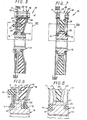
- Figures 5 and 6 show an alternative embodiment of the invention in which a support washer 33, provided with axial projections 34 substantially cylindrical on one of its faces, is pressed against the face of the remaining hub plate 23 free by an elastic washer 35, for example of the Belleville wavy washer type, the latter being supported on the flange 16.
- a support washer 33 provided with axial projections 34 substantially cylindrical on one of its faces, is pressed against the face of the remaining hub plate 23 free by an elastic washer 35, for example of the Belleville wavy washer type, the latter being supported on the flange 16.
- the protrusions 34 penetrate into orifices provided for this purpose in the flange 16 with sufficient clearance to allow relative axial movement between the support washer 33 and the flange 16 while securing them in rotation.
- the support washer 33 is made of composite material, and presses on a friction washer 36 integral in rotation with the hub 13.
- a hub wall assembly comprises two substantially identical hub walls 23 and 23 ′ arranged opposite one another and each having a zone peripheral in the form of a flat disc, a frustoconical intermediate zone, and an internal marginal zone in the form of a flat disc.
- An annular elastomer element 22 is interposed and adhered to the two opposite faces of the two hub webs which mesh with two different levels of play on a radial projection 29 of the hub 13.
- the hub cover 23 is secured by riveting to the flat carrier disc 11, directly mounted integral in rotation with the bearing 14, free to rotate around one end of the hub 13.
- the second hub wall 23 ' secured by riveting to a flat guide washer 18, which meshes with a bearing pushed axially by a Belleville washer resting on the guide washer 18 and by means of a washer d the support, as described above, is capable of abutting against the radial projection 29.
- the angular travel between the hub web 23 and the hub 13 is less than the angular travel between the hub web 23 'and the hub.
- Female teeth 30 (FIG. 9) formed in the hub cover 23 and larger female teeth 32 formed in the hub cover 23 ′ mesh with male teeth in the radial projection 29 of the hub.
- half-windows formed in the hub wall 23 and in the projection 29 of the hub are arranged opposite, so as to receive elastic means called second means.
- the two hub webs 23 and 23 ′ can be identical, the teeth 30 and 32 then being identical, while the male teeth of the radial projection 29 of the hub are different.
- these second elastic means consist of blocks known as "X" substantially parallelepiped, with lateral notches in obtuse angle, giving an aspect of X.
- these blocks X are in elaxromere.
- the elastomeric annular element 22 constitutes the first elastic means, of greater stiffness by its radial position and its radial extent, than the second elastic means.
- Figures 10 and 11 show another alternative embodiment comprising three different angular deflections, and three different levels of stiffness.
- the hub web assembly comprises three concentric hub webs 23, 23 ', 23 ", arranged axially separated by two elastomeric annular elements 22 and 22'.
- a first hub web 23 is integral with the lining carrier disc 11 and the support flange 16 having an axial offset towards the outside.
- This hub cover is adhered to a first elastomeric annular element 22, having, as in the first embodiment described, a peripheral part of rectangular cross section and an internal part of trapezoidal section.
- the first hub wall 23 is of a shape adapted to match a first radial face of this annular element 22.
- the second hub wall 23 ' is a flat disc disposed axially in the middle position to which the two flat faces of the elements 22 and 22' are adhered.
- the second elastomeric annular element 22 ′ is substantially identical to the first 22.
- the third hub plate 23 is symmetrical with respect to the plane of the second hub plate 23 'of the first hub plate 23, of which it also has the shape.
- the hub webs 23, 23 ′, 23 "all mesh with female teeth with male teeth of the radial projection 29 of the hub web, with three different angular deflections, going through Ascending .
- the elastomeric elements 22 and 22 ' after saturation of the first elastic means, tend to oppose the residual angular movement between the second hub web 23' and the hub. They thus constitute a second elastic means.
- Notches made in the first and second hub webs allow the passage of small columns 17 which join the lining carrier disc 11, the support flange 16 and the third hub web 23 ".
- FIG. 11 schematically represents the different angular deflections between the three hub webs 23, 23 ', 23 "and the radial projection of the hub 29, of which only one tooth 28 is shown.
- the circumferential travel of the balusters, between the radial edges of the notches forming a stop determines the possible angular travel between the successive hub webs.
- the supports of the hub web assembly thus formed around the hub are bearings 14 and 15, similar to those used in the embodiments described above.
- FIGS 12 and 13 show another alternative embodiment of the invention, in which a hub plate 23 called “main”, planar, is arranged opposite a hub plate 23 'said “secondary”, of form partially frustoconical, and partially planar, as described above in the other embodiments, these webs being separated by an annular elastomer element 22 adhered on its two faces to the two hub webs.
- the secondary hub cover 23 ′ is secured by means of three columns 17 of the lining carrier disc 11.
- the elastomeric annular element 22 has notches at its periphery, as well as the main hub web 23, notches allowing a circumferential deflection of the balusters 17, and the edges of which are covered with edges projecting axially from the element 22, similar to that set out in the description of the first variant of the invention.
- the main hub cover 23 meshes by toothing arranged at its internal circumference with a corresponding toothing of the hub, as described above.
- facing half-windows cooperate in order to form windows capable of receiving second elastic means.
- the second elastic means are X-shaped blocks constituted by axial projections 33 of the annular elastomer element 22, also and mainly forming the first elastic means.
- the first and second elastic means are provided by a single constituent element, namely the annular elastomer element 22, which is in this case provided with projections.
- this alternative embodiment of the invention which in particular allows, like the second alternative embodiment described, to obtain good progressiveness of the action of the two elastic means, both being made from elastomer elements, allows the use of conventional parts, namely conventional hub sheets.
- the invention is not limited, of course, to the variant embodiments described, but includes in particular any combination of the various particularities described, any extrapolation, in particular the multiplicity of elastic means, as well as any adaptation or improvement which would be deemed useful by the invention. skilled in the art.
Landscapes
- Engineering & Computer Science (AREA)
- General Engineering & Computer Science (AREA)
- Mechanical Engineering (AREA)
- Physics & Mathematics (AREA)
- Acoustics & Sound (AREA)
- Aviation & Aerospace Engineering (AREA)
- Mechanical Operated Clutches (AREA)
Applications Claiming Priority (2)
| Application Number | Priority Date | Filing Date | Title |
|---|---|---|---|
| FR8509017 | 1985-06-14 | ||
| FR8509017A FR2583486B1 (fr) | 1985-06-14 | 1985-06-14 | Dispositif amortisseur de torsion, notamment pour embrayage de vehicule automobile, a amortissement au moins partiellement du a un element elastomere |
Publications (3)
| Publication Number | Publication Date |
|---|---|
| EP0211701A1 true EP0211701A1 (de) | 1987-02-25 |
| EP0211701B1 EP0211701B1 (de) | 1989-10-04 |
| EP0211701B2 EP0211701B2 (de) | 1994-06-22 |
Family
ID=9320234
Family Applications (1)
| Application Number | Title | Priority Date | Filing Date |
|---|---|---|---|
| EP86401276A Expired - Lifetime EP0211701B2 (de) | 1985-06-14 | 1986-06-12 | Drehschwingungsdämpfer, insbesondere für Kraftfahrzeugkupplung, wobei die Dämpfung wenigstens teilweise durch ein Elastomerelement erzeugt wird |
Country Status (5)
| Country | Link |
|---|---|
| US (1) | US4763767A (de) |
| EP (1) | EP0211701B2 (de) |
| JP (1) | JPS61286617A (de) |
| DE (1) | DE3666082D1 (de) |
| FR (1) | FR2583486B1 (de) |
Cited By (1)
| Publication number | Priority date | Publication date | Assignee | Title |
|---|---|---|---|---|
| FR2757230A1 (fr) * | 1996-12-13 | 1998-06-19 | Valeo | Dispositif d'accouplement elastique en rotation, notamment pour disque d'embrayage a friction |
Families Citing this family (23)
| Publication number | Priority date | Publication date | Assignee | Title |
|---|---|---|---|---|
| DE3621143A1 (de) * | 1986-06-24 | 1988-01-07 | Clouth Gummiwerke Ag | Drehschwingungstilger, insbesondere fuer getriebe von kraftfahrzeugen |
| FR2603083B1 (fr) * | 1986-08-21 | 1988-10-28 | Valeo | Dispositif amortisseur de torsion pour systeme de transmission de couple |
| FR2605695B2 (fr) * | 1986-08-21 | 1990-01-12 | Valeo | Dispositif amortisseur de torsion pour systeme de transmission de couple |
| FR2603081B1 (fr) * | 1986-08-21 | 1989-11-24 | Valeo | Dispositif amortisseur de torsion pour systeme de transmission de couple |
| FR2624939B1 (fr) * | 1987-12-16 | 1990-04-27 | Valeo | Dispositif amortisseur de torsion |
| DE3921283A1 (de) * | 1989-02-08 | 1990-08-09 | Fichtel & Sachs Ag | Kupplungsscheibe mit torsionsschwingungsdaempfer und radial elastischer lagerung |
| FR2645231B1 (fr) * | 1989-03-31 | 1993-01-22 | Valeo | Dispositif amortisseur de torsion, notamment friction d'embrayage pour vehicules automobiles |
| US4944279A (en) * | 1989-04-14 | 1990-07-31 | Eaton Corporation | Supercharger torsion damping mechanism with friction damping |
| FR2663707B1 (fr) * | 1990-06-22 | 1993-04-30 | Valeo | Dispositif amortisseur de torsion, notamment pour disque de friction d'embrayage de vehicule automobile. |
| DE9114585U1 (de) * | 1991-11-23 | 1992-02-06 | Fichtel & Sachs Ag, 8720 Schweinfurt | Kupplungsscheibe mit Kunststoffring |
| DE4140643C2 (de) * | 1991-12-10 | 1999-12-16 | Mannesmann Sachs Ag | Kupplungsscheibe mit elastischer Zentrierung |
| DE9212203U1 (de) * | 1992-09-10 | 1992-11-19 | Fichtel & Sachs Ag, 8720 Schweinfurt | Kupplungsscheibe mit radial elastischem Kunststoffring |
| ES2068773B1 (es) * | 1992-12-08 | 1998-12-16 | Fichtel & Sachs Ag | Disco de embrague con anillo de friccion protegido contra torsion. |
| US5573462A (en) * | 1993-12-06 | 1996-11-12 | Lord Corporation | Flexible dual-rate coupling |
| DE19531201A1 (de) * | 1995-08-24 | 1997-02-27 | Sgf Gmbh & Co Kg | Schwingungsdämpfendes torsionselastisches Wellengelenk, insbesondere für den Antriebsstrang von Kraftfahrzeugen |
| DE19714420A1 (de) * | 1997-04-08 | 1998-10-29 | Hackforth Gmbh & Co Kg | Wellenkupplung |
| DE19821948C2 (de) * | 1998-05-15 | 2003-11-27 | Hackforth Gmbh & Co Kg | Elastische Wellenkupplung |
| DE10017801B4 (de) * | 2000-04-10 | 2012-11-08 | Zf Sachs Ag | Torsionsschwingungsdämpfer |
| US20060223640A1 (en) * | 2005-04-05 | 2006-10-05 | Bassett Michael L | Rotational coupling with overload protection |
| DE102014016798A1 (de) * | 2014-11-14 | 2016-05-19 | Centa-Antriebe Kirschey Gmbh | Vorrichtung zur Übertragung von Drehmomenten u.a. |
| AT516751B1 (de) * | 2015-02-03 | 2016-08-15 | Tectos Gmbh | Drehelastische wellenkupplung |
| US9970488B2 (en) | 2015-04-30 | 2018-05-15 | Ace Manufacturing And Parts Co. | Clutch disc with resiliently deformable damping web and method of manufacturing same |
| JP6708004B2 (ja) * | 2016-06-20 | 2020-06-10 | アイシン精機株式会社 | ダンパ装置 |
Citations (5)
| Publication number | Priority date | Publication date | Assignee | Title |
|---|---|---|---|---|
| US2299029A (en) * | 1940-02-14 | 1942-10-13 | Borg Warner | Friction clutch |
| DE2639661A1 (de) * | 1976-09-03 | 1978-03-09 | Porsche Ag | Kupplungsscheibe |
| GB2068508A (en) * | 1980-02-06 | 1981-08-12 | Freudenberg C | Vibration-damping clutch discs |
| FR2493447A1 (fr) * | 1980-11-03 | 1982-05-07 | Valeo | Dispositif amortisseur de torsion, en particulier friction d'embrayage pour vehicule automobile |
| FR2494795A1 (fr) * | 1980-11-25 | 1982-05-28 | Valeo | Dispositif amortisseur de torsion notamment pour disque de friction d'embrayage de vehicule automobile |
Family Cites Families (7)
| Publication number | Priority date | Publication date | Assignee | Title |
|---|---|---|---|---|
| US2118913A (en) * | 1934-11-24 | 1938-05-31 | Autocar Company | Power transmitting mechanism |
| US2556624A (en) * | 1947-01-31 | 1951-06-12 | Macbeth | Resilient clutch plate |
| DE1425260A1 (de) * | 1962-12-05 | 1968-10-17 | Fichtel & Sachs Ag | Kupplungsscheibe mit einem aus Gummielementen aufgebauten Torsionsschwingungsdaempfer |
| IT1030414B (it) * | 1975-03-24 | 1979-03-30 | Automobili Torino Spa Fab | Disco per innesti a frizione |
| FR2496210A1 (fr) * | 1980-12-16 | 1982-06-18 | Valeo | Dispositif amortisseur de torsion, notamment pour disque de friction d'embrayage de vehicule automobile |
| JPH0245050B2 (ja) * | 1981-06-23 | 1990-10-08 | Aisin Seiki | Tadantooshonkuratsuchideisuku |
| US4588773A (en) * | 1984-12-21 | 1986-05-13 | Borg-Warner Chemicals, Inc. | Antistatic thermoplastic composition |
-
1985
- 1985-06-14 FR FR8509017A patent/FR2583486B1/fr not_active Expired
-
1986
- 1986-06-12 EP EP86401276A patent/EP0211701B2/de not_active Expired - Lifetime
- 1986-06-12 DE DE8686401276T patent/DE3666082D1/de not_active Expired
- 1986-06-14 JP JP61139109A patent/JPS61286617A/ja active Pending
- 1986-06-16 US US06/875,237 patent/US4763767A/en not_active Expired - Lifetime
Patent Citations (5)
| Publication number | Priority date | Publication date | Assignee | Title |
|---|---|---|---|---|
| US2299029A (en) * | 1940-02-14 | 1942-10-13 | Borg Warner | Friction clutch |
| DE2639661A1 (de) * | 1976-09-03 | 1978-03-09 | Porsche Ag | Kupplungsscheibe |
| GB2068508A (en) * | 1980-02-06 | 1981-08-12 | Freudenberg C | Vibration-damping clutch discs |
| FR2493447A1 (fr) * | 1980-11-03 | 1982-05-07 | Valeo | Dispositif amortisseur de torsion, en particulier friction d'embrayage pour vehicule automobile |
| FR2494795A1 (fr) * | 1980-11-25 | 1982-05-28 | Valeo | Dispositif amortisseur de torsion notamment pour disque de friction d'embrayage de vehicule automobile |
Non-Patent Citations (2)
| Title |
|---|
| PATENT ABSTRACTS OF JAPAN, vol. 7, no. 74 (M-203)[1219], 26 mars 1983; & JP-A-58 000 631 (AISHIN SEIKI K.K.) 05-01-1983 * |
| PATENTS ABSTRACTS OF JAPAN, vol. 7, no. 74 (M-203)[1219], 26 mars 1983; & JP-A-58 631 (AISHIN SEIKI K.K.) 05-01-1983 * |
Cited By (1)
| Publication number | Priority date | Publication date | Assignee | Title |
|---|---|---|---|---|
| FR2757230A1 (fr) * | 1996-12-13 | 1998-06-19 | Valeo | Dispositif d'accouplement elastique en rotation, notamment pour disque d'embrayage a friction |
Also Published As
| Publication number | Publication date |
|---|---|
| EP0211701B1 (de) | 1989-10-04 |
| FR2583486B1 (fr) | 1989-03-31 |
| US4763767A (en) | 1988-08-16 |
| JPS61286617A (ja) | 1986-12-17 |
| DE3666082D1 (en) | 1989-11-09 |
| EP0211701B2 (de) | 1994-06-22 |
| FR2583486A1 (fr) | 1986-12-19 |
Similar Documents
| Publication | Publication Date | Title |
|---|---|---|
| EP0211701B1 (de) | Drehschwingungsdämpfer, insbesondere für Kraftfahrzeugkupplung, wobei die Dämpfung wenigstens teilweise durch ein Elastomerelement erzeugt wird | |
| EP0237373B1 (de) | Fahrzeug-Schwungrad | |
| EP0463941B1 (de) | Torsionsdämpfende Vorrichtung für Reibplatte einer Kraftfahrzeugkupplung | |
| EP0885360B1 (de) | Torsionsschwingungsdämpfer und mit so einem torsionsschwingungsdämpfer befasste dämpfungsvorrichtung | |
| EP0738378A1 (de) | Torsionsschwingungsdämpfer, insbesondere mit reibung der kuppling für kraftfahrzeuge | |
| EP0697075A1 (de) | Torsionsschwingungsvordämpfer, insbesondere für kraftfahrzeuge | |
| FR2698940A1 (fr) | Amortisseur de torsion, notamment pour véhicule automobile. | |
| EP0172099A1 (de) | Drehschwingungsdämpfer mit einem Zentrierlager in zwei Teilen, insbesondere für Brennkraftmaschine | |
| EP2174031B1 (de) | Reibungskupplung mit vordämpfer einschliesslich hysterese und abhängiger reinigungsschiebersysteme | |
| EP0200634B1 (de) | Schwingungsdämpfer, insbesondere Kupplungsscheibe für Kraftfahrzeug | |
| EP0892899B1 (de) | Nabe für vordämpfer,insbesondere für kraftfahzzeug, und torsionsdämpfungsvorrichtung mit derselben | |
| FR2865010A1 (fr) | Embrayage a friction, notamment pour vehicule automobile, comportant des moyens de frottement differencies | |
| FR2512899A1 (fr) | Embrayage, en particulier pour compresseur | |
| FR2736698A1 (fr) | Amortisseur d'oscillations de torsion, en particulier pour transmissions de vehicules automobiles | |
| EP3404278B1 (de) | Vorrichtung zur korrektur von fehlausrichtungen zwischen der kurbelwelle und der eingangswelle des getriebes, und reibungsscheibe, die mit einer solchen vorrichtung ausgestattet ist | |
| EP1117946A1 (de) | Torsionsdämpfer für kupplung, insbesondere für kraftfahrzeug | |
| FR2613802A1 (fr) | Amortisseur de torsion, notamment disque de friction d'embrayage pour vehicule automobile | |
| FR2728642A1 (fr) | Amortisseur de torsion, notamment friction d'embrayage pour vehicule automobile | |
| EP0243230A1 (de) | Anordnung von elastischen Axialfedern, zum Beispiel Tellerfedern, eines Schwungraddämpfers für Getriebe, insbesondere für Fahrzeuge mit einer derartigen Einrichtung | |
| FR2712649A1 (fr) | Mécanisme d'embrayage, notamment pour véhicule automobile. | |
| FR2616499A1 (fr) | Disque de friction d'embrayage comprenant un amortisseur principal et un pre-amortisseur, avec des voiles respectifs qui sont adjacents | |
| FR2920500A1 (fr) | Disque porte-garnitures, notamment pour un disque de friction d'embrayage de vehicule automobile. | |
| FR2688841A1 (fr) | Amortisseur de torsion, notamment friction d'embrayage, pour vehicule automobile. | |
| FR2583485A1 (fr) | Dispositif amortisseur de torsion a element en elastomere | |
| WO2007063247A1 (fr) | Ensemble de friction pour embrayage notamment de vehicule automobile |
Legal Events
| Date | Code | Title | Description |
|---|---|---|---|
| PUAI | Public reference made under article 153(3) epc to a published international application that has entered the european phase |
Free format text: ORIGINAL CODE: 0009012 |
|
| 17P | Request for examination filed |
Effective date: 19861219 |
|
| AK | Designated contracting states |
Kind code of ref document: A1 Designated state(s): DE IT |
|
| 17Q | First examination report despatched |
Effective date: 19880614 |
|
| GRAA | (expected) grant |
Free format text: ORIGINAL CODE: 0009210 |
|
| AK | Designated contracting states |
Kind code of ref document: B1 Designated state(s): DE IT |
|
| REF | Corresponds to: |
Ref document number: 3666082 Country of ref document: DE Date of ref document: 19891109 |
|
| ITF | It: translation for a ep patent filed | ||
| PLBI | Opposition filed |
Free format text: ORIGINAL CODE: 0009260 |
|
| 26 | Opposition filed |
Opponent name: FIRMA CARL FREUDENBERG Effective date: 19900704 |
|
| ITTA | It: last paid annual fee | ||
| PUAH | Patent maintained in amended form |
Free format text: ORIGINAL CODE: 0009272 |
|
| STAA | Information on the status of an ep patent application or granted ep patent |
Free format text: STATUS: PATENT MAINTAINED AS AMENDED |
|
| 27A | Patent maintained in amended form |
Effective date: 19940622 |
|
| AK | Designated contracting states |
Kind code of ref document: B2 Designated state(s): DE IT |
|
| PGFP | Annual fee paid to national office [announced via postgrant information from national office to epo] |
Ref country code: DE Payment date: 19980617 Year of fee payment: 13 |
|
| PG25 | Lapsed in a contracting state [announced via postgrant information from national office to epo] |
Ref country code: DE Free format text: LAPSE BECAUSE OF NON-PAYMENT OF DUE FEES Effective date: 20000503 |
|
| PG25 | Lapsed in a contracting state [announced via postgrant information from national office to epo] |
Ref country code: IT Free format text: LAPSE BECAUSE OF NON-PAYMENT OF DUE FEES;WARNING: LAPSES OF ITALIAN PATENTS WITH EFFECTIVE DATE BEFORE 2007 MAY HAVE OCCURRED AT ANY TIME BEFORE 2007. THE CORRECT EFFECTIVE DATE MAY BE DIFFERENT FROM THE ONE RECORDED. Effective date: 20050612 |