EP0212195A1 - Dispositif pour diminuer la diffusion de la poussière et pour décharger des copeaux qui viennent d'un poste de travail d'une machine-outil - Google Patents
Dispositif pour diminuer la diffusion de la poussière et pour décharger des copeaux qui viennent d'un poste de travail d'une machine-outil Download PDFInfo
- Publication number
- EP0212195A1 EP0212195A1 EP86109264A EP86109264A EP0212195A1 EP 0212195 A1 EP0212195 A1 EP 0212195A1 EP 86109264 A EP86109264 A EP 86109264A EP 86109264 A EP86109264 A EP 86109264A EP 0212195 A1 EP0212195 A1 EP 0212195A1
- Authority
- EP
- European Patent Office
- Prior art keywords
- ring
- fluid
- line
- channel
- dust
- Prior art date
- Legal status (The legal status is an assumption and is not a legal conclusion. Google has not performed a legal analysis and makes no representation as to the accuracy of the status listed.)
- Granted
Links
Images

Classifications
-
- B—PERFORMING OPERATIONS; TRANSPORTING
- B05—SPRAYING OR ATOMISING IN GENERAL; APPLYING FLUENT MATERIALS TO SURFACES, IN GENERAL
- B05B—SPRAYING APPARATUS; ATOMISING APPARATUS; NOZZLES
- B05B1/00—Nozzles, spray heads or other outlets, with or without auxiliary devices such as valves, heating means
- B05B1/02—Nozzles, spray heads or other outlets, with or without auxiliary devices such as valves, heating means designed to produce a jet, spray, or other discharge of particular shape or nature, e.g. in single drops, or having an outlet of particular shape
- B05B1/06—Nozzles, spray heads or other outlets, with or without auxiliary devices such as valves, heating means designed to produce a jet, spray, or other discharge of particular shape or nature, e.g. in single drops, or having an outlet of particular shape in annular, tubular or hollow conical form
-
- B—PERFORMING OPERATIONS; TRANSPORTING
- B23—MACHINE TOOLS; METAL-WORKING NOT OTHERWISE PROVIDED FOR
- B23Q—DETAILS, COMPONENTS, OR ACCESSORIES FOR MACHINE TOOLS, e.g. ARRANGEMENTS FOR COPYING OR CONTROLLING; MACHINE TOOLS IN GENERAL CHARACTERISED BY THE CONSTRUCTION OF PARTICULAR DETAILS OR COMPONENTS; COMBINATIONS OR ASSOCIATIONS OF METAL-WORKING MACHINES, NOT DIRECTED TO A PARTICULAR RESULT
- B23Q11/00—Accessories fitted to machine tools for keeping tools or parts of the machine in good working condition or for cooling work; Safety devices specially combined with or arranged in, or specially adapted for use in connection with, machine tools
- B23Q11/0042—Devices for removing chips
- B23Q11/005—Devices for removing chips by blowing
-
- B—PERFORMING OPERATIONS; TRANSPORTING
- B23—MACHINE TOOLS; METAL-WORKING NOT OTHERWISE PROVIDED FOR
- B23Q—DETAILS, COMPONENTS, OR ACCESSORIES FOR MACHINE TOOLS, e.g. ARRANGEMENTS FOR COPYING OR CONTROLLING; MACHINE TOOLS IN GENERAL CHARACTERISED BY THE CONSTRUCTION OF PARTICULAR DETAILS OR COMPONENTS; COMBINATIONS OR ASSOCIATIONS OF METAL-WORKING MACHINES, NOT DIRECTED TO A PARTICULAR RESULT
- B23Q11/00—Accessories fitted to machine tools for keeping tools or parts of the machine in good working condition or for cooling work; Safety devices specially combined with or arranged in, or specially adapted for use in connection with, machine tools
- B23Q11/08—Protective coverings for parts of machine tools; Splash guards
- B23Q11/0858—Protective coverings for parts of machine tools; Splash guards using a liquid bath or a liquid curtain
-
- Y—GENERAL TAGGING OF NEW TECHNOLOGICAL DEVELOPMENTS; GENERAL TAGGING OF CROSS-SECTIONAL TECHNOLOGIES SPANNING OVER SEVERAL SECTIONS OF THE IPC; TECHNICAL SUBJECTS COVERED BY FORMER USPC CROSS-REFERENCE ART COLLECTIONS [XRACs] AND DIGESTS
- Y10—TECHNICAL SUBJECTS COVERED BY FORMER USPC
- Y10S—TECHNICAL SUBJECTS COVERED BY FORMER USPC CROSS-REFERENCE ART COLLECTIONS [XRACs] AND DIGESTS
- Y10S29/00—Metal working
- Y10S29/091—Plural discharge openings
-
- Y—GENERAL TAGGING OF NEW TECHNOLOGICAL DEVELOPMENTS; GENERAL TAGGING OF CROSS-SECTIONAL TECHNOLOGIES SPANNING OVER SEVERAL SECTIONS OF THE IPC; TECHNICAL SUBJECTS COVERED BY FORMER USPC CROSS-REFERENCE ART COLLECTIONS [XRACs] AND DIGESTS
- Y10—TECHNICAL SUBJECTS COVERED BY FORMER USPC
- Y10T—TECHNICAL SUBJECTS COVERED BY FORMER US CLASSIFICATION
- Y10T408/00—Cutting by use of rotating axially moving tool
- Y10T408/44—Cutting by use of rotating axially moving tool with means to apply transient, fluent medium to work or product
- Y10T408/46—Cutting by use of rotating axially moving tool with means to apply transient, fluent medium to work or product including nozzle
-
- Y—GENERAL TAGGING OF NEW TECHNOLOGICAL DEVELOPMENTS; GENERAL TAGGING OF CROSS-SECTIONAL TECHNOLOGIES SPANNING OVER SEVERAL SECTIONS OF THE IPC; TECHNICAL SUBJECTS COVERED BY FORMER USPC CROSS-REFERENCE ART COLLECTIONS [XRACs] AND DIGESTS
- Y10—TECHNICAL SUBJECTS COVERED BY FORMER USPC
- Y10T—TECHNICAL SUBJECTS COVERED BY FORMER US CLASSIFICATION
- Y10T409/00—Gear cutting, milling, or planing
- Y10T409/30—Milling
- Y10T409/303976—Milling with means to control temperature or lubricate
- Y10T409/304032—Cutter or work
-
- Y—GENERAL TAGGING OF NEW TECHNOLOGICAL DEVELOPMENTS; GENERAL TAGGING OF CROSS-SECTIONAL TECHNOLOGIES SPANNING OVER SEVERAL SECTIONS OF THE IPC; TECHNICAL SUBJECTS COVERED BY FORMER USPC CROSS-REFERENCE ART COLLECTIONS [XRACs] AND DIGESTS
- Y10—TECHNICAL SUBJECTS COVERED BY FORMER USPC
- Y10T—TECHNICAL SUBJECTS COVERED BY FORMER US CLASSIFICATION
- Y10T409/00—Gear cutting, milling, or planing
- Y10T409/30—Milling
- Y10T409/304088—Milling with means to remove chip
Definitions
- the invention relates to a method for suppressing the development of dust and for removing chip material at the processing station of a machine tool during the machining of workpieces, in particular of graphite workpieces, in which a fluid is fed to the processing point through which the resulting dust is captured and with which Fluid bound and is removed together with the chips from the processing point and a device for performing this method.
- the invention lies in the field of wet processing and its task is to design a method of the type described in the introduction in such a way that the floating dust which arises at the processing point is completely captured and bound by the liquid used and is carried away with the chip material, without, however, restricting the space around the machining point and without obstructing the view of the tool and the workpiece during machining, as well as access to the machining point.
- a closed cavity is formed around the processing point by the fluid emerging from an outlet opening, which is separated from the environment by at least one transparent, cylindrical or conical, closed liquid curtain produced by the fluid.
- the invention also includes a device whose task is to enable the method according to the invention to be carried out in an optimal manner.
- This object is achieved according to the invention in that at least one line designed as a ring line is provided for the supply of a fluid, in particular a coolant, this ring line having at least one supply line opening at one point of the ring and an endless ring gap at the base of the ring cross section has the formation of a closed fluid ring flow.
- Fig. 1, 1 denotes a partially illustrated headstock or a sleeve flange of a machine tool, in which a rotating work spindle 2 is mounted and equipped with a clamping device 3, with which a machining tool (not shown) can be clamped.
- the tensioning device 3 can be any embodiment which is not described in detail since it is not necessary for the explanation of the invention.
- a ring line 5 is fastened by means of screws 6, which surrounds the spindle 2 with the clamping device 3.
- the ring line 5 has a channel 7 which has a rectangular cross section and has an annular gap 8 in its base on the circumference.
- the annular gap 8 forms an endless ring nozzle through which a liquid can flow out, which here forms a coherent liquid curtain.
- the ring line 5 is composed of two parts, a circumferentially open U-shaped ring 9, the leg 10 on the headstock side has a recess 11, and a cylindrical ring 12 with a flat seal 13 which is clamped to the leg 10 with the fastening screws 6.
- the leg 14 opposite the leg 10 has at its free end a bent edge 15 which, together with an edge 16 formed on the free end of the cylindrical ring 12, forms the annular gap 8.
- the device shown in FIG. 2 has two adjacent ring lines 17, 18, each of which has a channel 19, 20 with a rectangular cross section. Both channels 19, 20 each have an annular gap 21, 22 on the side opposite the headstock 1, which forms an endless annular nozzle. When a fluid flows out of the annular gaps 21, 22, two closed annular fluid curtains are formed which completely seal off the space within the two liquid streams from the environment. 2, for each of the channels 19, 20, the mouth 23, 24 of a feed line is provided with rectification internals 25, through which the inflowing fluid in the ring lines 17, 18 is directed to form a closed fluid curtain. The openings 23, 24 are expediently located on opposite sides.
- Such a mouth of a supply line with a rectifier is also provided in the ring line 5 according to FIG. 1.
- a few nozzles 26 are arranged on the side facing away from the headstock 1, which are directed obliquely against the axis 27 of the clamping device 3 and serve to cool the tool.
- the two ring lines 17, 18 are composed of a ring 28, which has the two channels 19, 20 in adjacent arrangements, and of two ring covers 29, 30 which close off the channels 19, 20, the ring cover 29, 30 being between the free edge and the adjacent channel wall, the annular gaps 21, 22 are formed.
- the ring 28 is fastened by screws 31 to the end face 32 of the headstock 1.
- the ring lines 5 and 17, 18 shown in FIGS. 1 and 2 operate as follows:
- a fluid is conveyed into the ring line 5 or 17, 18 with an adjustable pressure by a pump.
- the ring line is completely filled with the fluid and this flows out of the ring nozzle formed by the annular gap 8 or 21, 22 into the open.
- the outflowing fluid forms a closed curtain within which a closed space is separated from the environment. A workpiece is machined in this room. Because of the closed liquid curtain, all dust is collected and bound in the fluid. At the same time, the accruing Chips washed away. Since the fluid is transparent, the machining process can be observed unhindered. If access to the processing point is required, this can be carried out freely through the liquid curtain.
- the closed space is always preserved regardless of the shape of the workpiece.
- the dust leakage that may still occur in the embodiment according to FIG. 1 can be avoided without problems if the feed line in one channel causes an oblique outflow opposite to the oblique outflow in the other channel.
- the inclination of the two emerging liquid flows is then opposite, so that even with workpieces with sharp corners and steeply falling edges, the interior is completely closed.
- the fluid used to form the fluid curtain picks up and carries away the dust particles produced during processing.
- the used fluid is cleaned in a cleaning system, it is not possible to drive the cleaning even with the greatest effort to the point where all the particles are removed from the fluid.
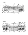
- the device shown in FIG. 3 is likewise arranged on the spindle box 1 or the sleeve flange of a machine tool and surrounds the spindle 2 provided with the clamping device 3.
- the ring line 5 with the approximately rectangular cross section 7 also opens into the annular gap 8, which forms an endless ring nozzle through which the fluid can flow out into a continuous fluid curtain.
- This fluid curtain can be of any size and can have a height of up to about 500 mm.
- the ring line 5 is open towards the processing point, the ring cover 29 being fastened to the spindle-side leg thereof by the screws 6 and by further screws 13, 13 '.
- the outside circumference Leg 39 of the ring line 5 and the free edge of the ring cover 29 form the annular gap 8.
- An installation element 35 is arranged in the channel 7. This represents a fluid-permeable installation in the channel 7, which is designed as a disk-shaped circular ring and divides the channel 7 into an upper, approximately rectangular partial channel 7 'and a lower, approximately wedge-shaped partial channel 7' '.
- the installation element 35 can be adapted to the respective embodiment of the device as required. It has a deflection ring 36 on the inlet side, which has the task of influencing the existing ring flow in such a way that the fluid exits at the annular gap 8 parallel to the spindle axis 27.
- the deflecting ring 36 can be an annular disk which is provided with a perforation or a vane grille.
- the installation element 35 can contain a filter ring 37 which retains material particles still present in the fluid. These settle above all in the upper part of the channel 7 'because of the centrifugal effect prevailing there on the outside channel wall and form a coating from which coarser particles can break out, which settle in the annular gap 8 and thus tear open the fluid curtain.
- the filter element 37 can consist of sieves, of which two or more layers with different mesh widths decreasing in the flow direction between 0.8 mm and 0.3 mm, preferably between 0.65 mm and 0.4 mm, are inserted.
- a rectification ring 38 can also be provided on the installation element 35, which additionally ensures the fluid flow parallel to the spindle axis 27. This is as a perforated washer or as Slotted grid formed. The installation element 35 is clamped on the spindle side by the ring cover 29 and thus held in its position.
- the device shown in FIG. 4 has two adjacent ring lines 17, 18, each of which has a channel 19, 20, which have an approximately rectangular cross section.
- a fluid flows out of the annular gaps 21, 22, two closed annular fluid curtains are also formed, which completely seal off the space within the two fluid streams from the environment.
- the openings 23, 24 are expediently located on opposite sides.
- such a line can also be provided with rectification internals (not shown).
- a few nozzles 26 are arranged on the side facing away from the headstock 1, which are directed obliquely against the spindle axis 27 and serve to cool the tool .
- the construction of the two ring lines 17, 18 corresponds to that in FIG. 2. They are composed of the ring 28 with the two channels 19, 20 and the two ring covers 29, 30 closing off the channels, with the ring cover 29, 30 and the adjacent outer peripheral channel wall Annular gaps 21, 22 are formed.
- the ring 28 is fastened by the screws 31 to the end face 32 of the headstock 1, while the ring cover 29 is fastened by the screws 13 and the ring cover 30 by a clamping ring 41.
- the same installation elements 35 are installed in the channels 19, 20 of the ring cover 17, 18 as in the channel 7 of the embodiment according to FIG. 3.
- the installation elements 35 provide upper, approximately rectangular partial channels 19 ', 20' and lower, approximately wedge-shaped subchannels 19 ′′, 20 ′′ are formed.
- the installation elements 35 in Fig. 4 have the same parts as in Fig. 3, i.e. a deflection ring 36, a filter element 37 and a rectification ring 38 and are held in position by the ring covers 29, 30.
- the installation element 35 ensures that the fluid flows out of the ring nozzle parallel to the spindle axis 27. At the same time, material particles in the fluid are retained in the installation element 35.
- any dust leakage can be avoided even more reliably, since material particles that cross the internal fluid process due to their large kinetic energy are then braked to such an extent that they are safely caught in the outer fluid curtain.
- the graphite dust captured by the fluid curtain is not transferred to the coolant system of the machine tool, but to a system set up separately, for example from the company Purolator.
- the backflowing medium loaded with material dust and material particles is continuously cleaned and then returned to the system by a pump. If a constant cleaning of the fluid is also achieved by such a system, it is not possible to completely remove all, in particular the smallest, material particles from the fluid.
- the faults mentioned in connection with the device according to FIG. 3 can be reliably avoided with the aid of the built-in elements 35.
- the annular gap 8 or 21, 22 can be made with a width of 0.25-0.4 mm in the devices according to FIGS. 1 to 4, wherein a known coolant liquid can be used as the fluid, which approximately Contains 97% water and about 3% of an additive that prevents rusting and can be under a pressure of two or more bar.
- Variants of the devices described consist in the fact that more than one feed line can be used, whereby the centrifugal effect in the upper subchannel is reduced and, if necessary, the deflection ring 36 can be dispensed with.
- one or more radial channels 40 are provided in the ring line in FIG. 3.
- branch lines 42 are also provided in the device according to FIG. 4, with which the space between two fluid curtains can be ventilated. Will these ventilation channels closed, when the fluid curtains are contracted, it can be concluded that the interior or the interiors of the fluid curtain or the fluid curtains have been completely closed. These vents can also be provided in FIGS. 1 and 2.
- the devices described can be used not only in milling machines with one or more spindles, but also in other machine tools, with other brittle dust-forming materials, e.g. ceramic materials can be processed while avoiding dust.
- the ring lines can either be arranged on the headstock or on the quill.
Landscapes
- Engineering & Computer Science (AREA)
- Mechanical Engineering (AREA)
- Auxiliary Devices For Machine Tools (AREA)
- Prevention Of Fouling (AREA)
Priority Applications (1)
| Application Number | Priority Date | Filing Date | Title |
|---|---|---|---|
| AT86109264T ATE51353T1 (de) | 1985-07-16 | 1986-07-07 | Vorrichtung zum unterdruecken der staubentwicklung und zum ableiten von spanmaterial an der bearbeitungsstation einer werkzeugmaschine. |
Applications Claiming Priority (4)
| Application Number | Priority Date | Filing Date | Title |
|---|---|---|---|
| CH3090/85 | 1985-07-16 | ||
| CH3090/85A CH668208A5 (de) | 1985-07-16 | 1985-07-16 | Verfahren und vorrichtung zum unterdruecken der staubentwicklung und zum ableiten von spanmaterial an der bearbeitungsstation einer werkzeugmaschine. |
| CH2458/86 | 1986-06-17 | ||
| CH2458/86A CH670414A5 (en) | 1986-06-17 | 1986-06-17 | Dust suppression and swarf removal for machine tool |
Publications (2)
| Publication Number | Publication Date |
|---|---|
| EP0212195A1 true EP0212195A1 (fr) | 1987-03-04 |
| EP0212195B1 EP0212195B1 (fr) | 1990-03-28 |
Family
ID=25690498
Family Applications (1)
| Application Number | Title | Priority Date | Filing Date |
|---|---|---|---|
| EP86109264A Expired - Lifetime EP0212195B1 (fr) | 1985-07-16 | 1986-07-07 | Dispositif pour diminuer la diffusion de la poussière et pour décharger des copeaux qui viennent d'un poste de travail d'une machine-outil |
Country Status (4)
| Country | Link |
|---|---|
| US (1) | US4798505A (fr) |
| EP (1) | EP0212195B1 (fr) |
| JP (1) | JPH0725007B2 (fr) |
| DE (1) | DE3669836D1 (fr) |
Cited By (3)
| Publication number | Priority date | Publication date | Assignee | Title |
|---|---|---|---|---|
| WO1997007332A1 (fr) * | 1995-08-17 | 1997-02-27 | Robert Bosch Gmbh | Plaque d'injecteur, notamment pour soupapes d'injection de carburant, et procede pour sa fabrication |
| CN102580866A (zh) * | 2012-03-29 | 2012-07-18 | 李燕 | 一种高压喷嘴及具有该高压喷嘴的用水清洗油污的喷头 |
| CN103100931A (zh) * | 2011-11-14 | 2013-05-15 | 深圳市速锋科技有限公司 | 一种滚珠高速主轴的防尘罩 |
Families Citing this family (18)
| Publication number | Priority date | Publication date | Assignee | Title |
|---|---|---|---|---|
| JPS6456940U (fr) * | 1987-10-05 | 1989-04-10 | ||
| JPH04176538A (ja) * | 1990-11-07 | 1992-06-24 | Hamai Sangyo Kk | 工作機械のツールホルダ |
| US5245152A (en) * | 1992-06-09 | 1993-09-14 | Klein Tools, Inc. | Dielectric fluid dust extraction system for electric discharge machine |
| DE4309719C2 (de) * | 1993-03-25 | 1997-10-09 | Leonhardt Bollmann | Vorrichtung zum Entfernen bzw. Beseitigen von Stäuben beim Herstellen von Elektroden |
| EP1350596B1 (fr) * | 1996-02-15 | 2005-04-27 | Zeta Heiwa Ltd. | Dispositif de séparation d'impuretés d'un liquide de refroidissement dans une machine-outil |
| US5993121A (en) * | 1997-05-20 | 1999-11-30 | The Boeing Company | Cooling device for multi-axis rotary machining tool |
| CN1104305C (zh) * | 1998-12-28 | 2003-04-02 | 株式会社泽塔平和 | 机床内的冷却液喷嘴 |
| JP3626947B2 (ja) * | 2002-08-14 | 2005-03-09 | ファナック株式会社 | 工作機械の切粉及び切削液飛散防止装置 |
| US7582004B2 (en) * | 2003-07-11 | 2009-09-01 | United Technologies Corporation | Coolant nozzle |
| CN102848259A (zh) * | 2012-09-18 | 2013-01-02 | 江苏松野数控科技有限公司 | 一种易生灰粉类零件切削加工防护用水帘系统 |
| DE202013100065U1 (de) | 2013-01-08 | 2014-04-09 | Wolfcraft Gmbh | Hilfsvorrichtung zur Verwendung beim Kreisbogenfräsen |
| US9555480B2 (en) * | 2013-08-19 | 2017-01-31 | The Boeing Company | Fluid-fed vacuum cutters |
| CN108637789A (zh) * | 2018-07-17 | 2018-10-12 | 苏州美瑞时科技有限公司 | 一种用于汽车零部件加工表面钻孔装置 |
| JP6737847B2 (ja) * | 2018-07-31 | 2020-08-12 | ファナック株式会社 | 主軸装置 |
| JP6810113B2 (ja) * | 2018-09-07 | 2021-01-06 | ファナック株式会社 | 工作機械 |
| CN113059371A (zh) * | 2021-03-04 | 2021-07-02 | 黄亚辉 | 一种机械加工用数控机床 |
| CN115122144B (zh) * | 2022-08-25 | 2024-07-16 | 李常清 | 一种用于五金件加工的精密数控机床 |
| WO2025007160A2 (fr) * | 2023-06-30 | 2025-01-02 | Physical Systems, Inc. | Systèmes et procédés d'installation d'éléments de fixation liés |
Citations (9)
| Publication number | Priority date | Publication date | Assignee | Title |
|---|---|---|---|---|
| DE254235C (fr) * | 1900-01-01 | |||
| CH208032A (de) * | 1939-01-07 | 1939-12-31 | Kuttner Julius | Spritzschutzvorrichtung an Werkzeugmaschinen. |
| CH241054A (de) * | 1944-04-22 | 1946-02-15 | Landert Heinr | Schleifmaschine mit Flüssigkeitskühlung. |
| US2574865A (en) * | 1947-06-17 | 1951-11-13 | Edwards Miles Lowell | Spray nozzle |
| GB696198A (en) * | 1952-04-21 | 1953-08-26 | Bourdon Tools Ltd | A new or improved method of and means for applying liquid coolants and lubricants tothe cutting tools of machine tools and to the work pieces being operated upon by such cutting tools |
| FR1305478A (fr) * | 1961-07-28 | 1962-10-05 | Bertin & Cie | Perfectionnements aux trompes et tubulures ou conduits à voile divergent fluide |
| DE1646196A1 (de) * | 1964-08-13 | 1969-08-21 | Wallis Neil Rudolf | Vorrichtung fuer das Aufspruehen von UEberzuegen auf Gegenstaende |
| LU59759A1 (fr) * | 1968-11-07 | 1970-01-13 | ||
| WO1983001747A1 (fr) * | 1981-11-18 | 1983-05-26 | Hans Moss | Ajutage de soufflage pour un ecoulement de sortie silencieux de gaz |
Family Cites Families (7)
| Publication number | Priority date | Publication date | Assignee | Title |
|---|---|---|---|---|
| US1611028A (en) * | 1924-11-21 | 1926-12-14 | Thomas W Harrison | Drill spray |
| US2327483A (en) * | 1940-06-13 | 1943-08-24 | Linde Air Prod Co | Apparatus for rock piercing and similar operations |
| US2404149A (en) * | 1941-08-20 | 1946-07-16 | Merco Trinkle Machine Co | Contouring machine |
| US2644275A (en) * | 1949-04-11 | 1953-07-07 | E C T A Soc | Water curtain projecting device for use with sand blasting apparatus |
| US2837972A (en) * | 1955-02-17 | 1958-06-10 | Gulf Research Development Co | Accessory for metal cutting machines |
| US3245321A (en) * | 1963-06-14 | 1966-04-12 | Onsrud Machine Works Inc | Profiling machine |
| JPS5310194A (en) * | 1976-07-15 | 1978-01-30 | Tadahiko Kuno | Sand blasting method and sand blasting instrument |
-
1986
- 1986-07-07 EP EP86109264A patent/EP0212195B1/fr not_active Expired - Lifetime
- 1986-07-07 DE DE8686109264T patent/DE3669836D1/de not_active Expired - Lifetime
- 1986-07-15 US US06/885,950 patent/US4798505A/en not_active Expired - Fee Related
- 1986-07-16 JP JP16773086A patent/JPH0725007B2/ja not_active Expired - Lifetime
Patent Citations (9)
| Publication number | Priority date | Publication date | Assignee | Title |
|---|---|---|---|---|
| DE254235C (fr) * | 1900-01-01 | |||
| CH208032A (de) * | 1939-01-07 | 1939-12-31 | Kuttner Julius | Spritzschutzvorrichtung an Werkzeugmaschinen. |
| CH241054A (de) * | 1944-04-22 | 1946-02-15 | Landert Heinr | Schleifmaschine mit Flüssigkeitskühlung. |
| US2574865A (en) * | 1947-06-17 | 1951-11-13 | Edwards Miles Lowell | Spray nozzle |
| GB696198A (en) * | 1952-04-21 | 1953-08-26 | Bourdon Tools Ltd | A new or improved method of and means for applying liquid coolants and lubricants tothe cutting tools of machine tools and to the work pieces being operated upon by such cutting tools |
| FR1305478A (fr) * | 1961-07-28 | 1962-10-05 | Bertin & Cie | Perfectionnements aux trompes et tubulures ou conduits à voile divergent fluide |
| DE1646196A1 (de) * | 1964-08-13 | 1969-08-21 | Wallis Neil Rudolf | Vorrichtung fuer das Aufspruehen von UEberzuegen auf Gegenstaende |
| LU59759A1 (fr) * | 1968-11-07 | 1970-01-13 | ||
| WO1983001747A1 (fr) * | 1981-11-18 | 1983-05-26 | Hans Moss | Ajutage de soufflage pour un ecoulement de sortie silencieux de gaz |
Cited By (4)
| Publication number | Priority date | Publication date | Assignee | Title |
|---|---|---|---|---|
| WO1997007332A1 (fr) * | 1995-08-17 | 1997-02-27 | Robert Bosch Gmbh | Plaque d'injecteur, notamment pour soupapes d'injection de carburant, et procede pour sa fabrication |
| US6434826B1 (en) | 1995-08-17 | 2002-08-20 | Robert Bosch Gmbh | Method for producing a nozzle plate |
| CN103100931A (zh) * | 2011-11-14 | 2013-05-15 | 深圳市速锋科技有限公司 | 一种滚珠高速主轴的防尘罩 |
| CN102580866A (zh) * | 2012-03-29 | 2012-07-18 | 李燕 | 一种高压喷嘴及具有该高压喷嘴的用水清洗油污的喷头 |
Also Published As
| Publication number | Publication date |
|---|---|
| JPH0725007B2 (ja) | 1995-03-22 |
| JPS6274546A (ja) | 1987-04-06 |
| DE3669836D1 (de) | 1990-05-03 |
| US4798505A (en) | 1989-01-17 |
| EP0212195B1 (fr) | 1990-03-28 |
Similar Documents
| Publication | Publication Date | Title |
|---|---|---|
| EP0212195B1 (fr) | Dispositif pour diminuer la diffusion de la poussière et pour décharger des copeaux qui viennent d'un poste de travail d'une machine-outil | |
| DE4442662B4 (de) | Kühl und Absaugvorrichtung für eine Werkzeugmaschine | |
| EP0827806A1 (fr) | Cylindre de serrage pour serrer un boulon de serrage, boulon de serrage associé et système de serrage pour l'utilisation avec copeaux tombant | |
| DE3800050A1 (de) | Absaugverfahren fuer pulverfoermigen bearbeitungsabfall | |
| DE3429842A1 (de) | Werkzeughaltevorrichtung | |
| DE69109668T2 (de) | Methode und gerät zum filtern einer teilchenflüssigkeitssuspension. | |
| EP4201588A1 (fr) | Outil de fraisage pour une fraiseuse dentaire et agencement composé d'une broche de fraisage et d'un outil de fraisage | |
| DE60305585T2 (de) | Schleifverfahren und Schleifmaschine | |
| DE60020929T2 (de) | Hilfsfilter und Verfahren zur Entfernung von Partikeln aus einer filtrierten Schneidflüssigkeit | |
| DE102004018727A1 (de) | Schleifteller mit Eigenabsaugeinrichtung und Verfahren zum Entfernen von Schleifpatikeln | |
| EP0522098B1 (fr) | Dispositif pour l'aspiration de residus d'usinage | |
| DE3525092A1 (de) | Insbesondere transportables trenngeraet wie handkreissaege, trennschleifgeraet od.dgl. | |
| DE3931141C2 (fr) | ||
| DE60310248T2 (de) | Verteiler für rotierendes filter und rotierendes filter mit einem solchen verteiler | |
| DE3217146C2 (fr) | ||
| DE69424708T2 (de) | Filter für Flüssigkeiten mit festen suspendierten Partikeln, insbesondere für Schmier- und Kühlflüssigkeit in Maschinenwerkzeugen | |
| DE19861132B4 (de) | Werkzeugmaschine mit Abdeckung | |
| CH668208A5 (de) | Verfahren und vorrichtung zum unterdruecken der staubentwicklung und zum ableiten von spanmaterial an der bearbeitungsstation einer werkzeugmaschine. | |
| DE4125358A1 (de) | Vorrichtung zum ausfiltern von feststoff-partikeln aus fluessigkeiten | |
| CH670414A5 (en) | Dust suppression and swarf removal for machine tool | |
| DE102014013129A1 (de) | Werkzeugmaschine zur spanabhebenden Bearbeitung eines Werkstücks mittels einer Minimalmengenschmierung sowie Verfahren zur Reinigung einer derartigen Werkzeugmaschine | |
| EP0758573B1 (fr) | Outil de meulage diamanté pour l'usinage de surface de pierre naturelle ou artificielle | |
| DE19626174C1 (de) | Fräsmaschine mit einer Abführeinrichtung für Schlämme, Stäube und Späne | |
| DE3317409A1 (de) | Vorrichtung zum absaugen von spaenen | |
| DE2405583C2 (de) | Drehbarer Schneidkopf für eine Gewinnungsmaschine im untertägigen Bergbau |
Legal Events
| Date | Code | Title | Description |
|---|---|---|---|
| PUAI | Public reference made under article 153(3) epc to a published international application that has entered the european phase |
Free format text: ORIGINAL CODE: 0009012 |
|
| AK | Designated contracting states |
Kind code of ref document: A1 Designated state(s): AT BE CH DE FR GB IT LI LU NL SE |
|
| 17P | Request for examination filed |
Effective date: 19870326 |
|
| 17Q | First examination report despatched |
Effective date: 19880406 |
|
| GRAA | (expected) grant |
Free format text: ORIGINAL CODE: 0009210 |
|
| AK | Designated contracting states |
Kind code of ref document: B1 Designated state(s): AT BE CH DE FR GB IT LI LU NL SE |
|
| REF | Corresponds to: |
Ref document number: 51353 Country of ref document: AT Date of ref document: 19900415 Kind code of ref document: T |
|
| ITF | It: translation for a ep patent filed | ||
| REF | Corresponds to: |
Ref document number: 3669836 Country of ref document: DE Date of ref document: 19900503 |
|
| GBT | Gb: translation of ep patent filed (gb section 77(6)(a)/1977) | ||
| ET | Fr: translation filed | ||
| PG25 | Lapsed in a contracting state [announced via postgrant information from national office to epo] |
Ref country code: LU Free format text: LAPSE BECAUSE OF NON-PAYMENT OF DUE FEES Effective date: 19900731 Ref country code: BE Effective date: 19900731 |
|
| PLBE | No opposition filed within time limit |
Free format text: ORIGINAL CODE: 0009261 |
|
| STAA | Information on the status of an ep patent application or granted ep patent |
Free format text: STATUS: NO OPPOSITION FILED WITHIN TIME LIMIT |
|
| BERE | Be: lapsed |
Owner name: STARRFRASMASCHINEN A.G. Effective date: 19900731 |
|
| 26N | No opposition filed | ||
| ITTA | It: last paid annual fee | ||
| PGFP | Annual fee paid to national office [announced via postgrant information from national office to epo] |
Ref country code: NL Payment date: 19920731 Year of fee payment: 7 |
|
| PG25 | Lapsed in a contracting state [announced via postgrant information from national office to epo] |
Ref country code: NL Effective date: 19940201 |
|
| NLV4 | Nl: lapsed or anulled due to non-payment of the annual fee | ||
| PGFP | Annual fee paid to national office [announced via postgrant information from national office to epo] |
Ref country code: AT Payment date: 19940714 Year of fee payment: 9 |
|
| PGFP | Annual fee paid to national office [announced via postgrant information from national office to epo] |
Ref country code: SE Payment date: 19940731 Year of fee payment: 9 |
|
| EAL | Se: european patent in force in sweden |
Ref document number: 86109264.1 |
|
| PG25 | Lapsed in a contracting state [announced via postgrant information from national office to epo] |
Ref country code: AT Effective date: 19950707 |
|
| PG25 | Lapsed in a contracting state [announced via postgrant information from national office to epo] |
Ref country code: SE Effective date: 19950708 |
|
| EUG | Se: european patent has lapsed |
Ref document number: 86109264.1 |
|
| PGFP | Annual fee paid to national office [announced via postgrant information from national office to epo] |
Ref country code: DE Payment date: 19960722 Year of fee payment: 11 |
|
| PGFP | Annual fee paid to national office [announced via postgrant information from national office to epo] |
Ref country code: FR Payment date: 19960724 Year of fee payment: 11 |
|
| PGFP | Annual fee paid to national office [announced via postgrant information from national office to epo] |
Ref country code: GB Payment date: 19960729 Year of fee payment: 11 |
|
| PGFP | Annual fee paid to national office [announced via postgrant information from national office to epo] |
Ref country code: CH Payment date: 19961023 Year of fee payment: 11 |
|
| PG25 | Lapsed in a contracting state [announced via postgrant information from national office to epo] |
Ref country code: GB Free format text: LAPSE BECAUSE OF NON-PAYMENT OF DUE FEES Effective date: 19970707 |
|
| PG25 | Lapsed in a contracting state [announced via postgrant information from national office to epo] |
Ref country code: LI Free format text: LAPSE BECAUSE OF NON-PAYMENT OF DUE FEES Effective date: 19970731 Ref country code: CH Free format text: LAPSE BECAUSE OF NON-PAYMENT OF DUE FEES Effective date: 19970731 |
|
| GBPC | Gb: european patent ceased through non-payment of renewal fee |
Effective date: 19970707 |
|
| REG | Reference to a national code |
Ref country code: CH Ref legal event code: PL |
|
| PG25 | Lapsed in a contracting state [announced via postgrant information from national office to epo] |
Ref country code: FR Free format text: LAPSE BECAUSE OF NON-PAYMENT OF DUE FEES Effective date: 19980331 |
|
| PG25 | Lapsed in a contracting state [announced via postgrant information from national office to epo] |
Ref country code: DE Free format text: LAPSE BECAUSE OF NON-PAYMENT OF DUE FEES Effective date: 19980401 |
|
| REG | Reference to a national code |
Ref country code: FR Ref legal event code: ST |
|
| PG25 | Lapsed in a contracting state [announced via postgrant information from national office to epo] |
Ref country code: IT Free format text: LAPSE BECAUSE OF NON-PAYMENT OF DUE FEES;WARNING: LAPSES OF ITALIAN PATENTS WITH EFFECTIVE DATE BEFORE 2007 MAY HAVE OCCURRED AT ANY TIME BEFORE 2007. THE CORRECT EFFECTIVE DATE MAY BE DIFFERENT FROM THE ONE RECORDED. Effective date: 20050707 |