EP0212416A1 - Fokussierungskollimator und Verfahren zu seiner Herstellung - Google Patents
Fokussierungskollimator und Verfahren zu seiner Herstellung Download PDFInfo
- Publication number
- EP0212416A1 EP0212416A1 EP86110754A EP86110754A EP0212416A1 EP 0212416 A1 EP0212416 A1 EP 0212416A1 EP 86110754 A EP86110754 A EP 86110754A EP 86110754 A EP86110754 A EP 86110754A EP 0212416 A1 EP0212416 A1 EP 0212416A1
- Authority
- EP
- European Patent Office
- Prior art keywords
- strips
- collimator
- strip
- finished
- stacking
- Prior art date
- Legal status (The legal status is an assumption and is not a legal conclusion. Google has not performed a legal analysis and makes no representation as to the accuracy of the status listed.)
- Granted
Links
Images

Classifications
-
- G—PHYSICS
- G21—NUCLEAR PHYSICS; NUCLEAR ENGINEERING
- G21K—HANDLING OF PARTICLES OR IONISING RADIATION NOT OTHERWISE PROVIDED FOR; IRRADIATION DEVICES; GAMMA RAY OR X-RAY MICROSCOPES
- G21K1/00—Arrangements for handling particles or ionising radiation, e.g. focusing or moderating
- G21K1/02—Arrangements for handling particles or ionising radiation, e.g. focusing or moderating using diaphragms, collimators
- G21K1/025—Arrangements for handling particles or ionising radiation, e.g. focusing or moderating using diaphragms, collimators using multiple collimators, e.g. Bucky screens; other devices for eliminating undesired or dispersed radiation
-
- G—PHYSICS
- G01—MEASURING; TESTING
- G01T—MEASUREMENT OF NUCLEAR OR X-RADIATION
- G01T1/00—Measuring X-radiation, gamma radiation, corpuscular radiation, or cosmic radiation
- G01T1/16—Measuring radiation intensity
- G01T1/161—Applications in the field of nuclear medicine, e.g. in vivo counting
- G01T1/164—Scintigraphy
- G01T1/1641—Static instruments for imaging the distribution of radioactivity in one or two dimensions using one or several scintillating elements; Radio-isotope cameras
- G01T1/1642—Static instruments for imaging the distribution of radioactivity in one or two dimensions using one or several scintillating elements; Radio-isotope cameras using a scintillation crystal and position sensing photodetector arrays, e.g. ANGER cameras
Definitions
- the invention relates to collimators, and more particularly relates to focusing collimators which are built up by stacking up corrugated strips, one adjacent the next.
- collimator is a conventional cone beam collimator which is built up from a plurality of identical strips. Each strip is corrugated to create a plurality of channels which all aim at a single focal point. The strips are tapered in cross-section and in the ideal case all the focal points of the individual strips would coincide at a single focal point.
- a conventional collimator has channels of constant size in the stacking plane. This has the consequence that sensitivity drops off rapidly from the center of the collimator to the edge.
- Another object is to provide such a collimator which is comparatively easy to manufacture, particularly using automated and automatable assembly techniques.
- Still a further object is to provide such a collimator which has a reasonably constant sensitivity over its entire surface.
- Yet another object is, in general, to improve on known focusing collimators, and particularly known collimators which converge or diverge in one or two or orthagonal directions, e.g. cone beam collimators.
- a focusing collimator which comprises a plurality of corrugated strips which are of different shapes in cross-section.
- the strips are stacked up in a stacking plane, and the cross-sections of the strips are defined by the intersections of each of the strips with the stacking plane.
- each strip is shaped in cross-section as a part of a different radial sector of a common predetermined annulus. Because this annulus is common to all the strips which make up the collimator, a punctate or substantially punctate focal point within the stacking plane of interest is inherently built into the device.
- each strip can be individually sized (as by automatic equipment) and then stacked on a flat surface.
- a plurality of strips can all be stacked (as by manual assembly) on a mandrel having a curvature equalling the inner radius of curvature of the annulus and then machined flat, as by milling.
- Each of the strips may subtend a constant solid angle.
- the channels in the collimator also subtend a constant solid angle. This has the consequence that the channels of the collimator increase in size from center to edge. This results in a more uniform sensitivity across the entire surface of the collimator, instead of a steady reduction in sensitivity from center to edge that results from using channels of constant diameter.
- cone beam collimator The preferred embodiment described below is a cone beam collimator.
- the invention is not limited to cone beam collimators; it is equally applicable to any collimator which is built up of a stack of corrugated strips which focus in the stacking plane, and where it is desired to minimize or eliminate stacking error.
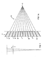
- a strip generally indicated by reference numeral 2 is shown on end and from the side, respectively.
- the strip 2 has a plurality of channels 4.
- the channels 4 are all aimed at a common focal point 6 to form a two-dimensional fan beam generally indicated by reference numeral 8.
- the channels 4 are separated from each other by corrugations 10.
- the corrugations 10 may be formed in a variety of ways, but the details of corrugations 10 are not part of the invention.
- strip as used herein may denote a unitary element made for example of a single sheet of corrugated material, the term also encompasses a two-element structure such as a corrugated member backed with a flat sheet.
- strip includes all structures which either by themselves or in cooperation with neighboring ones form channels which collimate, e.g., gamma radiation.
- the finished collimator is intended for use with a gamma ray scintillation camera so that the strips 2 are made of lead, but this not a part of the invention.
- the material used for the strips 2 depends upon the type of radiation to be collimated.
- FIG. 2 A disadvantage of known cone beam collimators for gamma radiation is illustrated in Fig. 2.
- a conventional finished collimator a plurality of finished strips 2A - 2H are stacked adjacent each other in a stacking plane.
- Fig. 2 is exaggerated for clarity and is not to scale; there would always be more than 8 strips in a collimator and their misalignment would never be so pronounced.
- Each of the finished strips 2A - 2H in the collimator is identical to all the others, and each has an individual focal point 6A - 6H.
- the focal points 6A - 6H do not coincide in the stacking plane; they are spaced from each other.
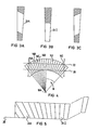
- individual semi-finished strips 14A - 14K in accordance with a preferred embodiment of the invention are all identically shaped and are all different radial sectors of a common predetermined annulus generally indicated by reference numeral annulus 16.
- each of the strips 14A - 14K is corrugated in the same way as is the strip 2 in Fig. lA.
- a single focal point, namely the center 16A of the annulus 16, is therefore built into the assembly.
- these individual semi-finished strips 14A - 14K can be used to manufacture a cone beam collimator in one of two preferred ways.
- the first preferred method is illustrated in Fig. 4.
- the semi-finished strips 14A etc. are all stacked, as by hand, on a mandrel 18.
- the mandrel 18 has a cylindrical cross-section and has the same radius of curvature (and the same center 16A) as the inner radius of curvature of the annulus 16.
- the semi-finished strips 14A etc. are bonded together (as by adhesive) so that they form a unitary structure. This is then milled or otherwise machined along the two parallel planes 20 and 22 to form a flat plate.
- Fig. 5 Another alternative is illustrated in Fig. 5.
- the semi-finished strips 14A, etc. are shaped, as by automatic machinery, in accordance with their intended positions before they are stacked and bonded together.
- finished strip 24A is formed by cutting down one of the semi-finished strips 14 in the manner shown in Fig. 3A
- strip 241 is formed by cutting down one of the semi-finished strips 14 in the manner shown in Fig. 3B, and so forth.
- Each individual strip to be included in the collimator is appropriately dimensioned, and stacked up on a flat plane 26. All the finished strips 24A etc. are bonded together (as by adhesive) to form the finished collimator.
- a single strip from a known cone beam collimator may differ but slightly, or even imperceptibly, from a single strip from a finished collimator in accordance with the invention.
- Fig. 1 can equally well be said to illustrate a known collimator strip and a strip for making a collimator in accordance with the invention.
- two strips from a collimator in accordance with the invention may appear identical. This is because the geometrical relationships in accordance with the invention do not reside in the dimensions of any one particular strip, but rather in the overall relationship between the dimensions of all of the strips in the collimator, taken as a class.
- there is a relationship between the cross-sectional shape of each strip and the position of that strip in the finished collimator While this relationship may not be observable from a comparison of neighboring strips because of manufacturing tolerances, it is nonetheless true of all the strips, taken as a class.
- each of the illustrated finished strips is a radial sector, each is wider at its radially outward end than at its radially inward end. This means that, as shown in Fig. lA, the channels in each finished strip are wider at one end than at the other. This relationship is preserved in the illustrated preferred embodiment, so that at the edges of the finished collimator, the channel openings are wider than they are at the center. In this preferred embodiment, each channel subtends a constant solid angle, (i.e. is conical) so that sensitivity remains constant over the entire surface of the collimator rather than dropping off from center to edge.
- each of the semi-finished strips 14A etc. subtend the same solid angle. As long as all of them are radial sectors of a common predetermined annulus, they can subtend different angles and yet retain the punctate focus of the preferred embodiment discussed above.
- the strip 14A can have half the angular width of strip 148. This can be selected when, for example, it is desired to have cylindrical chamels in each strip rather than conical ones.
Landscapes
- Physics & Mathematics (AREA)
- Health & Medical Sciences (AREA)
- Spectroscopy & Molecular Physics (AREA)
- Engineering & Computer Science (AREA)
- High Energy & Nuclear Physics (AREA)
- Medical Informatics (AREA)
- Biomedical Technology (AREA)
- General Health & Medical Sciences (AREA)
- General Engineering & Computer Science (AREA)
- Nuclear Medicine, Radiotherapy & Molecular Imaging (AREA)
- Optics & Photonics (AREA)
- Life Sciences & Earth Sciences (AREA)
- General Physics & Mathematics (AREA)
- Molecular Biology (AREA)
- Nuclear Medicine (AREA)
- Analysing Materials By The Use Of Radiation (AREA)
Applications Claiming Priority (2)
| Application Number | Priority Date | Filing Date | Title |
|---|---|---|---|
| US765611 | 1985-08-14 | ||
| US06/765,611 US4958081A (en) | 1985-08-14 | 1985-08-14 | Focusing collimator and method for making it |
Publications (2)
| Publication Number | Publication Date |
|---|---|
| EP0212416A1 true EP0212416A1 (de) | 1987-03-04 |
| EP0212416B1 EP0212416B1 (de) | 1989-11-08 |
Family
ID=25074004
Family Applications (1)
| Application Number | Title | Priority Date | Filing Date |
|---|---|---|---|
| EP86110754A Expired EP0212416B1 (de) | 1985-08-14 | 1986-08-04 | Fokussierungskollimator und Verfahren zu seiner Herstellung |
Country Status (4)
| Country | Link |
|---|---|
| US (1) | US4958081A (de) |
| EP (1) | EP0212416B1 (de) |
| JP (1) | JPS6265000A (de) |
| DE (1) | DE3666892D1 (de) |
Cited By (4)
| Publication number | Priority date | Publication date | Assignee | Title |
|---|---|---|---|---|
| EP0289737A1 (de) * | 1987-03-20 | 1988-11-09 | Siemens Aktiengesellschaft | Szintillationskamera mit Punkt-Fokus-Kollimator und Verfahren zu deren Verwendung |
| FR2673728A1 (fr) * | 1991-03-08 | 1992-09-11 | Assistance Publique | Systeme de gamma camera a haute sensibilite. |
| EP0506023A1 (de) * | 1991-03-27 | 1992-09-30 | Kabushiki Kaisha Toshiba | Hochpräzisionskollimator mit einzelner Fokallinie und Verfahren zur Herstellung eines solchen Kollimators. |
| EP0506029A1 (de) * | 1991-03-27 | 1992-09-30 | Kabushiki Kaisha Toshiba | Präzis fokussierter Kollimator und Verfahren zur Herstellung eines präzis fokussierten Kollimators |
Families Citing this family (9)
| Publication number | Priority date | Publication date | Assignee | Title |
|---|---|---|---|---|
| US5068882A (en) * | 1990-08-27 | 1991-11-26 | General Electric Company | Dual parallel cone beam circular scanning trajectories for reduced data incompleteness in three-dimensional computerized tomography |
| JPH04300196A (ja) * | 1991-03-27 | 1992-10-23 | Toshiba Corp | カッタユニット組立方法 |
| US5231654A (en) * | 1991-12-06 | 1993-07-27 | General Electric Company | Radiation imager collimator |
| US5550678A (en) * | 1994-03-14 | 1996-08-27 | Siemens Medical Systems, Inc. | Focussing collimator of the Platz-Heinzelmann type and method of making Platz-Heinzelmann type collimators |
| JPH0998970A (ja) * | 1995-10-06 | 1997-04-15 | Canon Inc | X線撮像装置 |
| RU2242748C1 (ru) * | 2003-08-19 | 2004-12-20 | Общество с ограниченной ответственностью "Институт рентгеновской оптики" | Детектирующий узел для рентгеновских дифракционных измерений |
| US8315428B2 (en) * | 2009-10-22 | 2012-11-20 | Siemens Medical Solutions Usa, Inc. | Automatic line identification and pairing for nuclear imaging collimator vector map characterization |
| US8483460B2 (en) | 2011-01-10 | 2013-07-09 | Siemens Medical Solutions Usa, Inc. | System and method for measuring hole orientation for SPECT collimators |
| US8340386B2 (en) | 2011-01-10 | 2012-12-25 | Siemens Medical Solutions Usa, Inc. | System and method for measuring hole orientation for SPECT collimators |
Citations (3)
| Publication number | Priority date | Publication date | Assignee | Title |
|---|---|---|---|---|
| US3937969A (en) * | 1973-05-07 | 1976-02-10 | G. D. Searle & Co. | Gamma ray camera system with corrugated collimators |
| US4081687A (en) * | 1975-08-27 | 1978-03-28 | Precise Corporation | Collimator for gamma ray cameras |
| WO1982000897A1 (en) * | 1980-09-10 | 1982-03-18 | A Larsson | Multitube collimator for instance scintillation cameras |
Family Cites Families (3)
| Publication number | Priority date | Publication date | Assignee | Title |
|---|---|---|---|---|
| US2638554A (en) * | 1949-10-05 | 1953-05-12 | Bartow Beacons Inc | Directivity control of x-rays |
| US2731718A (en) * | 1954-06-04 | 1956-01-24 | Harry E Goss | Inside pipe cutter |
| US3407300A (en) * | 1966-04-14 | 1968-10-22 | Picker Corp | Collimator and method of making same |
-
1985
- 1985-08-14 US US06/765,611 patent/US4958081A/en not_active Expired - Fee Related
-
1986
- 1986-08-04 EP EP86110754A patent/EP0212416B1/de not_active Expired
- 1986-08-04 DE DE8686110754T patent/DE3666892D1/de not_active Expired
- 1986-08-11 JP JP61187040A patent/JPS6265000A/ja active Pending
Patent Citations (3)
| Publication number | Priority date | Publication date | Assignee | Title |
|---|---|---|---|---|
| US3937969A (en) * | 1973-05-07 | 1976-02-10 | G. D. Searle & Co. | Gamma ray camera system with corrugated collimators |
| US4081687A (en) * | 1975-08-27 | 1978-03-28 | Precise Corporation | Collimator for gamma ray cameras |
| WO1982000897A1 (en) * | 1980-09-10 | 1982-03-18 | A Larsson | Multitube collimator for instance scintillation cameras |
Cited By (8)
| Publication number | Priority date | Publication date | Assignee | Title |
|---|---|---|---|---|
| EP0289737A1 (de) * | 1987-03-20 | 1988-11-09 | Siemens Aktiengesellschaft | Szintillationskamera mit Punkt-Fokus-Kollimator und Verfahren zu deren Verwendung |
| FR2673728A1 (fr) * | 1991-03-08 | 1992-09-11 | Assistance Publique | Systeme de gamma camera a haute sensibilite. |
| WO1992015896A1 (fr) * | 1991-03-08 | 1992-09-17 | Assistance Publique | Systeme de gamma-camera a haute sensibilite |
| US5448073A (en) * | 1991-03-08 | 1995-09-05 | Jeanguillaume; Christian R. | High sensitivity gamma camera system |
| EP0506023A1 (de) * | 1991-03-27 | 1992-09-30 | Kabushiki Kaisha Toshiba | Hochpräzisionskollimator mit einzelner Fokallinie und Verfahren zur Herstellung eines solchen Kollimators. |
| EP0506029A1 (de) * | 1991-03-27 | 1992-09-30 | Kabushiki Kaisha Toshiba | Präzis fokussierter Kollimator und Verfahren zur Herstellung eines präzis fokussierten Kollimators |
| US5198680A (en) * | 1991-03-27 | 1993-03-30 | Kabushiki Kaisha Toshiba | High precision single focus collimator and method for manufacturing high precision single focus collimator |
| US5303459A (en) * | 1991-03-27 | 1994-04-19 | Kabushiki Kaisha Toshiba | Method for manufacturing precisely focused collimator |
Also Published As
| Publication number | Publication date |
|---|---|
| US4958081A (en) | 1990-09-18 |
| DE3666892D1 (en) | 1989-12-14 |
| JPS6265000A (ja) | 1987-03-24 |
| EP0212416B1 (de) | 1989-11-08 |
Similar Documents
| Publication | Publication Date | Title |
|---|---|---|
| US4958081A (en) | Focusing collimator and method for making it | |
| US5099134A (en) | Collimator and a method of producing a collimator for a scintillator | |
| EP1634303B1 (de) | Röntgenlicht-kollimator mit antistreu-wirkung für ct scanner | |
| EP0051932A1 (de) | Im Fokus zentrierender Strahlungskonzentrator | |
| US4251747A (en) | One piece astigmatic grid for color picture tube electron gun | |
| CA2389871C (en) | Rotatable cylinder dual beam modulator | |
| US20070064878A1 (en) | Antiscatter grid having a cell-like structure of radiation channels, and method for producing such an antiscatter grid | |
| JPH0583881B2 (de) | ||
| DE10046314B4 (de) | Herstellungsverfahren für einen Strahlendetektor | |
| US20050135562A1 (en) | Collimator for a computer tomograph | |
| EP1367603B1 (de) | Röntgenstrahlungskollimator und Herstellungsverfahren | |
| US4081687A (en) | Collimator for gamma ray cameras | |
| US3939451A (en) | Balance control for use in 4-channel stereophonic system | |
| US20050111627A1 (en) | Method of shielding scattered radiation in front of a detector array | |
| DE102018219673A1 (de) | Laserlichtquelleneinheit | |
| US7415098B2 (en) | Collimator for stray radiation, in particular for medical x-ray devices and method for producing said collimator | |
| EP1927999B1 (de) | Herstellungsverfahren für ein Röntgen-CT-System | |
| US8761346B2 (en) | Multilayer total internal reflection optic devices and methods of making and using the same | |
| US20160155525A1 (en) | X-Ray Filter For X-Ray Powder Diffraction | |
| JPS6017380A (ja) | 断層コリメ−タ及びその製造方法 | |
| US12580092B2 (en) | Collimator and methods of forming same | |
| WO1989012898A1 (en) | Slit radiography device provided with absorption elements, and procedure for producing absorption elements | |
| WO2000021096A9 (en) | Beam hardening filter for x-ray source | |
| JPH066682Y2 (ja) | フレ−ムレス構造の固定子鉄心 | |
| Hoover et al. | Multiplate focusing collimator |
Legal Events
| Date | Code | Title | Description |
|---|---|---|---|
| PUAI | Public reference made under article 153(3) epc to a published international application that has entered the european phase |
Free format text: ORIGINAL CODE: 0009012 |
|
| AK | Designated contracting states |
Kind code of ref document: A1 Designated state(s): DE FR GB NL |
|
| 17P | Request for examination filed |
Effective date: 19870326 |
|
| 17Q | First examination report despatched |
Effective date: 19880716 |
|
| GRAA | (expected) grant |
Free format text: ORIGINAL CODE: 0009210 |
|
| AK | Designated contracting states |
Kind code of ref document: B1 Designated state(s): DE FR GB NL |
|
| REF | Corresponds to: |
Ref document number: 3666892 Country of ref document: DE Date of ref document: 19891214 |
|
| ET | Fr: translation filed | ||
| PLBE | No opposition filed within time limit |
Free format text: ORIGINAL CODE: 0009261 |
|
| STAA | Information on the status of an ep patent application or granted ep patent |
Free format text: STATUS: NO OPPOSITION FILED WITHIN TIME LIMIT |
|
| 26N | No opposition filed | ||
| PGFP | Annual fee paid to national office [announced via postgrant information from national office to epo] |
Ref country code: NL Payment date: 19920831 Year of fee payment: 7 |
|
| PGFP | Annual fee paid to national office [announced via postgrant information from national office to epo] |
Ref country code: DE Payment date: 19921023 Year of fee payment: 7 |
|
| PGFP | Annual fee paid to national office [announced via postgrant information from national office to epo] |
Ref country code: GB Payment date: 19930714 Year of fee payment: 8 |
|
| PG25 | Lapsed in a contracting state [announced via postgrant information from national office to epo] |
Ref country code: NL Effective date: 19940301 |
|
| NLV4 | Nl: lapsed or anulled due to non-payment of the annual fee | ||
| PG25 | Lapsed in a contracting state [announced via postgrant information from national office to epo] |
Ref country code: DE Effective date: 19940503 |
|
| PG25 | Lapsed in a contracting state [announced via postgrant information from national office to epo] |
Ref country code: GB Effective date: 19940804 |
|
| GBPC | Gb: european patent ceased through non-payment of renewal fee |
Effective date: 19940804 |
|
| PGFP | Annual fee paid to national office [announced via postgrant information from national office to epo] |
Ref country code: FR Payment date: 19950823 Year of fee payment: 10 |
|
| PG25 | Lapsed in a contracting state [announced via postgrant information from national office to epo] |
Ref country code: FR Effective date: 19970430 |
|
| REG | Reference to a national code |
Ref country code: FR Ref legal event code: ST |