EP0213284A2 - Montage dans la traverse du corps de couplage d'un attelage de remorque - Google Patents
Montage dans la traverse du corps de couplage d'un attelage de remorque Download PDFInfo
- Publication number
- EP0213284A2 EP0213284A2 EP86107434A EP86107434A EP0213284A2 EP 0213284 A2 EP0213284 A2 EP 0213284A2 EP 86107434 A EP86107434 A EP 86107434A EP 86107434 A EP86107434 A EP 86107434A EP 0213284 A2 EP0213284 A2 EP 0213284A2
- Authority
- EP
- European Patent Office
- Prior art keywords
- cross
- pull rod
- bearing tube
- section
- ring
- Prior art date
- Legal status (The legal status is an assumption and is not a legal conclusion. Google has not performed a legal analysis and makes no representation as to the accuracy of the status listed.)
- Granted
Links
- 230000008878 coupling Effects 0.000 title claims abstract description 27
- 238000010168 coupling process Methods 0.000 title claims abstract description 27
- 238000005859 coupling reaction Methods 0.000 title claims abstract description 27
- 230000005540 biological transmission Effects 0.000 claims abstract description 9
- 230000015572 biosynthetic process Effects 0.000 claims description 13
- 239000000314 lubricant Substances 0.000 claims description 3
- 230000001050 lubricating effect Effects 0.000 claims description 2
- 230000002093 peripheral effect Effects 0.000 claims description 2
- 230000007423 decrease Effects 0.000 description 2
- 239000000853 adhesive Substances 0.000 description 1
- 230000001070 adhesive effect Effects 0.000 description 1
- 238000005452 bending Methods 0.000 description 1
- 230000033228 biological regulation Effects 0.000 description 1
- 238000006073 displacement reaction Methods 0.000 description 1
- 239000004519 grease Substances 0.000 description 1
- 238000009434 installation Methods 0.000 description 1
- 238000000034 method Methods 0.000 description 1
- 210000002445 nipple Anatomy 0.000 description 1
- 230000035939 shock Effects 0.000 description 1
Images
Classifications
-
- B—PERFORMING OPERATIONS; TRANSPORTING
- B60—VEHICLES IN GENERAL
- B60D—VEHICLE CONNECTIONS
- B60D1/00—Traction couplings; Hitches; Draw-gear; Towing devices
- B60D1/48—Traction couplings; Hitches; Draw-gear; Towing devices characterised by the mounting
- B60D1/50—Traction couplings; Hitches; Draw-gear; Towing devices characterised by the mounting resiliently mounted
Definitions
- the invention relates to a mounting of the coupling body of a trailer hitch on a towing vehicle by means of a pull rod extending from the coupling body, this pull rod passing through a crossbeam bore of a crossbar attached to the towing vehicle, wherein the pulling rod is further guided in a passage of a bearing tube fastened to the crossbar, concentric with the crossbar bore is, and wherein the pull rod on the bearing tube in both directions of force, ie is supported for traction and shear force transmission.
- tie rod mounting is known from DE-AS 27 32 610.
- the bearing tube passes through the truss bore.
- the inner cross section of the passage of the bearing tube is therefore smaller than the cross section of the crossbeam bore. This means that the cross-section of the tie rod at the point of passage through the crossbeam and for assembly reasons must be smaller than the cross-section of the crossbeam over its entire length between the point of passage and its free end.
- the cross-section of the crossbeam is, on the other hand, standardized, so that for the cross-section of the tie rod a dimension that cannot be exceeded due to the finite ring cross-section of the bearing tube at the point of passage through the crossbeam results, which is smaller than the cross-sectional dimension of the crossbeam. This dimension available for the cross-section of the drawbar has always been considered sufficient.
- the invention has for its object to design a storage of the generic type so that increased lateral forces, i.e. Forces transverse to the axis of the coupling body lying in the direction of travel can be introduced into the coupling body.
- the cross-section of the tie rod essentially occupies the full cross-section of the cross-member bore, and that the bearing tube on the side of the cross-member remote from the coupling body extends exclusively in the direction away from the coupling body.
- the bearing tube no longer takes up part of the cross-section bore cross section, so that the cross-section of the tie rod can be increased to the full extent of the cross-section cross section bore. It is of course not necessary that the cross-section of the tie rod corresponds exactly to the full dimension of the cross-section of the cross-hole. It is sufficient if the cross-sectional enlargement option is used is made, which is given by the omission of the bearing tube cross-section in the area of the truss bore.
- the guide of the pull rod in the bearing tube is at least as good in the solution according to the invention as in the known solution.
- the installation conditions are also not deteriorated in the solution according to the invention. On the contrary: You can now move the coupling body even closer to the crossbar and, as a rule, there is sufficient space on the back of the crossbar for the bearing tube that starts from the crossbar and extends exclusively in the direction away from the coupling body.
- tie rod-side tension abutment which can be attached to the tie rod after passage of the tie rod through the passage of the bearing tube, and that the tie rod is supported in the pushing direction on a cover or yoke part, which according to the attachment of the pull abutment on the pull rod is applied to the end of the bearing tube remote from the crossbar.
- an annular tensile force buffer can be arranged between the tensile rod-side abutment and the shoulder formation, which can also be under prestress, as will be explained in more detail below.
- a system of tension limit stops can be provided between the tension rod-side tension abutment and the shoulder formation, for example in such a way that the tension force buffer axially between an axially normal and radially outward-pointing flange of an L-cross-section ring and a first, radially outer shoulder surface of the shoulder formation is accommodated and that the tension limit stops are formed by a second radially inner shoulder surface of the shoulder formation and the end facing the traverse of an axially parallel, the traction force buffer on its radially inner side adjacent part of the L cross-section ring.
- the tensile force buffer can also be enclosed between the surfaces of the L cross-sectional ring and the shoulder formation in such a way that it is fully corseted from a predetermined tensile force and therefore itself acts as a stroke limit stop thanks to its volume incompressibility.
- the pull abutment is formed by a segment ring with at least two segments, which is received and secured in a segment ring receiving groove of the pull rod.
- This embodiment deserves preference over other possible embodiments of the train abutment, for example by means of screws, because the course of forces can be clearly controlled and because there is no risk that the most heavily loaded surfaces will be disturbed by the load for disassembly and any subsequent reassembly.
- the segment ring can be secured in any way.
- a segment encircling ring is preferably provided which surrounds the segment ring; the segment mounting ring on the segment ring can be secured in the axial direction on the one hand by the axially normal flange of the L cross-section ring and on the other hand by a radially resilient spring ring, the latter being spring-loaded into a spring ring receiving groove in the outer peripheral surface of the segment ring.
- a thrust force buffer can also be provided in the pushing direction. With regard to a pretension to be discussed later, it is advisable to arrange this thrust force buffer between the end of the pull rod remote from the crossbar and the cover or yoke part.
- thrust travel limit stops can be provided between the pull rod and the bearing tube, which of course can also be attached to parts permanently connected to the pull rod or the bearing tube, for example the cover or yoke part.
- the lid or yoke part can be with the end remote from the traverse of the bearing tube can be screwed, whereby the prestress can simultaneously be introduced into the buffer, ie the tensile force buffer and the thrust force buffer, by the screw connection.
- the cover or yoke part can be screwed, in contrast to the known solution according to DE-As 27 32 610, several screws can be used in parallel, so that the tightening torques on the individual screws required for applying the pretension can be considerably smaller than in the case of the known solution, which facilitates assembly and disassembly.
- the push rod can be guided in the passage of the bearing tube by means of a sliding sleeve, in particular made of plastic, as is known per se from DE-AS 27 32 610.
- the bearing tube can be provided with at least one lubricating nipple in order to be able to lubricate and relubricate the sliding guide between the tie rod and the passage of the bearing tube.
- the bearing tube can be fastened to the crossbar by flanging, as is known from DE-AS 27 32 610.
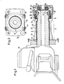
- the coupling body is designated 10.
- the coupling body 10 has a tubular pull rod 12.
- the pull rod 12 passes through a traverse 14 which is attached to the towing vehicle in a conventional manner.
- the cross member 14 is designed for the passage of the tie rod 12 with a cross member bore 16 of a standard size.
- the outer cross section of the tie rod 12 at the point of passage through the crossmember 14 and in the subsequent one Longitudinal section A corresponds approximately to the cross section of the crossbeam bore 16.
- a bearing tube 18 is flanged to the crossbeam 14 by means of a flange 20 which can be seen in FIG. 2.
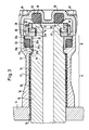
- This bearing tube 18 has a passage 22 which receives the pull rod 12 by means of a sliding sleeve 24.
- a shoulder formation 26 is provided, which is formed by a radially outer first shoulder surface 26a and a radially inner second shoulder surface 26b.
- An annular tensile force buffer 28 bears on the first shoulder surface 26a, the other end of which bears against a radially outwardly directed flange 30a of an L cross-sectional ring 30.
- the axially directed sleeve part 30b rests on the radially inner side of the tensile force buffer 28 and has its end 30c opposite the second shoulder surface 26b.
- the L-shaped cross-section ring 30 rests with its radially outwardly directed flange 30a on a pull abutment of the pull rod 12 in the form of a segment ring 32.
- the segment ring 32 consists of at least two 180 ° segments, which in turn have an L cross section and are inserted with their radially inwardly directed legs 32a into a segment ring receiving groove 34 near the free end of the pull rod 12.
- the segments of the segment ring 32 are secured against radial exit movement from the segment ring receiving groove 34 by a segment encircling ring 36.
- the segment encircling ring 36 is secured in the axial direction by the radially outward flange 30a of the L cross-sectional ring on the one hand and by a spring ring 38 on the other hand, which is spring-loaded into a spring ring receiving groove 40 on the outside of the segment ring 32.
- the segment ring 32 is secured against rotation relative to the tie rod 12 by grooved pins 42 or the like, which are each inserted half in a half bore on the radially inward leg 32a of the segment ring 32 and a half bore in the tie rod, this half bore in the end surface near the end the segment ring receiving groove 34 opens out.
- the bearing tube 18 is closed by a cover part 44 which is screwed to the bearing tube by fastening screws 46.
- An annular thrust force buffer 50 is accommodated in an annular chamber 48 of the cover part 44 and, on the other hand, bears against the axially normal end face 52 of the pull rod 12.
- Lubricant recesses 55 are provided in the sliding sleeve 24 and can be supplied with oil or grease from a lubricant (not shown).
- the assembly procedure is as follows:
- the bearing tube 18 with the sliding sleeve 24 inserted is flanged to the cross member 14.
- the pull rod 12 is then pushed through the crossbeam bore 16 and the passage 22 of the bearing tube 18 until the conical surface 54 of the pull rod 12 comes into contact with the conical surface 56 of the bearing tube 18.
- the L cross-sectional ring 30 and the tensile force buffer 28 are then brought into the position shown in FIG. 3.
- the 180 ° segments of the segment ring 32 are then inserted into the segment ring receiving groove 34, secured against rotation by the grooved pins 42 and against radial displacement by the segment encircling ring 36.
- the segment encircling ring 36 is secured by inserting the spring ring 38.
- the cover part 44 is inserted with the inserted thrust force buffer 50 on the bearing tube 18 and screwed to the latter by means of the screws 46.
- the tensile force buffer 28 and the thrust force buffer 50 are pressurized, whereby the conical surface 54 rises again from the conical surface 56, but the radially inner shoulder surface 26b maintains a distance from the end 30c of the sleeve part 30b.
- tractive force is exerted by the pull rod via the segment ring 32, the L cross section ring 30, the tensile force buffer 28 and the radially outer shoulder surface 26 a to the bearing tube 18 and from the bearing tube 18 to the cross member 14.
- the tensile force buffer 28 is deformed to such an extent that the end 30c of the axially directed sleeve 30b abuts against the radially inner shoulder surface 26b.
- a pushing force such as occurs when the trailer runs against the braked towing vehicle, is exerted by the pull rod 12 via the pushing force buffer 50 onto the cover part 44, from the cover part 44 onto the screws 46, from the screws 46 onto the bearing tube 18 and from that Transfer the bearing tube 18 to the cross member 14.
- the thrust exceeds a predetermined dimension, the conical surfaces 54 and 56 come to a stop;
Landscapes
- Engineering & Computer Science (AREA)
- Transportation (AREA)
- Mechanical Engineering (AREA)
- Mutual Connection Of Rods And Tubes (AREA)
- Mounting Of Bearings Or Others (AREA)
- Motor Power Transmission Devices (AREA)
- Fluid-Damping Devices (AREA)
- Jib Cranes (AREA)
- Fittings On The Vehicle Exterior For Carrying Loads, And Devices For Holding Or Mounting Articles (AREA)
Priority Applications (1)
| Application Number | Priority Date | Filing Date | Title |
|---|---|---|---|
| AT86107434T ATE51590T1 (de) | 1985-08-27 | 1986-06-02 | Lagerung des kupplungskoerpers einer anhaengerkupplung in der traverse. |
Applications Claiming Priority (2)
| Application Number | Priority Date | Filing Date | Title |
|---|---|---|---|
| DE3530565A DE3530565C2 (de) | 1985-08-27 | 1985-08-27 | Längskraftabstützung des Kupplungskörpers einer Anhängerkupplung |
| DE3530565 | 1985-08-27 |
Publications (3)
| Publication Number | Publication Date |
|---|---|
| EP0213284A2 true EP0213284A2 (fr) | 1987-03-11 |
| EP0213284A3 EP0213284A3 (en) | 1988-10-19 |
| EP0213284B1 EP0213284B1 (fr) | 1990-04-04 |
Family
ID=6279459
Family Applications (1)
| Application Number | Title | Priority Date | Filing Date |
|---|---|---|---|
| EP86107434A Expired - Lifetime EP0213284B1 (fr) | 1985-08-27 | 1986-06-02 | Montage dans la traverse du corps de couplage d'un attelage de remorque |
Country Status (5)
| Country | Link |
|---|---|
| US (1) | US4715611A (fr) |
| EP (1) | EP0213284B1 (fr) |
| AT (1) | ATE51590T1 (fr) |
| CA (1) | CA1278591C (fr) |
| DE (2) | DE3530565C2 (fr) |
Families Citing this family (4)
| Publication number | Priority date | Publication date | Assignee | Title |
|---|---|---|---|---|
| DE3842037A1 (de) * | 1988-12-14 | 1990-06-28 | Wabco Westinghouse Fahrzeug | Einrichtung zur erfassung einer axialkraft einer deichselkupplung |
| DE3935479A1 (de) * | 1989-10-25 | 1991-05-02 | Pfister Gmbh | Anhaengerkupplung |
| DE4240559A1 (de) * | 1992-12-02 | 1994-06-09 | Rockinger Spezial Fab Joh | Anordnung einer Anhängerkupplung an einem Fahrzeug |
| DE102004045254B4 (de) * | 2004-09-17 | 2009-12-24 | Jost-Werke Gmbh & Co. Kg | Anhängerkupplung mit Zugstangenbefestigung |
Citations (1)
| Publication number | Priority date | Publication date | Assignee | Title |
|---|---|---|---|---|
| DE2732610A1 (de) | 1977-07-19 | 1979-02-01 | Rockinger Spezial Fab Joh | Lagerung fuer die zugstange einer anhaengerkupplung |
Family Cites Families (10)
| Publication number | Priority date | Publication date | Assignee | Title |
|---|---|---|---|---|
| US1991684A (en) * | 1932-06-13 | 1935-02-19 | Holland Hitch Co | Cushion tow hook |
| CH195194A (de) * | 1935-10-10 | 1938-01-15 | Ringfeder Gmbh | Kreuzgelenk-Anhängerkupplung für Geländefahrzeuge. |
| US2591487A (en) * | 1947-10-24 | 1952-04-01 | Wirz Ernst | Draw hook with lock cap for trailers |
| DE1708881U (de) * | 1953-12-10 | 1955-10-13 | Rockinger Spezial Fab Joh | Anhaengerkupplung. |
| DE1004939B (de) * | 1956-11-03 | 1957-03-21 | Hans Franke Spedition G M B H | Zugstangensicherung fuer Anhaengerkupplungen |
| DE1555378B2 (de) * | 1966-11-04 | 1976-10-14 | Ing. Paul Friese, Maschinenbau, 7931 Allmendingen | Anhaengerkupplung |
| CH471498A (de) * | 1967-09-02 | 1969-04-15 | Kober Herbert | Schaltungsanordnung an einem Transformator zu dessen Strombegrenzung |
| DE2206617A1 (de) * | 1972-02-11 | 1973-08-23 | Rockinger Spezial Fab Joh | Anhaengerkupplung |
| DE2912277A1 (de) * | 1979-03-28 | 1980-10-09 | Rockinger Spezial Fab Joh | Anhaengerkupplung |
| DE3009914A1 (de) * | 1980-03-14 | 1981-09-24 | Emil Doll KG, Fahrzeug- u. Karosseriebau, 7603 Oppenau | Kupplungsvorrichtung fuer einachs- und tandem-anhaenger |
-
1985
- 1985-08-27 DE DE3530565A patent/DE3530565C2/de not_active Expired - Lifetime
-
1986
- 1986-06-02 AT AT86107434T patent/ATE51590T1/de not_active IP Right Cessation
- 1986-06-02 EP EP86107434A patent/EP0213284B1/fr not_active Expired - Lifetime
- 1986-06-02 DE DE8686107434T patent/DE3670049D1/de not_active Expired - Lifetime
- 1986-07-21 CA CA000514257A patent/CA1278591C/fr not_active Expired - Lifetime
- 1986-08-14 US US06/896,889 patent/US4715611A/en not_active Expired - Fee Related
Patent Citations (1)
| Publication number | Priority date | Publication date | Assignee | Title |
|---|---|---|---|---|
| DE2732610A1 (de) | 1977-07-19 | 1979-02-01 | Rockinger Spezial Fab Joh | Lagerung fuer die zugstange einer anhaengerkupplung |
Also Published As
| Publication number | Publication date |
|---|---|
| US4715611A (en) | 1987-12-29 |
| DE3530565C2 (de) | 2002-03-07 |
| DE3670049D1 (de) | 1990-05-10 |
| EP0213284B1 (fr) | 1990-04-04 |
| EP0213284A3 (en) | 1988-10-19 |
| DE3530565A1 (de) | 1987-03-12 |
| ATE51590T1 (de) | 1990-04-15 |
| CA1278591C (fr) | 1991-01-02 |
Similar Documents
| Publication | Publication Date | Title |
|---|---|---|
| DE3915991C2 (fr) | ||
| EP0730107A2 (fr) | Frein à disque | |
| DE2148860A1 (de) | Reibungs-Zugkupplung,insbesondere fuer Eisenbahnwagen | |
| EP3442847A1 (fr) | Dispositif de traction et de poussée | |
| EP3155274A1 (fr) | Dispositif de fixation à haute résistance | |
| DE102012221232A1 (de) | Lageranordnung, insbesondere für Spannlager | |
| DE3403297C2 (fr) | ||
| EP1247715A1 (fr) | Dispositif de tamponnement et de traction pour véhicules ferroviaires | |
| EP0213284B1 (fr) | Montage dans la traverse du corps de couplage d'un attelage de remorque | |
| EP1085228B1 (fr) | Dispositif de débrayage pour actionneur d'embrayage hydraulique | |
| DE2161580B2 (de) | Vorrichtung zum Verstellen und Feststellen der Höhe von Zuggabeln an Anhängern | |
| EP4606674A1 (fr) | Dispositif avec un dispositif de traction et de poussée d'un système d'attelage pour un véhicule ferroviaire | |
| DE102012013964B4 (de) | Vorrichtung zum Andrücken einer Zahnstange an ein Ritzel | |
| DE69514215T2 (de) | Spielfreie Zugstangenanordnung für einen Güterwagon | |
| EP0000325B1 (fr) | Palier de fixation pour barre d'attelage | |
| EP3825202B1 (fr) | Barre de traction, en particulier pour un accouplement de pare-chocs central d'un véhicule ferroviaire, et écrou destinée au raccordement d'un tirant ancrage d'une barre de traction à un tube de traction de la barre de traction | |
| DE2117962A1 (de) | Kupplung | |
| EP1069020B1 (fr) | Dispositif de traction pour véhicules ferroviaires | |
| DE19650577A1 (de) | Betätigungsvorrichtung für eine Kraftfahrzeugkupplung | |
| EP0785108B1 (fr) | Dispositif de verrouillage pour l'assemblage de façon démontable de deux éléments | |
| DE3035922A1 (de) | Zug- und stossvorrichtung fuer eine mittelpufferkupplung eines schienenfahrzeuges | |
| DE102023115092A1 (de) | Scheibenbremse für ein Fahrzeug, sowie Fahrzeug mit einer Scheibenbremse | |
| DE10010610A1 (de) | Schienenfahrzeug mit Wagenkasten und mindestens einem Fahrwerk | |
| DE3334250C2 (fr) | ||
| EP1186507A1 (fr) | Dispositif de traction |
Legal Events
| Date | Code | Title | Description |
|---|---|---|---|
| PUAI | Public reference made under article 153(3) epc to a published international application that has entered the european phase |
Free format text: ORIGINAL CODE: 0009012 |
|
| AK | Designated contracting states |
Kind code of ref document: A2 Designated state(s): AT CH DE FR IT LI NL SE |
|
| PUAL | Search report despatched |
Free format text: ORIGINAL CODE: 0009013 |
|
| AK | Designated contracting states |
Kind code of ref document: A3 Designated state(s): AT CH DE FR IT LI NL SE |
|
| 17P | Request for examination filed |
Effective date: 19881201 |
|
| 17Q | First examination report despatched |
Effective date: 19890531 |
|
| GRAA | (expected) grant |
Free format text: ORIGINAL CODE: 0009210 |
|
| AK | Designated contracting states |
Kind code of ref document: B1 Designated state(s): AT CH DE FR IT LI NL SE |
|
| REF | Corresponds to: |
Ref document number: 51590 Country of ref document: AT Date of ref document: 19900415 Kind code of ref document: T |
|
| ITF | It: translation for a ep patent filed | ||
| REF | Corresponds to: |
Ref document number: 3670049 Country of ref document: DE Date of ref document: 19900510 |
|
| ET | Fr: translation filed | ||
| PLBI | Opposition filed |
Free format text: ORIGINAL CODE: 0009260 |
|
| 26 | Opposition filed |
Opponent name: RINGFEDER GMBH Effective date: 19901221 |
|
| NLR1 | Nl: opposition has been filed with the epo |
Opponent name: RINGFEDER GMBH |
|
| PLBN | Opposition rejected |
Free format text: ORIGINAL CODE: 0009273 |
|
| STAA | Information on the status of an ep patent application or granted ep patent |
Free format text: STATUS: OPPOSITION REJECTED |
|
| 27O | Opposition rejected |
Effective date: 19920213 |
|
| NLR2 | Nl: decision of opposition | ||
| ITTA | It: last paid annual fee | ||
| EAL | Se: european patent in force in sweden |
Ref document number: 86107434.2 |
|
| PGFP | Annual fee paid to national office [announced via postgrant information from national office to epo] |
Ref country code: NL Payment date: 20040530 Year of fee payment: 19 |
|
| PGFP | Annual fee paid to national office [announced via postgrant information from national office to epo] |
Ref country code: CH Payment date: 20040602 Year of fee payment: 19 |
|
| PGFP | Annual fee paid to national office [announced via postgrant information from national office to epo] |
Ref country code: SE Payment date: 20040603 Year of fee payment: 19 Ref country code: AT Payment date: 20040603 Year of fee payment: 19 |
|
| PGFP | Annual fee paid to national office [announced via postgrant information from national office to epo] |
Ref country code: DE Payment date: 20040604 Year of fee payment: 19 |
|
| PGFP | Annual fee paid to national office [announced via postgrant information from national office to epo] |
Ref country code: FR Payment date: 20040609 Year of fee payment: 19 |
|
| PG25 | Lapsed in a contracting state [announced via postgrant information from national office to epo] |
Ref country code: IT Free format text: LAPSE BECAUSE OF NON-PAYMENT OF DUE FEES;WARNING: LAPSES OF ITALIAN PATENTS WITH EFFECTIVE DATE BEFORE 2007 MAY HAVE OCCURRED AT ANY TIME BEFORE 2007. THE CORRECT EFFECTIVE DATE MAY BE DIFFERENT FROM THE ONE RECORDED. Effective date: 20050602 Ref country code: AT Free format text: LAPSE BECAUSE OF NON-PAYMENT OF DUE FEES Effective date: 20050602 |
|
| PG25 | Lapsed in a contracting state [announced via postgrant information from national office to epo] |
Ref country code: SE Free format text: LAPSE BECAUSE OF NON-PAYMENT OF DUE FEES Effective date: 20050603 |
|
| PG25 | Lapsed in a contracting state [announced via postgrant information from national office to epo] |
Ref country code: LI Free format text: LAPSE BECAUSE OF NON-PAYMENT OF DUE FEES Effective date: 20050630 Ref country code: CH Free format text: LAPSE BECAUSE OF NON-PAYMENT OF DUE FEES Effective date: 20050630 |
|
| PG25 | Lapsed in a contracting state [announced via postgrant information from national office to epo] |
Ref country code: NL Free format text: LAPSE BECAUSE OF NON-PAYMENT OF DUE FEES Effective date: 20060101 |
|
| PG25 | Lapsed in a contracting state [announced via postgrant information from national office to epo] |
Ref country code: DE Free format text: LAPSE BECAUSE OF NON-PAYMENT OF DUE FEES Effective date: 20060103 |
|
| REG | Reference to a national code |
Ref country code: CH Ref legal event code: PL |
|
| EUG | Se: european patent has lapsed | ||
| PG25 | Lapsed in a contracting state [announced via postgrant information from national office to epo] |
Ref country code: FR Free format text: LAPSE BECAUSE OF NON-PAYMENT OF DUE FEES Effective date: 20060228 |
|
| NLV4 | Nl: lapsed or anulled due to non-payment of the annual fee |
Effective date: 20060101 |
|
| REG | Reference to a national code |
Ref country code: FR Ref legal event code: ST Effective date: 20060228 |