EP0214643A2 - Joint de rainure et languette endtre deux panneaux de bois voisins - Google Patents
Joint de rainure et languette endtre deux panneaux de bois voisins Download PDFInfo
- Publication number
- EP0214643A2 EP0214643A2 EP86112408A EP86112408A EP0214643A2 EP 0214643 A2 EP0214643 A2 EP 0214643A2 EP 86112408 A EP86112408 A EP 86112408A EP 86112408 A EP86112408 A EP 86112408A EP 0214643 A2 EP0214643 A2 EP 0214643A2
- Authority
- EP
- European Patent Office
- Prior art keywords
- groove
- tongue
- panels
- panel
- rear surface
- Prior art date
- Legal status (The legal status is an assumption and is not a legal conclusion. Google has not performed a legal analysis and makes no representation as to the accuracy of the status listed.)
- Granted
Links
Images
Classifications
-
- E—FIXED CONSTRUCTIONS
- E04—BUILDING
- E04F—FINISHING WORK ON BUILDINGS, e.g. STAIRS, FLOORS
- E04F13/00—Coverings or linings, e.g. for walls or ceilings
- E04F13/07—Coverings or linings, e.g. for walls or ceilings composed of covering or lining elements; Sub-structures therefor; Fastening means therefor
- E04F13/08—Coverings or linings, e.g. for walls or ceilings composed of covering or lining elements; Sub-structures therefor; Fastening means therefor composed of a plurality of similar covering or lining elements
- E04F13/0801—Separate fastening elements
- E04F13/0832—Separate fastening elements without load-supporting elongated furring elements between wall and covering elements
- E04F13/0833—Separate fastening elements without load-supporting elongated furring elements between wall and covering elements not adjustable
- E04F13/0846—Separate fastening elements without load-supporting elongated furring elements between wall and covering elements not adjustable the fastening elements engaging holes or grooves in the side faces of the covering elements
-
- E—FIXED CONSTRUCTIONS
- E04—BUILDING
- E04F—FINISHING WORK ON BUILDINGS, e.g. STAIRS, FLOORS
- E04F13/00—Coverings or linings, e.g. for walls or ceilings
- E04F13/07—Coverings or linings, e.g. for walls or ceilings composed of covering or lining elements; Sub-structures therefor; Fastening means therefor
- E04F13/08—Coverings or linings, e.g. for walls or ceilings composed of covering or lining elements; Sub-structures therefor; Fastening means therefor composed of a plurality of similar covering or lining elements
- E04F13/10—Coverings or linings, e.g. for walls or ceilings composed of covering or lining elements; Sub-structures therefor; Fastening means therefor composed of a plurality of similar covering or lining elements of wood or with an outer layer of wood
Definitions
- the invention relates to a Tongue and groove connection between two adjacent wooden panels for cladding walls, ceilings or the like, the panels each having a front surface and a rear surface.
- Known tongue and groove connections of wood panels are usually such that a groove of constant width, measured in the direction of the thickness of the panel, is incorporated at the edge of one panel and that a tongue of constant thickness, measured in the direction of the thickness of the other panel, is incorporated Panels, protrudes.
- the width of the groove and the thickness of the tongue correspond to one another, so that when the tongue and groove are pushed together to connect the two panels, they are mutually fixed in both opposite directions perpendicular to the rear surface of the panels. It was found that with this type of tongue-and-groove connection, inserting the tongue into the groove sometimes makes it difficult and that the tight tongue-and-groove fit allows the panels to work freely on the connection, especially when the wood shrinks while drying out. with special needs. In addition, the attachment of the panels to the grooved edge on a substructure supporting the panels is relatively cumbersome.
- the invention has for its object to make a tongue and groove connection between two adjacent wood cladding panels available, which leads to a significant ease of assembly of the panels and to an improved relative movement behavior of the attached panels.
- the tongue and groove connection is designed according to the invention as in the characterizing part of claim 1 specified.
- the groove is sufficiently large compared to the tongue, it is even possible to insert it at an initial angle of the panel to be assembled relative to the corresponding neighboring panel, which is followed by tipping into the mounting position.
- the tongue slides easily into the corresponding groove. All of this also applies to panels that - as is more common in practice - are no longer completely level due to warping.
- the above projection helps as a lower guide surface when inserting the tongue into the groove. Furthermore, movements of the panels relative to one another, for example due to temperature fluctuations, or the working of the panels, in particular due to changes in moisture, are facilitated. Finally, the tongue and / or the groove cheek on the rear side become more stable, since they close in the critical transition area the rest of the panel is thicker.
- the panels consist of a wood material, in particular solid wood, which can be brushed on the visible or front surface of the panel. They are generally rectangular, often elongated, cladding panels.
- the area of the tongue that comes into the area of the groove opening of the neighboring panel when the panels are installed is referred to as the tongue root.
- This spring root usually represents the rear end of the spring at the transition to the rest of the panel of normal thickness, but it can also be a bit away from the transition described, for example if the spring height is greater than the groove depth.
- the width of the groove is essentially continuously greater than the thickness of the tongue at the corresponding point means that the groove has a greater width over its entire depth from the mouth of the groove to the groove base than the thickness of the tongue at the corresponding point has, which results in the game described practically over the entire groove depth or spring height.
- the contact surfaces formed by the tongue and groove surfaces parallel to the rear surface retain their position with respect to the rear panel surfaces or the substructure even in the event of relative displacements of adjacent panels. Due to the rear surface-side contact of the panels on the substructure, the tongue is at least essentially in contact with a groove wall on one side, so that despite the play mentioned, the relative position of adjacent panels is defined correctly perpendicular to their rear surface.
- the invention also relates to the wooden panels themselves, which are designed in such a way that they enable the tongue-and-groove connections described above to be created with corresponding neighboring panels, cf. Claim 4.
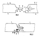
- the panel 2 on the right in FIG. 1 has a groove 4 in its left edge which runs perpendicular to the plane of the drawing along the edge of the panel 2.
- the upper wall or boundary surface 6 of the groove 4 in FIG. 1 is parallel to the rear surface 8 and to the front surface 10 of the panel.
- the groove base, which is semicircular in section, is denoted by 12 and the groove opening pointing to the left is denoted by 14.
- the lower wall or boundary surface 16 of the groove 4 in FIG. 1 is inclined at an angle in the range from 8 to 15 ° to the rear surface 8 such that the width w of the groove 4, measured perpendicular to the rear surface 8, extends from the groove mouth 14 continuously reduced in the direction of the groove base 12.
- the edge of the panel 2 projects further to the left than above the groove 4, that is to say on the front surface side of the groove 4. As a result, a protrusion 18 is formed. Above the groove 4, the edge of the panel 2 runs at right angles to the rear surface 8 and the front surface 10 for a piece of the panel height. Then there is an initially concave and then convex curvature for a visually appealing, smooth transition into the front surface 10.
- the panel 2 on the left in FIG. 1 has a spring 20 on its right edge in FIG. 1, the upper surface or boundary surface 22 of which is also parallel to the rear 8 and front 10 of this panel 2.
- the lower surface or boundary surface 24 extends essentially at the same angle as the lower boundary surface 16 of the groove 4 relative to the rear surface 8 of the associated panel 2.
- the height of the spring 22, measured horizontally in FIG. 1, from the spring root 26 to the free one Spring end 28 is substantially equal to the depth of groove 4 measured horizontally in FIG. 1 from groove base 12 to groove opening 14. Thickness d of spring 20, measured vertically in FIG.
- the left panel 2 can be inserted with its spring 20 into the groove 4 of the right panel 2, with play remaining between the lower boundary surfaces 16 and 22 when pushed together.
- this insertion is extremely easy due to the play, supported by the semi-circular rounding of the free spring end 28 and the overhang 18 serving as a support surface. initially even inserting the tongue 20 into the groove 4 obliquely from above. If necessary, you can also slightly round off or chamfer the right edge of the left panel 2 at the transition to the rear surface.
- FIG. 2 shows the pushed-together state of the two panels 2.
- a fastening claw 26 can be seen, which in the section of FIG. 2 has the shape of a lying U that is open to the right with a lower, horizontal extension leg to the left Has.
- the U of the claw 26 engages around the overhang 18 from above, left and below.
- the left panel 2 rests on the lower leg of the claw 26, which is elongated to the left.
- the claw 26 is pushed onto the overhang 18 from the left and nailed to the supporting substructure with a nail 28 through the left extension leg before attachment of the left panel 2 .
- the upper, almost horizontal leg of the claw 26 takes place in the space between the spring 20 and the lower boundary surface 16 of the groove 4.
- the protrusion 18 described has the further advantage that viewing openings through the butt joints between adjacent panels 2 are prevented everywhere in the lining created with the panels 2, even where this protrusion 18 is milled away at the corner of the panel because of the transition into an edge provided with spring 20 is because either a spring 20 or a projection 18 cover the butt joints between adjacent panels 2 everywhere, even when the wood of the panels 2 shrinks and the butt joints become larger as a result.
- Such situations occur with panels which are each formed with a groove on two adjoining edges and with a tongue on the other two adjoining edges.
- the tongues and the grooves in the panel according to the invention can be succinctly described as wedge-shaped, possibly rounded at the end.
- the illustrated exemplary embodiments can be modified such that, in the case of a wedge-shaped tongue 4, the groove 20 has the surface 16 parallel to the surface 6 at a distance from the groove opening 14, or that, in the case of a wedge-shaped groove 20, the tongue 4 has the surface 24 parallel to the surface 22.
Landscapes
- Engineering & Computer Science (AREA)
- Architecture (AREA)
- Civil Engineering (AREA)
- Structural Engineering (AREA)
- Life Sciences & Earth Sciences (AREA)
- Wood Science & Technology (AREA)
- Finishing Walls (AREA)
Priority Applications (1)
| Application Number | Priority Date | Filing Date | Title |
|---|---|---|---|
| AT86112408T ATE62308T1 (de) | 1985-09-09 | 1986-09-08 | Nut-feder-verbindung zwischen zwei benachbarten holzpaneelen. |
Applications Claiming Priority (4)
| Application Number | Priority Date | Filing Date | Title |
|---|---|---|---|
| DE3532112 | 1985-09-09 | ||
| DE19853532112 DE3532112A1 (de) | 1985-09-09 | 1985-09-09 | Verkleidungspaneel |
| DE19853541039 DE3541039A1 (de) | 1985-11-19 | 1985-11-19 | Verkleidungspaneel |
| DE3541039 | 1985-11-19 |
Publications (3)
| Publication Number | Publication Date |
|---|---|
| EP0214643A2 true EP0214643A2 (fr) | 1987-03-18 |
| EP0214643A3 EP0214643A3 (en) | 1988-01-07 |
| EP0214643B1 EP0214643B1 (fr) | 1991-04-03 |
Family
ID=25835788
Family Applications (1)
| Application Number | Title | Priority Date | Filing Date |
|---|---|---|---|
| EP86112408A Expired - Lifetime EP0214643B1 (fr) | 1985-09-09 | 1986-09-08 | Joint de rainure et languette endtre deux panneaux de bois voisins |
Country Status (2)
| Country | Link |
|---|---|
| EP (1) | EP0214643B1 (fr) |
| DE (1) | DE3678514D1 (fr) |
Cited By (12)
| Publication number | Priority date | Publication date | Assignee | Title |
|---|---|---|---|---|
| NL9400446A (nl) * | 1994-03-22 | 1995-11-01 | Wijk Fa Van | Legsysteem voor massieve parketvloeren. |
| JP2001173213A (ja) * | 1999-12-17 | 2001-06-26 | Daiken Trade & Ind Co Ltd | 化粧床材 |
| USD497008S1 (en) | 2003-12-29 | 2004-10-05 | Timberco, Inc. | Tongue and groove system |
| WO2006060860A1 (fr) * | 2004-12-10 | 2006-06-15 | Shanghai Toyo Culminat Co. Ltd | Lame de plancher a bord rainure presse de type r |
| AT516470A1 (de) * | 2014-11-10 | 2016-05-15 | Jannach Lärchenholz Gmbh | Nut-Feder-Brett |
| US9850669B2 (en) | 2000-06-13 | 2017-12-26 | Flooring Industries Limited, Sarl | Floor covering panel |
| US9874028B2 (en) | 2014-02-26 | 2018-01-23 | Innovations4Flooring Holding N. V. | Panel interconnectable with similar panels for forming a covering |
| US10053868B2 (en) | 2009-06-12 | 2018-08-21 | Innovations 4 Flooring Holding N. V. | Floor panel and floor covering consisting of a plurality of such floor panels |
| US10738477B2 (en) | 2014-12-08 | 2020-08-11 | I4F Licensing Nv | Panel with a Hook-Form Locking System |
| US10947741B2 (en) | 2017-04-26 | 2021-03-16 | I4F Licensing Nv | Panel and covering |
| DE102019008336A1 (de) * | 2019-11-29 | 2021-06-02 | Elkamet Kunststofftechnik Gmbh | Rastverbindungsanordnung und Montageverfahren |
| USD928988S1 (en) | 2014-02-26 | 2021-08-24 | I4F Licensing Nv | Panel interconnectable with similar panels for forming a covering |
Family Cites Families (6)
| Publication number | Priority date | Publication date | Assignee | Title |
|---|---|---|---|---|
| US1374082A (en) * | 1918-05-20 | 1921-04-05 | Hedges Samuel | Flooring |
| US2008244A (en) * | 1931-04-22 | 1935-07-16 | Kenneth E Crooks | Selfleveling flooring |
| FR809481A (fr) * | 1935-11-26 | 1937-03-03 | Lame de parquet | |
| FR1370782A (fr) * | 1963-07-17 | 1964-08-28 | Mollard S A | Revêtement mural du genre lambris |
| FR1451772A (fr) * | 1965-10-27 | 1966-01-07 | Paul Ligeard S A | élément de lambris |
| CH538577A (de) * | 1971-12-28 | 1973-06-30 | Seelhof Walter | Vorrichtung zur Befestigung von Verschalungen |
-
1986
- 1986-09-08 EP EP86112408A patent/EP0214643B1/fr not_active Expired - Lifetime
- 1986-09-08 DE DE8686112408T patent/DE3678514D1/de not_active Expired - Lifetime
Cited By (31)
| Publication number | Priority date | Publication date | Assignee | Title |
|---|---|---|---|---|
| NL9400446A (nl) * | 1994-03-22 | 1995-11-01 | Wijk Fa Van | Legsysteem voor massieve parketvloeren. |
| JP2001173213A (ja) * | 1999-12-17 | 2001-06-26 | Daiken Trade & Ind Co Ltd | 化粧床材 |
| US9970198B2 (en) | 2000-06-13 | 2018-05-15 | Flooring Industries Limited, Sarl | Floor covering, floor panels for forming such floor covering, and method for realizing such floor panels |
| US9850669B2 (en) | 2000-06-13 | 2017-12-26 | Flooring Industries Limited, Sarl | Floor covering panel |
| USD497008S1 (en) | 2003-12-29 | 2004-10-05 | Timberco, Inc. | Tongue and groove system |
| WO2006060860A1 (fr) * | 2004-12-10 | 2006-06-15 | Shanghai Toyo Culminat Co. Ltd | Lame de plancher a bord rainure presse de type r |
| US10738481B2 (en) | 2009-06-12 | 2020-08-11 | I4F Licensing Nv | Floor panel and floor covering consisting of a plurality of such floor panels |
| US10738479B2 (en) | 2009-06-12 | 2020-08-11 | I4F Licensing Nv | Floor panel and floor covering consisting of a plurality of such floor panels |
| US10053868B2 (en) | 2009-06-12 | 2018-08-21 | Innovations 4 Flooring Holding N. V. | Floor panel and floor covering consisting of a plurality of such floor panels |
| US12546120B2 (en) | 2009-06-12 | 2026-02-10 | I4F Licensing Nv | Floor panel and floor covering consisting of a plurality of such floor panels |
| US10738482B2 (en) | 2009-06-12 | 2020-08-11 | I4F Licensing Nv | Floor panel and floor covering consisting of a plurality of such floor panels |
| US10738480B2 (en) | 2009-06-12 | 2020-08-11 | I4F Licensing Nv | Floor panel and floor covering consisting of a plurality of such floor panels |
| US11668100B2 (en) | 2009-06-12 | 2023-06-06 | I4F Licensing Nv | Floor panel and floor covering consisting of a plurality of such floor panels |
| USD928988S1 (en) | 2014-02-26 | 2021-08-24 | I4F Licensing Nv | Panel interconnectable with similar panels for forming a covering |
| US11946261B2 (en) | 2014-02-26 | 2024-04-02 | I4F Licensing Nv | Panel interconnectable with similar panels for forming a covering |
| US10774540B2 (en) | 2014-02-26 | 2020-09-15 | I4F Licensing Nv | Panel interconnectable with similar panels for forming a covering |
| US12421738B2 (en) | 2014-02-26 | 2025-09-23 | I4F Licensing Nv | Panel interconnectable with similar panels for forming a covering |
| US10267046B2 (en) | 2014-02-26 | 2019-04-23 | Innovations4Flooring Holding N.V. | Panel interconnectable with similar panels for forming a covering |
| US9874028B2 (en) | 2014-02-26 | 2018-01-23 | Innovations4Flooring Holding N. V. | Panel interconnectable with similar panels for forming a covering |
| US12416166B2 (en) | 2014-02-26 | 2025-09-16 | I4F Licensing Nv | Panel interconnectable with similar panels for forming a covering |
| US11352800B2 (en) | 2014-02-26 | 2022-06-07 | I4F Licensing Nv | Panel interconnectable with similar panels for forming a covering |
| AT516470A1 (de) * | 2014-11-10 | 2016-05-15 | Jannach Lärchenholz Gmbh | Nut-Feder-Brett |
| US11319712B2 (en) | 2014-12-08 | 2022-05-03 | I4F Licensing Nv | Panel with a hook-form locking system |
| US10738477B2 (en) | 2014-12-08 | 2020-08-11 | I4F Licensing Nv | Panel with a Hook-Form Locking System |
| US11913237B2 (en) | 2014-12-08 | 2024-02-27 | I4F Licensing Nv | Panel with a hook-form locking system |
| US12352053B2 (en) | 2014-12-08 | 2025-07-08 | I4F Licensing Nv | Panel with a hook-form locking system |
| US11441319B2 (en) | 2017-04-26 | 2022-09-13 | I4F Licensing Nv | Panel and covering |
| US10947741B2 (en) | 2017-04-26 | 2021-03-16 | I4F Licensing Nv | Panel and covering |
| WO2021104578A1 (fr) | 2019-11-29 | 2021-06-03 | Elkamet Kunststofftechnik Gmbh | Ensemble de raccordement par encliquetage et procédé de montage |
| US12258766B2 (en) | 2019-11-29 | 2025-03-25 | Elkamet Kunststofftechnik Gmbh | Locking connection assembly and mounting method |
| DE102019008336A1 (de) * | 2019-11-29 | 2021-06-02 | Elkamet Kunststofftechnik Gmbh | Rastverbindungsanordnung und Montageverfahren |
Also Published As
| Publication number | Publication date |
|---|---|
| EP0214643B1 (fr) | 1991-04-03 |
| DE3678514D1 (de) | 1991-05-08 |
| EP0214643A3 (en) | 1988-01-07 |
Similar Documents
| Publication | Publication Date | Title |
|---|---|---|
| EP0477721A2 (fr) | Plafond suspendu à caissons | |
| EP0214643B1 (fr) | Joint de rainure et languette endtre deux panneaux de bois voisins | |
| DE202021100626U1 (de) | Regalsystem | |
| DE2160216B1 (de) | Mehrteiliger Profilstab zur Herstellung von Skelett-Baukonstruktionen mit ausfachenden Platten | |
| DE2008785A1 (de) | Steckprofil zur Verbindung von Teilen | |
| DE4021756C2 (fr) | ||
| DE2639552C2 (de) | Halterung für eine Bauwerksverkleidung | |
| DE9205273U1 (de) | Befestigungselement zur verdeckten Halterung | |
| DE4406930A1 (de) | Vorrichtung zur Verbindung von Flächenelementen mit einer Tragkonstruktion | |
| DE6901915U (de) | Anschlussstueck fuer fussleisten | |
| DE3532112A1 (de) | Verkleidungspaneel | |
| DE2306749A1 (de) | Vorrichtung zum befestigen einer bespannung auf einer beliebigen oberflaeche | |
| DE8500047U1 (de) | Profilleiste, insbesondere für Verkaufsmöbel | |
| AT399641B (de) | Mehrzweckprofilsystem | |
| DE156480C (fr) | ||
| DE2212645B2 (de) | Versetzbare Stellwand | |
| DE3541039A1 (de) | Verkleidungspaneel | |
| DE2825705A1 (de) | Aus haltelatten und paneelen bestehende decken- oder wandverkleidung | |
| EP0616094A1 (fr) | Cassette de plafond | |
| DE232606C (fr) | ||
| DE1157358B (de) | Vorhangschiene mit mittelbar ansetzbarer Blende | |
| DE9115330U1 (de) | Kupplung für Profile für abgehängte Decken und dazu angewandte Profile | |
| AT501871B1 (de) | Breitstegdecke | |
| DE2222569C3 (de) | Lamellenkonstruktion, insbesondere für eine Wand- oder Deckenverkleidung | |
| DE2913261C2 (de) | Auflageelement zur Auflagerung von Fachböden, Regalleisten u.dgl. |
Legal Events
| Date | Code | Title | Description |
|---|---|---|---|
| PUAI | Public reference made under article 153(3) epc to a published international application that has entered the european phase |
Free format text: ORIGINAL CODE: 0009012 |
|
| AK | Designated contracting states |
Kind code of ref document: A2 Designated state(s): AT CH DE GB LI |
|
| PUAL | Search report despatched |
Free format text: ORIGINAL CODE: 0009013 |
|
| AK | Designated contracting states |
Kind code of ref document: A3 Designated state(s): AT CH DE GB LI |
|
| 17P | Request for examination filed |
Effective date: 19880212 |
|
| 17Q | First examination report despatched |
Effective date: 19890803 |
|
| GRAA | (expected) grant |
Free format text: ORIGINAL CODE: 0009210 |
|
| AK | Designated contracting states |
Kind code of ref document: B1 Designated state(s): AT CH DE GB LI |
|
| PG25 | Lapsed in a contracting state [announced via postgrant information from national office to epo] |
Ref country code: GB Effective date: 19910403 |
|
| REF | Corresponds to: |
Ref document number: 62308 Country of ref document: AT Date of ref document: 19910415 Kind code of ref document: T |
|
| REF | Corresponds to: |
Ref document number: 3678514 Country of ref document: DE Date of ref document: 19910508 |
|
| GBV | Gb: ep patent (uk) treated as always having been void in accordance with gb section 77(7)/1977 [no translation filed] | ||
| PGFP | Annual fee paid to national office [announced via postgrant information from national office to epo] |
Ref country code: CH Payment date: 19911021 Year of fee payment: 6 |
|
| PLBE | No opposition filed within time limit |
Free format text: ORIGINAL CODE: 0009261 |
|
| STAA | Information on the status of an ep patent application or granted ep patent |
Free format text: STATUS: NO OPPOSITION FILED WITHIN TIME LIMIT |
|
| 26N | No opposition filed | ||
| PG25 | Lapsed in a contracting state [announced via postgrant information from national office to epo] |
Ref country code: LI Effective date: 19920930 Ref country code: CH Effective date: 19920930 |
|
| REG | Reference to a national code |
Ref country code: CH Ref legal event code: PL |
|
| PGFP | Annual fee paid to national office [announced via postgrant information from national office to epo] |
Ref country code: AT Payment date: 19930924 Year of fee payment: 8 |
|
| PGFP | Annual fee paid to national office [announced via postgrant information from national office to epo] |
Ref country code: DE Payment date: 19931124 Year of fee payment: 8 |
|
| PG25 | Lapsed in a contracting state [announced via postgrant information from national office to epo] |
Ref country code: AT Effective date: 19940908 |
|
| PG25 | Lapsed in a contracting state [announced via postgrant information from national office to epo] |
Ref country code: DE Effective date: 19950601 |