EP0214745A1 - Einrichtung für den schlüssellosen Zugang zu einem Fahrzeug - Google Patents
Einrichtung für den schlüssellosen Zugang zu einem Fahrzeug Download PDFInfo
- Publication number
- EP0214745A1 EP0214745A1 EP86305841A EP86305841A EP0214745A1 EP 0214745 A1 EP0214745 A1 EP 0214745A1 EP 86305841 A EP86305841 A EP 86305841A EP 86305841 A EP86305841 A EP 86305841A EP 0214745 A1 EP0214745 A1 EP 0214745A1
- Authority
- EP
- European Patent Office
- Prior art keywords
- pickup
- vehicle body
- entry apparatus
- keyless
- vehicle entry
- Prior art date
- Legal status (The legal status is an assumption and is not a legal conclusion. Google has not performed a legal analysis and makes no representation as to the accuracy of the status listed.)
- Granted
Links
Images







Classifications
-
- H—ELECTRICITY
- H01—ELECTRIC ELEMENTS
- H01Q—ANTENNAS, i.e. RADIO AERIALS
- H01Q1/00—Details of, or arrangements associated with, antennas
- H01Q1/27—Adaptation for use in or on movable bodies
- H01Q1/32—Adaptation for use in or on road or rail vehicles
- H01Q1/325—Adaptation for use in or on road or rail vehicles characterised by the location of the antenna on the vehicle
- H01Q1/3275—Adaptation for use in or on road or rail vehicles characterised by the location of the antenna on the vehicle mounted on a horizontal surface of the vehicle, e.g. on roof, hood, trunk
-
- G—PHYSICS
- G07—CHECKING-DEVICES
- G07C—TIME OR ATTENDANCE REGISTERS; REGISTERING OR INDICATING THE WORKING OF MACHINES; GENERATING RANDOM NUMBERS; VOTING OR LOTTERY APPARATUS; ARRANGEMENTS, SYSTEMS OR APPARATUS FOR CHECKING NOT PROVIDED FOR ELSEWHERE
- G07C9/00—Individual registration on entry or exit
- G07C9/00174—Electronically operated locks; Circuits therefor; Nonmechanical keys therefor, e.g. passive or active electrical keys or other data carriers without mechanical keys
- G07C9/00182—Electronically operated locks; Circuits therefor; Nonmechanical keys therefor, e.g. passive or active electrical keys or other data carriers without mechanical keys operated with unidirectional data transmission between data carrier and locks
-
- H—ELECTRICITY
- H01—ELECTRIC ELEMENTS
- H01Q—ANTENNAS, i.e. RADIO AERIALS
- H01Q1/00—Details of, or arrangements associated with, antennas
- H01Q1/27—Adaptation for use in or on movable bodies
- H01Q1/32—Adaptation for use in or on road or rail vehicles
- H01Q1/3208—Adaptation for use in or on road or rail vehicles characterised by the application wherein the antenna is used
- H01Q1/3233—Adaptation for use in or on road or rail vehicles characterised by the application wherein the antenna is used particular used as part of a sensor or in a security system, e.g. for automotive radar, navigation systems
- H01Q1/3241—Adaptation for use in or on road or rail vehicles characterised by the application wherein the antenna is used particular used as part of a sensor or in a security system, e.g. for automotive radar, navigation systems particular used in keyless entry systems
-
- H—ELECTRICITY
- H01—ELECTRIC ELEMENTS
- H01Q—ANTENNAS, i.e. RADIO AERIALS
- H01Q1/00—Details of, or arrangements associated with, antennas
- H01Q1/27—Adaptation for use in or on movable bodies
- H01Q1/32—Adaptation for use in or on road or rail vehicles
- H01Q1/325—Adaptation for use in or on road or rail vehicles characterised by the location of the antenna on the vehicle
- H01Q1/3291—Adaptation for use in or on road or rail vehicles characterised by the location of the antenna on the vehicle mounted in or on other locations inside the vehicle or vehicle body
-
- G—PHYSICS
- G07—CHECKING-DEVICES
- G07C—TIME OR ATTENDANCE REGISTERS; REGISTERING OR INDICATING THE WORKING OF MACHINES; GENERATING RANDOM NUMBERS; VOTING OR LOTTERY APPARATUS; ARRANGEMENTS, SYSTEMS OR APPARATUS FOR CHECKING NOT PROVIDED FOR ELSEWHERE
- G07C9/00—Individual registration on entry or exit
- G07C9/00174—Electronically operated locks; Circuits therefor; Nonmechanical keys therefor, e.g. passive or active electrical keys or other data carriers without mechanical keys
- G07C2009/00753—Electronically operated locks; Circuits therefor; Nonmechanical keys therefor, e.g. passive or active electrical keys or other data carriers without mechanical keys operated by active electrical keys
- G07C2009/00769—Electronically operated locks; Circuits therefor; Nonmechanical keys therefor, e.g. passive or active electrical keys or other data carriers without mechanical keys operated by active electrical keys with data transmission performed by wireless means
- G07C2009/00793—Electronically operated locks; Circuits therefor; Nonmechanical keys therefor, e.g. passive or active electrical keys or other data carriers without mechanical keys operated by active electrical keys with data transmission performed by wireless means by Hertzian waves
Definitions
- the present invention relates to a keyless vehicle entry apparatus and, more particularly, to a keyless vehicle entry apparatus for automatically locking and unlocking a door on receiving a code signal consisting of electric waves from a transmitter.
- Keyless vehicle entry apparatus designed to automatically lock or unlock a door on receiving a code signal of very weak electric waves from a transmitter have recently come into general use, in particular, for high-quality cars wherein such an apparatus replaces a conventional door locking device in which a key is used.
- Such a keyless vehicle entry apparatus not only door with locking and unlocking functions but also with various additional functions such as, for example, opening and closing a trunk or a window, or warning of a possible car-theft, thereby providing many advantages for the driver or owner of the vehicle.
- a code signal consisting of electric waves (of 60 MHz in the example shown in Fig. 28) delivered from a transmission antenna 12 of a transmitter 10 is received by a pole antenna 16 for radio broadcast wave reception which is provided on the surface of a vehicle body 14, and the receiving signal is input to a divider 20 through a feeder line 18.
- the divider 20 divides the receiving signal into the outputs of a radio 22 and a keyless entry signal receiver 24.
- a sound signal is output from the speaker 26 of the radio 22 and a control signal 28 for locking or unlocking a door is output from the keyless entry signal receiver 24.
- Such a conventional keyless vehicle entry apparatus which divides a receiving signal of the antenna for radio broadcast wave reception into two, causes a drop in the receiving sensitivity for radio broadcast waves by about 3 dB. Furthermore, since the antenna for radio broadcast wave reception is adjusted mainly for radio broadcasting frequency bands, in particular, for the FM band (76 to 90 MHz in Japan), adequate sensitivity is sometimes unobtainable for the carrier frequency (60 MHz) of the electric waves which are generally used for propagating a code signal in a keyless vehicle entry apparatus.
- a strong electric field zone such as the vicinity of a transmitting station for FM broadcasts or TV broadcasts
- a strong input jamming occurs, and this necessitates such countermeasures as filtering and trapping.
- such a pole antenna is disadvantageous in that it is subject to damage, tampering or theft and also in that the antenna tends to generate noise during high-speed driving.
- This keyless vehicle entry apparatus is advantageous in that the electric waves from a transmitter can be positively caught without changing the external form or appearance of a vehicle body.
- Such an improved keyless vehicle entry apparatus is comparatively low in sensitivity, and, in addition, it is necessary from the viewpoint of its directional characteristics to dispose a transmitting antenna in close proximity to (at a distance of about 10 cm from) the receiving loop antenna.
- a keyless vehicle entry apparatus is so composed that the electric waves from a transmitter are received by a pickup for detecting the surface currents induced on the vehicle body by those electric waves.
- a keyless vehicle entry apparatus performs the electric wave receiving operation by means of a pickup for detecting the surface currents induced on the vehicle body. Since it is possible to build in the pickup within the vehicle body, it does not affect the aesthetic appearance of the vehicle body.
- Figs. 29 to 34 illustrate a process for examining the distribution characteristics of high-frequency currents so as to ascertain the location at which a pickup can operate most efficiently on the vehicle body of an automobile.
- Fig. 29 shows that when the electric waves W from a transmitter pass through the vehicle body B of conductive metal, surface currents I are induced at various vehicle locations at levels corresponding to the intensities of electromagnetic waves passing therethrough.
- the present invention aims at only electromagnetic waves of relatively high frequency bands of 60 MHz which are used for transmitting code signals in a keyless vehicle entry apparatus.
- the present invention is characterized in that the distribution of the surface currents induced on the vehicle body by electromagnetic waves within the above-described particular wave bands is measured so as to seek a location on the vehicle body which is higher in surface current density and lower in noise and at which a pickup used in the present invention is located.
- the distribution of surface currents is determined by a simulation using a computer and also by measuring actual intensities of surface currents at various locations on a vehicle body.
- the measurement is carried out by the use of a probe which can operate in accordance with the same principle as that of a high-frequency pickup actually located on the vehicle body at a desired location, as will be described later.
- a probe is moved on the vehicle body throughout the entire surface thereof to measure the level of surface currents at various locations of the vehicle body.
- Fig. 30 shows an example of such a probe P which is constructed in accordance with substantially the same principle as that of the high-frequency pickup described hereinafter.
- the probe P is composed of a casing 40 of electrically conductive material for preventing any external electromagnetic wave from transmitting to the interior thereof and a loop coil 42 fixed within the casing 40.
- the casing 40 includes an opening 40a formed therein through which a portion of the loop coil 42 is externally exposed. The exposed portion of the loop coil 42 is located in close proximity to the surface of the vehicle body B to detect magnetic flux induced by surface currents on the vehicle body B.
- loop coil 42 is connected with the casing 40 through a short-circuiting line 44.
- the loop coil 42 further includes an output end 46 connected with a core 50 in a coaxial cable 48.
- Still another portion of the loop coil 42 includes a capacitor 52 for causing the frequency in the loop coil 42 to resonate relative to the desired frequency to be measured (60 MHz, in Fig. 30) to increase the efficiency of the pickup.
- the output of the probe P is amplified by a high-frequency voltage amplifier 54 and the resulting output voltage is measured by a high-frequency voltmeter 56.
- This coil output voltage is read at the indicated value of the high-frequency voltmeter 56 and also is recorded by an XY recorder 58 to provide the distribution of surface currents at various vehicle locations.
- the input of the XY recorder 58 receives signals indicative of various vehicle locations from a potentiometer 60 to recognize the value of high-frequency pickup currents at the corresponding vehicle location.
- Fig. 31 illustrates an angle ⁇ of deflection between the high-frequency surface currents I and the loop coil 42 of the pickup.
- magnetic flux ⁇ interlinks with the loop coil to generate a detection voltage V in the loop coil 42.
- the angle ⁇ of deflection is equal to zero, that is, the surface currents I are parallel to the loop coil 32 of the pickup, the maximum voltage can be obtained.
- the direction of the surface currents I when the probe P is rotated to obtain the maximum voltage can also be known.
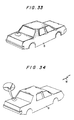
- Figs. 33 and 34 respectively show the magnitude and direction of high-frequency surface currents induced at various different locations of the vehicle body at the frequency of 60 MHz, the values of which are obtained from the measurements of the probe P and the simulation effected by the computer.
- the distribution of surface currents has higher densities at the marginal edge of the vehicle body and lower densities at the central portion of the flat vehicle panels.
- the value of the current decreases in correspondence with the distance from the edge of the metal flat portion of the vehicle body. Since the range under 6 dB is the lower limit for currents in which good sensitivity is actually obtainable, very good sensitivity may be obtained if the pickup is disposed within a distance of 4.5 cm from the peripheral edge.
- the present invention has been made on the basis of the above-described findings, and a high-frequency pickup is disposed at a portion where surface currents flow concentratedly with high density.
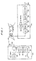
- Fig. 1 shows a first embodiment of a keyless vehicle entry apparatus according to the present invention.
- This embodiment is characterized in that a pickup 102 having a similar structure to the above-described probe is disposed at a front pillar 100 to detect the surface currents which flow concentratedly on the front pillar 100.
- the center of the receiving bands for the pickup 102 is adjusted to be 60 MHz, and the pickup 102 is enabled to receive only high-frequency surface currents in a narrow band by impedance matching, so that the influence of jamming waves such as FM broadcast waves or TV broadcast waves is reduced.
- a keyless vehicle entry apparatus in accordance with this embodiment includes a transmitter 104 which is operated by the user and a receiver 106 provided in the vehicle body, and when the pickup 102 detects the surface currents induced by the electric waves from the transmitter 104, the receiver 106 electrically processes them.
- the transmitter 104 includes a crystal oscillator 108 which has a transmitting frequency of 60 MHz, and an RF amplifier 112 which RF amplifies the transmitting signal to supply it to a transmitting antenna 110, and the RF amplifier 112 is controlled by the keyless entry operation of the user.
- the transmitter 104 includes a key operation switch 114 which is turned on or off by the user, and in accordance with the operation process or operation timing of the switch 114, a code setting circuit 116 receives an electrical input signal.
- the output of the code setting circuit 116 is converted to a desired electrical signal by an encoder 118, and the coded signal controls the output of the RF amplifier 112 through a modulator 120.
- a desired modulated keyless entry signal is transmitted from the transmitting antenna 110 by the keyless entry operation, namely, the operation of the switch 114 by the user.
- the pickup 102 On the vehicle body, high-frequency surface currents are induced by the electric waves from the transmitter 104, and the pickup 102 receives the above-described transmitted keyless entry signal from the surface currents, and supplies it to an RF amplifier 124 of the receiver 106 where it is subjected to a desired amplifying operation.
- the amplified signal is mixed by a mixer 126 with a local oscillating frequency signal of, e.g., 59.545 MHz of a local oscillator 128, and is further amplified by an intermediate frequency amplifier 130.
- a local oscillating frequency signal e.g., 59.545 MHz of a local oscillator 128, and is further amplified by an intermediate frequency amplifier 130.
- the amplified signal is demodulated and detected by a detection circuit 132, and is decoded by a decoder 134 to the code set by the user.
- the receiver 106 outputs the thus decoded keyless entry signal as a control signal 136 which is to be used for locking or unlocking a door, or for other purposes.
- Fig. 2 shows the directional characteristic of the pickup in the 60 MHz frequency band which is provided on the left-hand front pillar of the vehicle body in the first embodiment.
- the pickup has good sensitivity on the right-hand side of the vehicle body, and slightly lowered sensitivity in the forward and backward directions of the vehicle body.
- the keyless vehicle entry apparatus in accordance with this embodiment has good sensitivity on the driver's seat side where there is the greatest likelihood of the keyless entry operation being effected, thereby securing a good operability with respect to keyless entry operation.
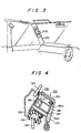
- Fig. 3 is shown the schematic structure of the pickup in accordance with the present invention which is attached to the front pillar.
- the high-frequency pickup 102 is accommodated in the front pillar 100 for supporting the roof panel.
- the high-frequency pickup 102 consists of an electromagnetic type pickup which includes a loop coil.
- the pillar 100 includes a pedestal plate 150 which serves as the main pillar and has a configuration of a hollow prism.
- a windshield molding 152 is secured to the surface of the pedestal plate 150 which faces the exterior of the vehicle body, and the molding 152 retains a front windshield glass 154.
- a weather strip rubber 156 is secured to the surface of the pedestal plate 150 which faces the rear portion of the vehicle body, thereby maintaining the water-sealed state of the joint between a side window glass 158 and the pedestal plate 150.
- a front pillar garnish 160 is mounted on the surface of the pedestal plate 150 which faces the interior of the vehicle body to enclose the surface of the pedestal plate 150, thereby maintaining the aesthetically pleasing appearance of the vehicle body.
- This embodiment is characterized in that a high frequency pickup is longitudinally disposed on the front pillar 100, and in the example shown in Fig. 4, the high-frequency pickup 102 of electromagnetic coupling type is inserted into the hollow portion of the pedestal plate 150.
- the high-frequency pickup 102 is composed of a casing 162 of a conductive material and a loop coil 164 which is provided within the casing 162 and constitutes an antenna element, as is obvious from Figs. 4 and 5.
- the casing 162 for shielding the loop coil from external magnetic flux is provided with an opening 162a at one side thereof.
- the loop coil 164 is exposed from the opening 162a and is disposed in proximity to the pillar where high-frequency surface currents flow concentratedly, in particular, to the pedestal plate 150.
- an opening 150a is provided on a part of the pillar pedestal 150.
- the high-frequency pickup 102 is inserted into the pillar before the front garnish 160 is fixed.
- brackets 166, 168 are fixed to both sides of the casing 162 by spot welding or the like, and the brackets 166, 168 are tightly screwed to the pedestal plate 150.
- the loop coil 164 in this fixed state is disposed in the vicinity of the opening portion 150a of the pedestal plate 150, whereby the magnetic flux induced by the surface currents which flow concentratedly on the pedestal plate 150 are effectively interlinked with the loop coil 164.
- a circuitry 170 including a pre-amplifier and the like is housed behind the loop coil 164 in the casing 162.
- Power source and a signal for controlling the circuit is supplied from a cable 172 to the circuitry 170, and the high-frequency detection signal detected by the loop coil 164 is fetched outward from a coaxial cable 174 and is processed by a circuit similar to that used for examining distribution of surface currents.
- the loop coil 164 is in the form of a single wound coil which is covered with an insulation such that the coil can be arranged in an electrically insulated relationship with and in close contact with the pedestal plate 150.
- the loop coil 164 is attached to the peripheral edge of the pedestal plate 204.
- the front pillar 100 is covered with the front pillar garnish 160.
- the structure of the front pillar 100 is perfectly the same as an ordinary pillar in terms of external appearance.
- the high-frequency surface currents which are concentrated and flow on the front pillar are detected with good efficiency by the loop coil which is longitudinally provided there, thereby ensuring reception in the high-frequency bands without any external exposure of the antenna system.
- an electromagnetic coupling type pickup is used as the high-frequency pickup in this emlodiment, since the keyless entry apparatus according to the present invention is characterized by detection of the surface currents on the pillars for reception of the electric waves from the transmitter, an electrostatic coupling type pickup is also usable as the high frequency pickup as well as the electromagnetic type pickup.
- a detection electrode is longitudinally disposed on the pillar in Figs. 3 and 4 through an air layer or an insulation layer, and a high frequency signal is fetched to the detection electrode side through the electrostatic capacity formed between the surface of the pillar and the detection electrode, thereby making it possible to fetch a high-frequency signal in the carrier frequency of 60 MHz which is used for propagation of the signal in an ordinary keyless entry apparatus.
- a second embodiment of a keyless vehicle entry apparatus according to the present invention will be explained, in which a pickup is longitudinally disposed at the peripheral edge of the engine hood.
- the pickup is disposed on the rear peripheral end portion of the engine hood and its directional characteristic has high sensitivity in the forward direction of the vehicle body.
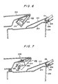
- an engine hood 264 is rotatably supported by the vehicle body at one end thereof, and in its closed state, the inner surface of the peripheral end portion which faces the front windshield glass 154 is opposed to a front outer panel 202.
- the inside of the front outer panel 202 is connected to a front inner panel 204 and the front windshield glass 154 is supported on the front outer panel 202 by a stopper 206.
- a dam 208 is provided between the front windshield glass 154 and the front inner panel 204, thereby preventing the ingress of rainwater or the like.
- a molding 210 is provided.
- a pickup 212 in this embodiment has a similar structure to the high-frequency pickup used in the first embodiment, and includes a casing 214, a loop coil 216 and a circuitry 218.
- This embodiment is characterized in that the pickup 212 is fixed within a distance of 6.0 cm from the peripheral portion, in particular, the peripheral edge of the engine hood which faces the front outer panel 201, whereby it is possible to positively detect the high-frequency surface currents which flow concentratedly with high density on peripheral portion of the engine hood.
- Fig. 7 shows the structure of the pickup 212 in this embodiment which is attached to the engine hood 200
- Fig. 8 is an external view of the high frequency pickup to be attached to the engine hood.
- the detail is approximately the same as that in the first embodiment.
- the pickup 212 is attached to the engine hood 200 by brackets 220 and 222, and a screw 224.
- Power source and a signal for controlling the circuitry are supplied from a cable 226, and a high-frequency detection signal is fetched by a coaxial cable 228.
- a third embodiment of a keyless vehicle entry apparatus according to the present invention will be explained, in which a pickup is disposed at the peripheral portion of the trunk lid.
- the pickup exhibits highly sensitive directivity in the backward direction of the vehicle body.
- a water sealing weather strip 304 is provided between a trunk lid 300 and a rear tray panel 302 so as to prevent the ingress of rainwater or the like from a rear window glass 306.
- a dam 308 provided between the rear window glass 306 and the rear tray panel 302 maintains airtightness and prevents the ingress of rainwater, sound or the like.
- a molding 310 is provided at the lower end of the rear window glass 306 on the external side, as is known.
- the pickup 312 is fixed at the peripheral end portion of the trunk lid 278 which faces the rear tray panel 302, and the pickup 312 consists of an electromagnetic coupling type pickup having a similar structure to that used in the first embodiment.
- the loop coil 314 provided in the pickup 312 is disposed such that the longitudinal direction thereof agrees with the longitudinal direction of the trunk lid 300.
- the loop coil 314 is disposed within a distance of 6.0 cm from the peripheral edge of the trunk lid 300, so that the loop coil 314 catch securely and with high efficiency the surface currents which flow concentratedly on the peripheral portion of the trunk lid 300.
- the loop coil 314 in this embodiment is longitudinally disposed on the peripheral portion of the trunk lid 300.
- the high-frequency pickup in this embodiment is, as is the case with the first embodiment, includes a casing 316 of a conductive material.
- the casing 316 accommodates a loop coil 314 and a circuitry 318, and has an opening 316a which is opposed to the trunk lid 300.
- the magnetic flux alone which is induced by the high-frequency surface currents flowing on the peripheral portion of the trunk lid 300 is introduced into the casing 316, which can safely shield the loop coil 314 from external magnetic flux.
- Power source and a signal are supplied to the circuitry 318 from a cable 320, and a high-frequency detection signal is fetched outward from a coaxial cable 322, and is processed by a circuit similar to that explained in the first embodiment.
- Fig. 10 shows the arrangement of the pickup 312 in accordance with this embodiment to the trunk lid 300.
- the same numerals are provided for those elements which are the same as those shown in Fig. 9, and explanation thereof will be omitted.
- Brackets 324 and 326 are attached to the side surfaces of the casing 316 of the pickup 312 by bolts or the like, and the brackets 324 and 326 are secured to the inner panel of the trunk lid 300 by screws 328, thereby rigidly securing the high-frequency pickup 312 to the inside of the trunk lid 300.
- the high-frequency pickup 312 is preferably constructed as shown in Fig. 11.
- a fourth embodiment of a keyless vehicle entry apparatus according to the present invention will be explained, in which a pickup is provided in the vicinity of the rear roof of a vehicle body.
- the pickup in the keyless vehicle entry apparatus in accordance with this embodiment is disposed at the rear right-hand corner of the roof, the keyless vehicle entry apparatus exhibits good receiving sensitivity on the right-hand side of the vehicle body, namely, on the driver's seat side where it is most likely that the keyless entry operation will be effected.
- the above-described position is a preferred location.
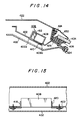
- a metal roof panel 400 which is illustrated in the exposed state is connected to a rear glass window 404 with a rear window frame 402 as its marginal end.
- This embodiment is characterized in that a high-frequency pickup 406 is provided within a distance of 6.0 cm from the edge of the rear window frame 402.
- the pickup 406 includes a casing 408, a loop coil 410, a circuitry 412, a cable 414, a coaxial cable 416 and brackets 418 and 420.
- Fig. 14 is a cross sectional view of the pickup 406 which is fixed to the roof panel.
- the roof panel includes a roof panel 422, to one end of which the rear window frame 402 is secured.
- the rear window glass 404 is secured to the roof panel 422 through a fastener 424 and a dam 426, these two being rigidly bonded by an adhesive 428.
- a molding 430 is fixed between the roof panel 422 and the rear window glass 404.
- An opening 402a for receiving the casing 408 of the pickup 406 is provided on a part of the rear window frame 402 in order that the loop coil 410 of the pickup 406 is opposed to the peripheral portion of the rear window frame 402.
- the casing 408 is provided with an opening 408a such that a longitudinal side of the loop coil 410 is exposed therefrom. In this manner, a part of the loop coil 410 exposed from the casing 408 of a conductive material is opposed in proximity to the peripheral portion of the rear window frame 402.
- a roof garnish 432 is secured to the roof panel, and an edge molding 434 is fixed at the end portions of the roof garnish 432 and the rear window frame 402.
- a keyless entry signal output from the pickup provided in the above-described way is processed in a circuit similar to that in the first embodiment.
- a pickup is disposed on the front roof of a vehicle body.
- the pickup in the keyless vehicle entry apparatus in accordance with this embodiment is disposed at the front right-hand corner of the roof, the keyless vehicle entry apparatus exhibits good receiving sensitivity on the right-hand side of the vehicle body, namely, on the driver's seat side where it is most likely that the keyless entry operation will be effected.
- the above-described position is a preferred location.
- the pickup 500 in this embodiment is disposed in a service hole 502a of the header inner panel 502.
- a front windshield glass 154 is secured to the roof panel 422 through a dam 504, and a molding 508 is fixed between the roof panel 422 and the front windshield glass 154 through a stopper 506, as is known.
- the pickup 500 in this embodiment has a similar structure to that in the first embodiment, and includes a casing 510, a loop coil 512 and a circuitry 514.
- the loop coil 512 of the pickup 500 is secured within a distance of 6.0 cm from the peripheral edge of the header inner panel 502, thereby positively detecting the surface currents which are concentrated with high density on the header inner panel 502.
- a pickup is attached to the trunk lid.
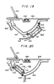
- a trunk hinge 600 with one end thereof rotatably supported by the vehicle body and the other end secured to the trunk lid 602 rotatably supports the trunk lid 602.
- This embodiment is characterized in that a pickup 604 is disposed on the trunk hinge 600.
- a torsion bar 606 is provided on the end of the trunk hinge 600 which is rotatably supported by the vehicle body, so as to control the opening degree of the trunk lid 602 when it is open.
- a water sealing weather strip rubber 608 is provided between the trunk lid 602 and the vehicle body, thereby preventing the ingress of rainwater from a rear window glass 610.
- the pickup 604 is longitudinally fixed on the outer surface of the trunk hinge 600, namely, on the side facing the trunk void, in such a manner that the longitudinal side of a loop coil 612 provided within the pickup 604 is disposed in parallel to the longitudinal side of the trunk hinge 600. In this way, the loop coil 612 can positively catch the surface currents flowing on the trunk hinge 600 with high efficiency.
- the pickup 604 includes a casing 614 and a circuitry 616, as is the case with the first embodiment, and the opening side of the casing 614 is opposed to the trunk hinge 600.
- Brackets 618 and 620 are secured to both open end portions of the casing 614, and one end of each of the brackets 618 and 620 is firmly screwed to the trunk hinge 600.
- the magnetic flux alone which is induced by the high-frequency surface currents flowing on the trunk hinge 600 is introduced into the casing 614, and the pickup is safely shielded from external magnetic flux by the casing 614.
- the loop coil 612 is preferably provided along the trunk hinge 600 and is formed in conformity with the curvature of the trunk hinge 600.
- Power source and a signal for controlling the circuit are supplied to the circuitry 616 from a cable 622, as described above, and the high-frequency detection signal fetched by the loop coil 612 is fetched outward by a coaxial cable 624, and is processed by a similar circuit to that in the first embodiment.
- Fig. 20 shows another example of arrangement for attaching a pickup to the trunk hinge.
- the same numerals are provided for those elements which are the same as those in Fig. 19, and explanation thereof will be omitted.
- a pickup 700 is attached to the back of the trunk hinge 600.
- a casing 702 accommodates a loop coil 704 and a circuitry 706, and is firmly secured to the back of the trunk hinge 600 by brackets 708 and 710.
- the pickup 700 does not protrude from the trunk hinge 600 into the trunk void, whereby it is prevented from coming into contact with or damage the baggage or the like placed within the trunk void.
- Fig. 21 shows a seventh embodiment of a keyless vehicle entry apparatus according to the present invention.
- This embodiment is characterized in that pickups 102a and 102b which have a similar structure to the above-described probe are provided on front pillars 100a and 100b, respectively, on both sides of the vehicle body to detect the surface currents which flow concentratedly on the front pillars.
- the two pickups which are disposed on the respective sides of the vehicle body compensate for each other, thereby enjoying good receiving sensitivity.
- High-frequency surface currents are induced on the vehicle body by the electric waves from the transmitter 104, the pickups 102a and 102b receive a keyless entry signal transmitted from the surface currents.
- the receiving signal of the pickup 102a is input, as it is, into a mixer 123, while the receiving signal of the pickup 102b is input into the mixer 123 after the phase thereof is corrected by a phase difference correction circuit 122.
- the receiving signals are mixed by the mixer 123, and thereafter the mixed signal is supplied into the RF amplifier 124 where it is subjected to a desired amplifying operation.
- Fig. 22 shows the directional patterns of the antenna in the keyless vehicle entry apparatus in accordance with this embodiment in the frequency band of 60 MHz.
- the solid line shows the directional pattern of the pickup 102a and the broken line that of the pickup 102b
- Fig. 22(B) shows the characteristic curve of both pickups as a result of synthesizing the directivities thereof.
- the pickup 102a exhibits good sensitivity on the right-hand side of the vehicle body, and slightly lowered sensitivity in the forward and backward directions of the vehicle body.
- the pickup 102b has a directivity completely contrary to that of the pickup 102a, and it is to be understood that both pickups compensate for each other with respect to sensitivity.
- Fig. 23 shows the directional patterns of the antenna in another embodiment of a keyless vehicle entry apparatus according to the present invention.
- This embodiment is characterized in that pickups are disposed on both rear corners of the roof of a vehicle body.
- both pickups 406a and 406b in this embodiment also compensate for each other's lowered sensitivity, and improve the directional characteristic of the antenna in the keyless vehicle entry apparatus, as in the seventh embodiment shown in Fig. 21.
- Fig. 24 shows the directional patterns of the antenna in still another embodiment of a keyless vehicle entry apparatus according to the present invention.
- This embodiment is characterized in that pickups are disposed at the central portion of the front end of the roof and at the central portion of the rear end of the roof, respectively.
- the pickup 406 disposed at the central portion of the rear end of the roof has a good directional characteristic in the forward direction of the vehicle body, while the pickup 500 disposed at the central portion of the front end of the roof has a good directional characteristic in the backward direction of the vehicle body.
- both pickups compensate for each other's lowered sensitivity, thereby constituting an antenna system producing a good directional characteristic.
- Fig. 25 shows the directional patterns of the antenna in a further embodiment of a keyless vehicle entry apparatus according to the present invention.
- This embodiment is characterized in that pickups are provided on a front pillar and at the central portion of the rear end of the roof.
- the pickup 102b disposed on the front pillar exhibits a good directional characteristic on the right-hand and left-hand sides of the vehicle body, while the pickup 406 disposed at the central portion of the rear end of the roof exhibits a good directional characteristic in the backward and forward directions of the vehicle body.
- both pickups can compensate for each other with respect to the directivity.
- Fig. 26 shows the directional patterns of the antenna in a still further embodiment of a keyless vehicle entry apparatus according to the present invention.
- This embodiment is characterized in that pickups are provided on the right-hand front pillar and on the rear right-hand corner the roof, respectively.
- the directivities of the pickup 102b disposed on the right-hand front pillar and the pickup 406b disposed on the rear right-hand corner of the roof compensate for each other, thereby constituting an antenna system having a good directional characteristic.
- Fig. 27 shows the directional patterns of the antenna in a still further embodiment of a keyless vehicle entry apparatus according to the present invention.
- This embodiment is characterized in that pickups are provided on the front right-hand corner of the roof and the right-hand trunk hinge of the vehicle body, respectively.
- the pickup 500a provided on the front right-hand corner of the roof and the pickup 604 provided on the right-hand trunk hinge compensate for each other with respective to the directivity, thereby constituting an antenna system of a keyless vehicle entry apparatus having a good directional characteristic.
- the number of pickups is not limited to two, and provision of three or more pickups is also preferable.
- the locations of the pickups are not limited to those in the above-described embodiments and may be any positions where it is possible to detect the high-frequency surface currents induced on the vehicle body by the electric waves from the transmitter.
- the present invention it is possible to provide a keyless vehicle entry apparatus provided with pickups exclusively for use by the apparatus without impairing the aesthetically pleasing external appearance, to prevent the radio broadcast receiving sensitivity from being deteriorated by the division of a receiving signal of the radio broadcasting receiving antenna into two, and, in addition, to reduce the influence of jamming waves by limiting the receiving band of a pickup to a narrow one.
Landscapes
- Engineering & Computer Science (AREA)
- Remote Sensing (AREA)
- Computer Networks & Wireless Communication (AREA)
- Physics & Mathematics (AREA)
- General Physics & Mathematics (AREA)
- Computer Security & Cryptography (AREA)
- Radar, Positioning & Navigation (AREA)
- Lock And Its Accessories (AREA)
Applications Claiming Priority (4)
| Application Number | Priority Date | Filing Date | Title |
|---|---|---|---|
| JP175219/85 | 1985-08-09 | ||
| JP60175220A JPS6237476A (ja) | 1985-08-09 | 1985-08-09 | 車両用キ−レスエントリ装置 |
| JP175220/85 | 1985-08-09 | ||
| JP60175219A JPS6237475A (ja) | 1985-08-09 | 1985-08-09 | 車両用キ−レスエントリ装置 |
Publications (2)
| Publication Number | Publication Date |
|---|---|
| EP0214745A1 true EP0214745A1 (de) | 1987-03-18 |
| EP0214745B1 EP0214745B1 (de) | 1991-01-02 |
Family
ID=26496551
Family Applications (1)
| Application Number | Title | Priority Date | Filing Date |
|---|---|---|---|
| EP86305841A Expired - Lifetime EP0214745B1 (de) | 1985-08-09 | 1986-07-30 | Einrichtung für den schlüssellosen Zugang zu einem Fahrzeug |
Country Status (4)
| Country | Link |
|---|---|
| US (1) | US4755823A (de) |
| EP (1) | EP0214745B1 (de) |
| CA (1) | CA1267955A (de) |
| DE (1) | DE3676397D1 (de) |
Cited By (4)
| Publication number | Priority date | Publication date | Assignee | Title |
|---|---|---|---|---|
| EP0343619A3 (en) * | 1988-05-27 | 1990-06-13 | Lectron Products, Inc. | Passive keyless entry system |
| FR2753335A1 (fr) * | 1996-09-11 | 1998-03-13 | Siemens Automotive Sa | Dispositif de blindage d'un circuit electronique |
| US20160297482A1 (en) * | 2015-04-09 | 2016-10-13 | Toyota Jidosha Kabushiki Kaisha | Vehicle upper portion structure |
| US11404768B2 (en) | 2017-07-31 | 2022-08-02 | Yokowo Co., Ltd. | Antenna device and vehicle |
Families Citing this family (15)
| Publication number | Priority date | Publication date | Assignee | Title |
|---|---|---|---|---|
| JP2546842B2 (ja) * | 1987-06-16 | 1996-10-23 | 日産自動車株式会社 | 車両用施解錠制御装置 |
| DE3917897A1 (de) * | 1989-06-01 | 1990-12-06 | Hilmar Dipl Ing Reichel | Geraet zum erzeugen von steuersignalen durch einstrahlung von drahtlos-funk-sendern |
| US5300936A (en) * | 1992-09-30 | 1994-04-05 | Loral Aerospace Corp. | Multiple band antenna |
| JP2824178B2 (ja) * | 1992-11-19 | 1998-11-11 | 株式会社東海理化電機製作所 | 車両用リモートコントロール装置のアンテナ配置方法 |
| DE19752149C2 (de) * | 1997-11-25 | 2003-06-18 | Ford Global Tech Inc | Antennenanordnung für schlüssellose Benutzung eines Fahrzeugs |
| US6072436A (en) * | 1999-01-11 | 2000-06-06 | Lear Automotive Dearborn, Inc. | Incorporation of antenna into vehicle door pillar |
| US6380643B1 (en) * | 1999-11-18 | 2002-04-30 | Siemens Automotive Corporation | Integrated antenna for use with passive entry and ignition system |
| FR2814013B1 (fr) * | 2000-09-13 | 2002-10-11 | Valeo Electronique | Procede de calibrage d'un systeme d'acces mains libres de vehicule automobile |
| US6665983B1 (en) | 2002-07-09 | 2003-12-23 | Fred L. Zimmerman | Lockable sliding window apparatus |
| US7167140B2 (en) * | 2003-07-02 | 2007-01-23 | Nec Tokin Corporation | Coil antenna |
| US20070030121A1 (en) * | 2005-08-08 | 2007-02-08 | Paul Soliz | Remote control for a car's security or keyless entry system that also includes a voice recorder for storing and playing back short audio messages and a method for its use |
| DE102008031762B4 (de) * | 2008-07-04 | 2021-01-28 | Volkswagen Ag | Antennenanordnung und Fahrzeug sowie Verfahren zum Empfang von Funksignalen |
| JP5661372B2 (ja) * | 2010-08-19 | 2015-01-28 | 株式会社アルファ | 車両用ドアハンドル装置 |
| WO2012171212A1 (en) * | 2011-06-17 | 2012-12-20 | Peugeot Citroen Automobiles Sa | Bracket for mounting a hands-free access and start antenna and floor of a vehicle supporting said bracket |
| FR3137632A1 (fr) * | 2022-07-05 | 2024-01-12 | Renault | Support pour toit de véhicule |
Citations (11)
| Publication number | Priority date | Publication date | Assignee | Title |
|---|---|---|---|---|
| DE1949828A1 (de) | 1968-10-04 | 1970-04-30 | Portenseigne Ets Marcel | Verfahren und Vorrichtung zum Empfangen radiofrequenter Signale |
| GB2018482A (en) * | 1978-04-06 | 1979-10-17 | Rossi G | Electronic antitheft device |
| GB2051442A (en) * | 1979-03-30 | 1981-01-14 | Howard J A | A security system |
| JPS5944861A (ja) | 1982-09-07 | 1984-03-13 | Fujitsu Ltd | 半導体装置およびその製造方法 |
| EP0153498A2 (de) * | 1984-03-02 | 1985-09-04 | VDO Adolf Schindling AG | Einrichtung zur berührungslosen fernbedienbaren Türverriegelung, insbesondere einer Zentralverriegelung von Kraftfahrzeugen |
| EP0081765B1 (de) * | 1981-12-11 | 1986-04-02 | Bayerische Motoren Werke Aktiengesellschaft, Patentabteilung AJ-3 | Diebstahlsicherungsvorrichtung für Kraftfahrzeuge |
| EP0180462A2 (de) | 1984-10-29 | 1986-05-07 | Toyota Jidosha Kabushiki Kaisha | Fahrzeugantennensystem |
| EP0181120A2 (de) | 1984-10-26 | 1986-05-14 | Toyota Jidosha Kabushiki Kaisha | Fahrzeugantennensystem |
| EP0182497A1 (de) | 1984-10-17 | 1986-05-28 | Toyota Jidosha Kabushiki Kaisha | Kraftfahrzeugantenne |
| EP0184447A2 (de) * | 1984-12-06 | 1986-06-11 | Toyota Jidosha Kabushiki Kaisha | Fahrzeugantennensystem |
| EP0187446A1 (de) | 1984-10-13 | 1986-07-16 | Toyota Jidosha Kabushiki Kaisha | Kraftfahrzeugantenne |
Family Cites Families (2)
| Publication number | Priority date | Publication date | Assignee | Title |
|---|---|---|---|---|
| JPS5334826A (en) * | 1976-09-10 | 1978-03-31 | Nippon Chem Ind Co Ltd:The | Production of stabilized iron oxide pigment |
| JPS60172804A (ja) * | 1984-10-09 | 1985-09-06 | Toyota Motor Corp | 車両用アンテナ装置 |
-
1986
- 1986-07-28 CA CA000514762A patent/CA1267955A/en not_active Expired
- 1986-07-30 DE DE8686305841T patent/DE3676397D1/de not_active Expired - Lifetime
- 1986-07-30 EP EP86305841A patent/EP0214745B1/de not_active Expired - Lifetime
- 1986-08-04 US US06/893,087 patent/US4755823A/en not_active Expired - Lifetime
Patent Citations (11)
| Publication number | Priority date | Publication date | Assignee | Title |
|---|---|---|---|---|
| DE1949828A1 (de) | 1968-10-04 | 1970-04-30 | Portenseigne Ets Marcel | Verfahren und Vorrichtung zum Empfangen radiofrequenter Signale |
| GB2018482A (en) * | 1978-04-06 | 1979-10-17 | Rossi G | Electronic antitheft device |
| GB2051442A (en) * | 1979-03-30 | 1981-01-14 | Howard J A | A security system |
| EP0081765B1 (de) * | 1981-12-11 | 1986-04-02 | Bayerische Motoren Werke Aktiengesellschaft, Patentabteilung AJ-3 | Diebstahlsicherungsvorrichtung für Kraftfahrzeuge |
| JPS5944861A (ja) | 1982-09-07 | 1984-03-13 | Fujitsu Ltd | 半導体装置およびその製造方法 |
| EP0153498A2 (de) * | 1984-03-02 | 1985-09-04 | VDO Adolf Schindling AG | Einrichtung zur berührungslosen fernbedienbaren Türverriegelung, insbesondere einer Zentralverriegelung von Kraftfahrzeugen |
| EP0187446A1 (de) | 1984-10-13 | 1986-07-16 | Toyota Jidosha Kabushiki Kaisha | Kraftfahrzeugantenne |
| EP0182497A1 (de) | 1984-10-17 | 1986-05-28 | Toyota Jidosha Kabushiki Kaisha | Kraftfahrzeugantenne |
| EP0181120A2 (de) | 1984-10-26 | 1986-05-14 | Toyota Jidosha Kabushiki Kaisha | Fahrzeugantennensystem |
| EP0180462A2 (de) | 1984-10-29 | 1986-05-07 | Toyota Jidosha Kabushiki Kaisha | Fahrzeugantennensystem |
| EP0184447A2 (de) * | 1984-12-06 | 1986-06-11 | Toyota Jidosha Kabushiki Kaisha | Fahrzeugantennensystem |
Cited By (5)
| Publication number | Priority date | Publication date | Assignee | Title |
|---|---|---|---|---|
| EP0343619A3 (en) * | 1988-05-27 | 1990-06-13 | Lectron Products, Inc. | Passive keyless entry system |
| FR2753335A1 (fr) * | 1996-09-11 | 1998-03-13 | Siemens Automotive Sa | Dispositif de blindage d'un circuit electronique |
| US20160297482A1 (en) * | 2015-04-09 | 2016-10-13 | Toyota Jidosha Kabushiki Kaisha | Vehicle upper portion structure |
| US9731771B2 (en) * | 2015-04-09 | 2017-08-15 | Toyota Jidosha Kabushiki Kaisha | Vehicle upper portion structure |
| US11404768B2 (en) | 2017-07-31 | 2022-08-02 | Yokowo Co., Ltd. | Antenna device and vehicle |
Also Published As
| Publication number | Publication date |
|---|---|
| EP0214745B1 (de) | 1991-01-02 |
| US4755823A (en) | 1988-07-05 |
| DE3676397D1 (de) | 1991-02-07 |
| CA1267955C (en) | 1990-04-17 |
| CA1267955A (en) | 1990-04-17 |
Similar Documents
| Publication | Publication Date | Title |
|---|---|---|
| US4755823A (en) | Keyless vehicle entry apparatus | |
| US4823142A (en) | Automobile antenna system | |
| US4819001A (en) | Automobile antenna system | |
| EP0182497B1 (de) | Kraftfahrzeugantenne | |
| EP0191233B1 (de) | Kraftfahrzeugantennensystem | |
| US4811330A (en) | Automobile antenna system | |
| US4707701A (en) | Automobile antenna system | |
| US4788549A (en) | Automotive antenna system | |
| US4717920A (en) | Automobile antenna system | |
| US4821042A (en) | Vehicle antenna system | |
| JPH053507B2 (de) | ||
| EP0180462B1 (de) | Fahrzeugantennensystem | |
| JPS61136304A (ja) | 自動車用アンテナ装置 | |
| JP3236326B2 (ja) | 車両用アンテナ装置 | |
| US4806942A (en) | Automobile TV antenna system | |
| DK171851B1 (da) | Antennesystem til biler | |
| JPS6237476A (ja) | 車両用キ−レスエントリ装置 | |
| JP2007153019A (ja) | ドア内蔵車載アンテナ | |
| JPS61120534A (ja) | 車両用アンテナ装置 | |
| JPS61129904A (ja) | 自動車用アンテナ装置 | |
| JPH0215702A (ja) | 自動車用窓ガラスアンテナ | |
| JPS61120503A (ja) | 車両用アンテナ装置 | |
| JPS61112403A (ja) | 自動車用アンテナ装置 | |
| JPS623507A (ja) | 自動車用アンテナ装置 | |
| JPS61127205A (ja) | 自動車用アンテナ装置 |
Legal Events
| Date | Code | Title | Description |
|---|---|---|---|
| PUAI | Public reference made under article 153(3) epc to a published international application that has entered the european phase |
Free format text: ORIGINAL CODE: 0009012 |
|
| AK | Designated contracting states |
Kind code of ref document: A1 Designated state(s): DE GB |
|
| 17P | Request for examination filed |
Effective date: 19870424 |
|
| 17Q | First examination report despatched |
Effective date: 19890704 |
|
| GRAA | (expected) grant |
Free format text: ORIGINAL CODE: 0009210 |
|
| AK | Designated contracting states |
Kind code of ref document: B1 Designated state(s): DE GB |
|
| REF | Corresponds to: |
Ref document number: 3676397 Country of ref document: DE Date of ref document: 19910207 |
|
| PLBE | No opposition filed within time limit |
Free format text: ORIGINAL CODE: 0009261 |
|
| STAA | Information on the status of an ep patent application or granted ep patent |
Free format text: STATUS: NO OPPOSITION FILED WITHIN TIME LIMIT |
|
| 26N | No opposition filed | ||
| PGFP | Annual fee paid to national office [announced via postgrant information from national office to epo] |
Ref country code: GB Payment date: 19990728 Year of fee payment: 14 |
|
| PG25 | Lapsed in a contracting state [announced via postgrant information from national office to epo] |
Ref country code: GB Free format text: LAPSE BECAUSE OF NON-PAYMENT OF DUE FEES Effective date: 20000730 |
|
| GBPC | Gb: european patent ceased through non-payment of renewal fee |
Effective date: 20000730 |
|
| PGFP | Annual fee paid to national office [announced via postgrant information from national office to epo] |
Ref country code: DE Payment date: 20020807 Year of fee payment: 17 |
|
| PG25 | Lapsed in a contracting state [announced via postgrant information from national office to epo] |
Ref country code: DE Free format text: LAPSE BECAUSE OF NON-PAYMENT OF DUE FEES Effective date: 20040203 |