EP0215460A2 - Procédé et appareil pour la fabrication de polyesters - Google Patents
Procédé et appareil pour la fabrication de polyesters Download PDFInfo
- Publication number
- EP0215460A2 EP0215460A2 EP86112684A EP86112684A EP0215460A2 EP 0215460 A2 EP0215460 A2 EP 0215460A2 EP 86112684 A EP86112684 A EP 86112684A EP 86112684 A EP86112684 A EP 86112684A EP 0215460 A2 EP0215460 A2 EP 0215460A2
- Authority
- EP
- European Patent Office
- Prior art keywords
- stirring vane
- tank
- lower disk
- tank wall
- set forth
- Prior art date
- Legal status (The legal status is an assumption and is not a legal conclusion. Google has not performed a legal analysis and makes no representation as to the accuracy of the status listed.)
- Granted
Links
- 229920000728 polyester Polymers 0.000 title claims abstract description 16
- 238000000034 method Methods 0.000 title claims abstract description 13
- 230000008569 process Effects 0.000 title claims abstract description 9
- 238000002360 preparation method Methods 0.000 title claims abstract description 4
- 238000003756 stirring Methods 0.000 claims abstract description 68
- 238000006116 polymerization reaction Methods 0.000 claims abstract description 36
- 239000010409 thin film Substances 0.000 claims abstract description 23
- 239000000178 monomer Substances 0.000 claims abstract description 7
- 239000012295 chemical reaction liquid Substances 0.000 claims description 19
- 230000002093 peripheral effect Effects 0.000 claims description 13
- 230000008093 supporting effect Effects 0.000 claims description 10
- 239000011261 inert gas Substances 0.000 claims description 8
- 238000004519 manufacturing process Methods 0.000 claims description 6
- 229920000642 polymer Polymers 0.000 description 42
- LYCAIKOWRPUZTN-UHFFFAOYSA-N Ethylene glycol Chemical compound OCCO LYCAIKOWRPUZTN-UHFFFAOYSA-N 0.000 description 19
- 238000006243 chemical reaction Methods 0.000 description 15
- WOZVHXUHUFLZGK-UHFFFAOYSA-N dimethyl terephthalate Chemical compound COC(=O)C1=CC=C(C(=O)OC)C=C1 WOZVHXUHUFLZGK-UHFFFAOYSA-N 0.000 description 12
- 230000036632 reaction speed Effects 0.000 description 12
- 239000000126 substance Substances 0.000 description 11
- IJGRMHOSHXDMSA-UHFFFAOYSA-N Atomic nitrogen Chemical compound N#N IJGRMHOSHXDMSA-UHFFFAOYSA-N 0.000 description 8
- KKEYFWRCBNTPAC-UHFFFAOYSA-N Terephthalic acid Chemical compound OC(=O)C1=CC=C(C(O)=O)C=C1 KKEYFWRCBNTPAC-UHFFFAOYSA-N 0.000 description 8
- 230000009471 action Effects 0.000 description 6
- 230000015572 biosynthetic process Effects 0.000 description 6
- 229910001873 dinitrogen Inorganic materials 0.000 description 6
- 230000007246 mechanism Effects 0.000 description 6
- -1 polyethylene terephthalate Polymers 0.000 description 6
- 238000010008 shearing Methods 0.000 description 6
- 150000002148 esters Chemical class 0.000 description 5
- 238000010438 heat treatment Methods 0.000 description 4
- 229920000139 polyethylene terephthalate Polymers 0.000 description 4
- 239000005020 polyethylene terephthalate Substances 0.000 description 4
- 238000007789 sealing Methods 0.000 description 4
- 238000005809 transesterification reaction Methods 0.000 description 4
- OKKJLVBELUTLKV-UHFFFAOYSA-N Methanol Chemical compound OC OKKJLVBELUTLKV-UHFFFAOYSA-N 0.000 description 3
- 125000003178 carboxy group Chemical group [H]OC(*)=O 0.000 description 3
- 239000000835 fiber Substances 0.000 description 3
- 239000010408 film Substances 0.000 description 3
- 239000000463 material Substances 0.000 description 3
- 239000000047 product Substances 0.000 description 3
- OFOBLEOULBTSOW-UHFFFAOYSA-N Malonic acid Chemical compound OC(=O)CC(O)=O OFOBLEOULBTSOW-UHFFFAOYSA-N 0.000 description 2
- NBIIXXVUZAFLBC-UHFFFAOYSA-N Phosphoric acid Chemical compound OP(O)(O)=O NBIIXXVUZAFLBC-UHFFFAOYSA-N 0.000 description 2
- WNLRTRBMVRJNCN-UHFFFAOYSA-N adipic acid Chemical compound OC(=O)CCCCC(O)=O WNLRTRBMVRJNCN-UHFFFAOYSA-N 0.000 description 2
- ADCOVFLJGNWWNZ-UHFFFAOYSA-N antimony trioxide Chemical compound O=[Sb]O[Sb]=O ADCOVFLJGNWWNZ-UHFFFAOYSA-N 0.000 description 2
- WERYXYBDKMZEQL-UHFFFAOYSA-N butane-1,4-diol Chemical compound OCCCCO WERYXYBDKMZEQL-UHFFFAOYSA-N 0.000 description 2
- 239000006227 byproduct Substances 0.000 description 2
- 239000003054 catalyst Substances 0.000 description 2
- 239000007795 chemical reaction product Substances 0.000 description 2
- 230000000052 comparative effect Effects 0.000 description 2
- 230000002950 deficient Effects 0.000 description 2
- 238000010586 diagram Methods 0.000 description 2
- WGCNASOHLSPBMP-UHFFFAOYSA-N hydroxyacetaldehyde Natural products OCC=O WGCNASOHLSPBMP-UHFFFAOYSA-N 0.000 description 2
- 238000010348 incorporation Methods 0.000 description 2
- QQVIHTHCMHWDBS-UHFFFAOYSA-N isophthalic acid Chemical compound OC(=O)C1=CC=CC(C(O)=O)=C1 QQVIHTHCMHWDBS-UHFFFAOYSA-N 0.000 description 2
- XNGIFLGASWRNHJ-UHFFFAOYSA-N phthalic acid Chemical compound OC(=O)C1=CC=CC=C1C(O)=O XNGIFLGASWRNHJ-UHFFFAOYSA-N 0.000 description 2
- 239000011295 pitch Substances 0.000 description 2
- 238000006068 polycondensation reaction Methods 0.000 description 2
- 239000011541 reaction mixture Substances 0.000 description 2
- CXMXRPHRNRROMY-UHFFFAOYSA-N sebacic acid Chemical compound OC(=O)CCCCCCCCC(O)=O CXMXRPHRNRROMY-UHFFFAOYSA-N 0.000 description 2
- ISPYQTSUDJAMAB-UHFFFAOYSA-N 2-chlorophenol Chemical compound OC1=CC=CC=C1Cl ISPYQTSUDJAMAB-UHFFFAOYSA-N 0.000 description 1
- OKTJSMMVPCPJKN-UHFFFAOYSA-N Carbon Chemical compound [C] OKTJSMMVPCPJKN-UHFFFAOYSA-N 0.000 description 1
- 150000001242 acetic acid derivatives Chemical class 0.000 description 1
- ZOIORXHNWRGPMV-UHFFFAOYSA-N acetic acid;zinc Chemical compound [Zn].CC(O)=O.CC(O)=O ZOIORXHNWRGPMV-UHFFFAOYSA-N 0.000 description 1
- 239000001361 adipic acid Substances 0.000 description 1
- 235000011037 adipic acid Nutrition 0.000 description 1
- 238000013019 agitation Methods 0.000 description 1
- 125000001931 aliphatic group Chemical group 0.000 description 1
- 125000005907 alkyl ester group Chemical group 0.000 description 1
- 125000000217 alkyl group Chemical group 0.000 description 1
- 229910000147 aluminium phosphate Inorganic materials 0.000 description 1
- 125000003118 aryl group Chemical group 0.000 description 1
- 230000004888 barrier function Effects 0.000 description 1
- 150000001558 benzoic acid derivatives Chemical class 0.000 description 1
- 229910052799 carbon Inorganic materials 0.000 description 1
- BVKZGUZCCUSVTD-UHFFFAOYSA-N carbonic acid Chemical compound OC(O)=O BVKZGUZCCUSVTD-UHFFFAOYSA-N 0.000 description 1
- 230000008859 change Effects 0.000 description 1
- 150000001875 compounds Chemical class 0.000 description 1
- 238000010276 construction Methods 0.000 description 1
- 238000000354 decomposition reaction Methods 0.000 description 1
- 150000002009 diols Chemical class 0.000 description 1
- 239000006185 dispersion Substances 0.000 description 1
- 238000004821 distillation Methods 0.000 description 1
- 230000000694 effects Effects 0.000 description 1
- 230000032050 esterification Effects 0.000 description 1
- 238000005886 esterification reaction Methods 0.000 description 1
- 238000001704 evaporation Methods 0.000 description 1
- 230000008020 evaporation Effects 0.000 description 1
- 239000007789 gas Substances 0.000 description 1
- 150000004820 halides Chemical class 0.000 description 1
- 150000002484 inorganic compounds Chemical class 0.000 description 1
- 229910010272 inorganic material Inorganic materials 0.000 description 1
- 238000009413 insulation Methods 0.000 description 1
- 150000002681 magnesium compounds Chemical class 0.000 description 1
- 229940071125 manganese acetate Drugs 0.000 description 1
- 150000002697 manganese compounds Chemical class 0.000 description 1
- UOGMEBQRZBEZQT-UHFFFAOYSA-L manganese(2+);diacetate Chemical compound [Mn+2].CC([O-])=O.CC([O-])=O UOGMEBQRZBEZQT-UHFFFAOYSA-L 0.000 description 1
- 238000002156 mixing Methods 0.000 description 1
- 239000000203 mixture Substances 0.000 description 1
- KYTZHLUVELPASH-UHFFFAOYSA-N naphthalene-1,2-dicarboxylic acid Chemical compound C1=CC=CC2=C(C(O)=O)C(C(=O)O)=CC=C21 KYTZHLUVELPASH-UHFFFAOYSA-N 0.000 description 1
- 229910052757 nitrogen Inorganic materials 0.000 description 1
- 238000005192 partition Methods 0.000 description 1
- 239000002685 polymerization catalyst Substances 0.000 description 1
- 230000002035 prolonged effect Effects 0.000 description 1
- 230000001737 promoting effect Effects 0.000 description 1
- IUVKMZGDUIUOCP-BTNSXGMBSA-N quinbolone Chemical class O([C@H]1CC[C@H]2[C@H]3[C@@H]([C@]4(C=CC(=O)C=C4CC3)C)CC[C@@]21C)C1=CCCC1 IUVKMZGDUIUOCP-BTNSXGMBSA-N 0.000 description 1
- 239000000376 reactant Substances 0.000 description 1
- 229940102098 revolution Drugs 0.000 description 1
- YGSDEFSMJLZEOE-UHFFFAOYSA-N salicylic acid Chemical class OC(=O)C1=CC=CC=C1O YGSDEFSMJLZEOE-UHFFFAOYSA-N 0.000 description 1
- 238000000926 separation method Methods 0.000 description 1
- 239000007787 solid Substances 0.000 description 1
- 239000002904 solvent Substances 0.000 description 1
- 239000004753 textile Substances 0.000 description 1
- 229920001169 thermoplastic Polymers 0.000 description 1
- 239000004246 zinc acetate Substances 0.000 description 1
- 150000003752 zinc compounds Chemical class 0.000 description 1
Images



Classifications
-
- B—PERFORMING OPERATIONS; TRANSPORTING
- B01—PHYSICAL OR CHEMICAL PROCESSES OR APPARATUS IN GENERAL
- B01J—CHEMICAL OR PHYSICAL PROCESSES, e.g. CATALYSIS OR COLLOID CHEMISTRY; THEIR RELEVANT APPARATUS
- B01J19/00—Chemical, physical or physico-chemical processes in general; Their relevant apparatus
- B01J19/18—Stationary reactors having moving elements inside
-
- B—PERFORMING OPERATIONS; TRANSPORTING
- B01—PHYSICAL OR CHEMICAL PROCESSES OR APPARATUS IN GENERAL
- B01F—MIXING, e.g. DISSOLVING, EMULSIFYING OR DISPERSING
- B01F27/00—Mixers with rotary stirring devices in fixed receptacles; Kneaders
- B01F27/80—Mixers with rotary stirring devices in fixed receptacles; Kneaders with stirrers rotating about a substantially vertical axis
- B01F27/95—Mixers with rotary stirring devices in fixed receptacles; Kneaders with stirrers rotating about a substantially vertical axis with stirrers having planetary motion, i.e. rotating about their own axis and about a sun axis
-
- C—CHEMISTRY; METALLURGY
- C08—ORGANIC MACROMOLECULAR COMPOUNDS; THEIR PREPARATION OR CHEMICAL WORKING-UP; COMPOSITIONS BASED THEREON
- C08G—MACROMOLECULAR COMPOUNDS OBTAINED OTHERWISE THAN BY REACTIONS ONLY INVOLVING UNSATURATED CARBON-TO-CARBON BONDS
- C08G63/00—Macromolecular compounds obtained by reactions forming a carboxylic ester link in the main chain of the macromolecule
- C08G63/78—Preparation processes
-
- C—CHEMISTRY; METALLURGY
- C08—ORGANIC MACROMOLECULAR COMPOUNDS; THEIR PREPARATION OR CHEMICAL WORKING-UP; COMPOSITIONS BASED THEREON
- C08G—MACROMOLECULAR COMPOUNDS OBTAINED OTHERWISE THAN BY REACTIONS ONLY INVOLVING UNSATURATED CARBON-TO-CARBON BONDS
- C08G63/00—Macromolecular compounds obtained by reactions forming a carboxylic ester link in the main chain of the macromolecule
- C08G63/78—Preparation processes
- C08G63/785—Preparation processes characterised by the apparatus used
-
- B—PERFORMING OPERATIONS; TRANSPORTING
- B01—PHYSICAL OR CHEMICAL PROCESSES OR APPARATUS IN GENERAL
- B01F—MIXING, e.g. DISSOLVING, EMULSIFYING OR DISPERSING
- B01F27/00—Mixers with rotary stirring devices in fixed receptacles; Kneaders
- B01F27/05—Stirrers
- B01F27/11—Stirrers characterised by the configuration of the stirrers
- B01F27/114—Helically shaped stirrers, i.e. stirrers comprising a helically shaped band or helically shaped band sections
- B01F27/1143—Helically shaped stirrers, i.e. stirrers comprising a helically shaped band or helically shaped band sections screw-shaped, e.g. worms
-
- B—PERFORMING OPERATIONS; TRANSPORTING
- B01—PHYSICAL OR CHEMICAL PROCESSES OR APPARATUS IN GENERAL
- B01F—MIXING, e.g. DISSOLVING, EMULSIFYING OR DISPERSING
- B01F27/00—Mixers with rotary stirring devices in fixed receptacles; Kneaders
- B01F27/23—Mixers with rotary stirring devices in fixed receptacles; Kneaders characterised by the orientation or disposition of the rotor axis
- B01F27/232—Mixers with rotary stirring devices in fixed receptacles; Kneaders characterised by the orientation or disposition of the rotor axis with two or more rotation axes
- B01F27/2324—Mixers with rotary stirring devices in fixed receptacles; Kneaders characterised by the orientation or disposition of the rotor axis with two or more rotation axes planetary
-
- B—PERFORMING OPERATIONS; TRANSPORTING
- B01—PHYSICAL OR CHEMICAL PROCESSES OR APPARATUS IN GENERAL
- B01J—CHEMICAL OR PHYSICAL PROCESSES, e.g. CATALYSIS OR COLLOID CHEMISTRY; THEIR RELEVANT APPARATUS
- B01J2219/00—Chemical, physical or physico-chemical processes in general; Their relevant apparatus
- B01J2219/00049—Controlling or regulating processes
- B01J2219/00051—Controlling the temperature
- B01J2219/00074—Controlling the temperature by indirect heating or cooling employing heat exchange fluids
- B01J2219/00087—Controlling the temperature by indirect heating or cooling employing heat exchange fluids with heat exchange elements outside the reactor
- B01J2219/00094—Jackets
-
- B—PERFORMING OPERATIONS; TRANSPORTING
- B01—PHYSICAL OR CHEMICAL PROCESSES OR APPARATUS IN GENERAL
- B01J—CHEMICAL OR PHYSICAL PROCESSES, e.g. CATALYSIS OR COLLOID CHEMISTRY; THEIR RELEVANT APPARATUS
- B01J2219/00—Chemical, physical or physico-chemical processes in general; Their relevant apparatus
- B01J2219/00049—Controlling or regulating processes
- B01J2219/00168—Controlling or regulating processes controlling the viscosity
-
- B—PERFORMING OPERATIONS; TRANSPORTING
- B01—PHYSICAL OR CHEMICAL PROCESSES OR APPARATUS IN GENERAL
- B01J—CHEMICAL OR PHYSICAL PROCESSES, e.g. CATALYSIS OR COLLOID CHEMISTRY; THEIR RELEVANT APPARATUS
- B01J2219/00—Chemical, physical or physico-chemical processes in general; Their relevant apparatus
- B01J2219/18—Details relating to the spatial orientation of the reactor
- B01J2219/185—Details relating to the spatial orientation of the reactor vertical
Definitions
- the present invention relates to a process for preparing polyesters, especially polyethylene terephthalate, by continuously carrying out polymerization by using a thin film polymerization apparatus, and also to an apparatus for use in the practice of this process.
- Synthetic polyester polymers have excellent physical and chemical properties, and are widely used in various fields. Especially, polyethylene terephthalate has an excellent chemical resistance, heat resistance, insulation resistance, gas barrier property, tenacity, and elasticity modulus and is used in large quantities for textile fibers, industrial fibers, films, containers, and ordinary shaped articles. In order to enjoy greater advantages and reduce production costs, the changeover of batchwise polymerization to continuous polymerization has been tried and advanced. Since the uses of polyesters have been recently diversified, it is now necessary to produce a variety of polymers suitable for respective uses, individually and in small quantities.
- a process for preparing a polyester by continuous melt polymerization wherein a thin film polymerization apparatus having at least one columnar or cylindrical roller-shaped stirring vane rotating along and in close proximity to a substantially cylindrical vertical tank wall is used, and the stirring vane is caused to make an epicyclic movement along the tank wall in the circumferential direction thereof so that the direction of rotation is the same as the direction of revolution, and a polyester-forming monomer and/or an oligomer thereof is dropped on the surface of the tank wall in the form of a thin film.
- an apparatus for the preparation of a polyester which comprises a thin film polymerization tank having at least one columnar or cylindrical roller-shaped stirring vane rotating along and in close proximity to a substantially cylindrical vertical tank wall, wherein, in the upper portion of the tank, a circumscribed type main gear, an upper disk, and a lower disk are arranged, in this order from above, a main driving shaft is disposed to pierce through the centers of the main gear, upper disk, and lower disk, the main driving shaft is freely fitted to the main gear, at least one of the upper and lower disks is secured to the main driving shaft, at least one supporting shaft is vertically rotatably disposed on the upper and lower disks, and an epicyclic gear to be engaged with the main gear is attached to the top end portion of the supporting shaft and the stirring vane is disposed in the lower portion of the supporting shaft.
- the present invention is characterized in that in carrying out continuous polymerization by introducing a polyester-forming monomer and/or an oligomer thereof into a longitudinal reaction vessel heated and maintained under vacuum, a columnar or cylindrical roller-shaped stirring vane is caused to make an epicyclic movement along the tank wall in the circumferential direction thereof so that the direction of rotation is the same as the direction of revolution, whereby a thin film is formed on the tank wall and stirring vane.
- peripheral speed of the sum of the rotation speed and revolution speed of the stirring vane to the tank wall is at least 0.3 m/sec and the clearance between the tank wall and the stirring vane is not larger than 5 mm, preferably 0.5 to 5 mm, effective shearing can be imparted to a polymer present between the tank wall and the stirring vane at a high speed, and the reaction can be greatly increased and the stirring vane is entirely wetted to substantially completely prevent the formation of dead spaces.
- a rake-down groove structure be formed on the stirring vane.
- a groove having a rake-up structure can be formed.
- the stirring power can be reduced and, simultaneously, the durability of the bearing as the stirring vane-supporting member, which has a relatively short life, can be greatly improved.
- a stirring vane having an inverted cone shape is used and the clearance between the stirring vane and the tank wall is 0.5 to 5 mm in the upper portion and l to l0 mm in the lower portion.
- an opening for introducing an inert gas from above the lower disk is disposed, a plurality of inert gas flow-in holes formed through the lower disk, and a plate-like baffle disposed below and in close proximity to the flow-in holes so that the inert gas flows out and diffuses along the lower face of the lower disk.
- the polyester referred to in the present invention is mainly directed to polyethylene terephthalate obtained by subjecting terephthalic acid or a dialkyl ester of terephthalic acid (the carbon number of the alkyl group is ordinarily l to 4) and ethylene glycol to esterification or transesterification reaction and polycondensation.
- a part (ordinarily up to 20 mole%) of terephthalic acid or the dialkyl ester of terephthalic acid may be substituted by a hydroxycarboxylic acid, for example, an aromatic dicarboxylic acid such as isophthalic acid, phthalic acid or naphthalene-dicarboxylic acid or an aliphatic dicarboxylic acid such as adipic acid or sebacic acid, or an alkyl ester thereof.
- a part or all of ethylene glycol may be substituted by a glycol represented by the formula HO(CH2 n OH (in which n is an integer of from 3 to l0), such as porpylene glycol or tetramethylene glycol.
- a manganese compound, a zinc compound or a magnesium compound is used as the ester exchange catalyst.
- the kind of the ester exchange catalyst is not particularly critical and any of compounds having an ester exchange capacity can be used.
- inorganic compounds such as halides and oxides and organic acid salts are used.
- An organic acid salt such as an acetic acid salt, a propionic acid salt, a salicylic acid salt or a benzoic acid salt is preferably used.
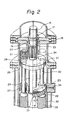
- a cylindrical tank ll has a shaft sealing chamber l4 in the upper portion and a withdrawal chamber 36 in the lower portion, and substantially all of the periphery of the tank ll is surrounded by an outer cylinder l2 and a heating jacket chamber l3 is formed between the tank ll and the outer cylinder l2.
- a driving shaft l5 piercing through the central portion is rotatably supported in the shaft sealing chamber l4 through a bearing l6, and the top end of the driving shaft l5 is connected to a driving member directly through a pulley (not shown) or the like.
- Sealing means l7 such as a mechanical seal is disposed on the lower end of the shaft sealing chamber l4 to seal the tank ll so that it can resist high vacuum.
- a stationary main gear 20 secured to a partition plate l8 through a bolt l9 or the like and upper and lower disks 2l and 22 having a size such that they are in close proximity to the inner wall of the tank ll are arranged, in this order from above, at predetermined intervals.
- Through holes 23, 24, and 25 are formed in the main gear 20 and the upper and lower disks 2l and 22, respectively, and the driving shaft l5 pierces these through holes 23 to 25 and the lower end of the driving shaft l5 reaches the lower disk 22 (the driving shaft l5 may also pierce through the lower disk 22).
- the driving shaft l5 has no contact with the main gear 20 but pierces the main gear 20 in the freely fitted state.
- the upper and lower disks 2l and 22 are secured and integrated by a key or the like (not shown). Preferably this fixation is carried out for both of the upper and lower disks 2l and 22, but only one need be fixed, if desired.
- a plurality of through holes 26 or 27 (6 holes formed equidistantly in Fig. l) are formed in each of the upper and lower disks 2l and 22.
- a supporting shaft 30 is rotatably held through these through holes 26 and 27 via bearings 28 and 29 arranged in the through holes 26 and 27.
- An epicyclic gear 3l to be engaged with the main gear 20 is secured to the top end of the supporting shaft 30, and a columnar roller-shaped stirring vane 32 is connected to the lower portion of the supporting shaft 30 below the lower disk 22, so that the stirring vane 32 is in close proximity to the inner wall of the tank.
- at least two stirring vanes 32 (supporting shafts 30) are equidistantly disposed, but only one stirring vane need be disposed, if desired.
- a reaction liquid feed nozzle 34 is arranged on the inner wall of the tank at the position confronting the side periphery of the lower disk 22, so that a reaction liquid fed from the feed nozzle 34 abuts against the concave-convex side periphery of the lower disk 22 and is thus dispersed. Accordingly, the lower disk 22 acts as a polymer-dispersing member.
- the oblique grooves (convex-concave parts) 33 for dispersing the polymer are formed so that a downward force is given to the reaction liquid according to rotation, and the angle ⁇ is preferably l0° to 30°.
- a spiral groove 35 is formed along the entire circumference of the stirring vane 32 so as to produce a downward feed action.
- a spiral groove extending in a reverse direction so as to perform a rake-up action may be formed.
- the spiral groove 35 (or the concave part) is formed so that the angle ⁇ to the vertical line is preferably 8° to 40°, especially preferably l0° to 30°.
- the groove 35 is discontinuous rather than continuous.
- the groove 35 is discontinuous with a length corresponding to about l.5 circumferences.
- the stirring vane 32 is arranged so that it can rotate in close proximity to the inner wall of the tank, and the distance between the stirring vane 32 and the inner wall of the tank, that is, the clearance between the outer diameter (the convex part in the case where the groove 35 is formed) of the stirring vane 32 and the inner wall of the tank is not larger than 5 mm, preferivelyably 0.5 to 5 mm, especially preferably 0.5 to 3 mm. If this clearance exceeds 5 mm, short paths are readily formed, the reaction speed is not increased, and dead spaces are likely to be formed.
- the stirring vane 32 is caused to make an epicyclic movement such that the direction of rotation is the same as the direction of revolution, and the peripheral speed of the stirring vane, that is, the sum of the rotation speed and revolution speed, is at least 0.3 m/sec, especially at least 0.5 m/sec. If an epicyclic movement is carried out at a peripheral speed lower than 0.3 m/sec, the reaction is not sufficiently advanced and it is often impossible to stably obtain a product having an excellent quality.
- the reaction liquid withdrawal chamber 36 located in the lower portion of the tank ll has a reaction liquid withdrawal nozzle 37 arranged on the lower end thereof and a vacuum suction nozzle 38 arranged in the side portion thereof.
- the driving shaft l5 when the driving shaft l5 is rotated by driving means (not shown), the upper and lower disks 2l and 22 are rotated in the direction indicated by an arrow.
- the epicyclic gear 3l is engaged with the main gear 20, and the epicycle gear 3l revolves around the main gear 20 and rotates around its own axis.
- the stirring vane 32 makes an epicyclic movement in close proximity to the inner wall of the tank along the inner wall of the tank such that the direction of rotation is the same as the direction of revolution.
- the tank ll and withdrawal chamber 36 are heated at a predetermined temperature by heating means such as a heating medium in the jacket l3, and simultaneously, a high vacuum is maintained in the tank ll and withdrawal chamber 36 through the nozzle 38 communicating with a vacuum generating means.
- the reaction liquid (monomer, premopolymer or polymer) supplied from the nozzle 34 arranged in the upper portion of the tank is distributed substantially uniformly in the circumferential direction by the lower disk 22 and is coated on the inner wall of the tank.
- the polymer flows down while receiving a shearing action from the stirring vane 32 revolving and rotating in the same direction as the revolution direction.
- the polymer coated on the inner wall of the tank always moves downward in the state where the surface is always renewed and undergoes effective shearing by the clearance between the stirring vane and the wall face.
- Surface renewal is very rapidly effected in the polymer present on the surface of the stirring vane 32 to form a filmy reaction surface, and the reaction is advanced very rapidly.
- Another merit of the present invention is that the vane is entirely wetted and a so-called dead space is not formed.
- a reaction vessel 3 having a central shaft l and a stirring vane 2 attached thereto as shown in Fig. 8 a thin film polymer is obtained, but the shaft l and a base portion to which the stirring vane 2 is attached are not wetted with the polymer and so-called dead spaces are formed, and materials scattered to these dead spaces are converted to gel-like foreign substances with the lapse of time.
- the reaction liquid is fed from the position confronting the lower disk 22 and dispersed around the periphery of the lower disk 22.
- a part of the scattered or evaporated reaction liquid adheres to the lower face of the lower disk 22, and a deteriorated polymer is often formed.
- an inert gas ordinarily nitrogen gas
- an inert gas should flow on the lower face of the lower disk 22 to cover the lower face of the lower disk.
- adhesion of the reaction liquid to the lower face of the lower disk 22 can be prevented and the formation of a deteriorated polymer can be avoided.
- a nitrogen gas supply nozzle 40 is disposed in the tank ll above the lower disk 22, and nitrogen gas is supplied into the tank ll through this nozzle 40 from a nitrogen gas supply source (not shown).
- a plurality of holes 4l are formed at substantially equal pitches in the disk 22 to pierce through the disk 22 in the vertical direction.
- a disk-like baffle 42 having a size slightly larger than the hole 4l is attached on the lower side of each hole 4l in close proximity thereto. Accordingly, the nitrogen gas fed from the supply nozzle 40 is allowed to diffuse and flow out along the lower face of the lower disk 22.
- the distance between the baffle 42 and the lower face of the lower disk 22 is preferably 0.l to 5 mm, and preferably, the flow speed of the nitrogen gas is adjusted to 5 to 40 m/sec.
- reference numeral 43 represents a vertical attachment to which the baffle 42 is attached.
- a plurality of holes 4l are formed at equal pitches seen from above, as shown in Fig. 4, although the present embodiment is not limited to this feature.
- the holes 4l may be formed not only in the outer peripheral portion but also in the central portion.
- Figure 6 illustrates an embodiment in which a labor-saving effect is attained and the life of the bearing is prolonged.
- a stirring vane 35' of an inverted cone shape in which the size is continuously reduced downward is disposed, but other members are substantially the same as those shown in Fig. l and are indicated by the same reference numerals as used in Fig. l.
- reaction factors the difference of the viscosity between the inlet polymer and the outlet polymer, the production rate and the like.
- the flexibility of the reaction factors can be increased in the apparatus of the present invention over the flexibility of the conventional apparatus having the same tank size.
- the through holes 26 and 27 are not used, they are ordinarily blocked by blind patches, but they may be kept open.
- the intrinsic viscosity [ ⁇ ] is calculated from the viscosity as measured at 35°C in o-chlorophenol as the solvent.
- a continuous transesterification reaction tank 5 shown in Fig. 7 280 parts/hour of dimethyl terephthalate (DMT) and 280 parts/hour of ethylene glycol (ET) were continuously fed together with manganese acetate in an amount of 0.05 mole% based on DMT and zinc acetate in an amount of 0.0l mole% based on DMT, and a transesterification reaction was carried out under heating at l50 to 250°C while removing methanol by distillation. The residence time was 6 hours.
- DMT dimethyl terephthalate
- ET ethylene glycol
- Example l According to the same process (Fig. 7) as in Example l, the operation was carried out.
- An inscribed gear type epicyclic mechanism disclosed in Japanese Examined Patent Publication No. 48-l3240 was adopted as the stirring vane driving mechanism in the polymerization tank.
- the directions of rotation and revolution were reversed, but other conditions (reaction conditions, the stirring vane rotation number and the like) were the same as in Example l.
- the rotation speed was higher than the revolution speed and the total peripheral speed of the stirring vane was 0.05 m/sec, but an effective stirring could not be obtained, and [ ⁇ ] was increased only to 0.60 and a sufficient reaction speed could not be obtained. Even if the rotation speed was increased to the upper limit of the apparatus capacity, the total peripheral speed of the stirring vane did not exceed 0.l5 m/sec, and a polymer having [ ⁇ ] larger than 0.64 could not be obtained.
- Example l According to the same process (Fig. 7) as in Example l, the operation was carried out by using a reaction tank having a stirring vane attached to a central shaft, as shown in Fig. 8. The peripheral speed of the vane was adjusted to 0.5 m/sec as in Example l.
- reaction surface area was smaller than l/2 of the reaction surface area in Example l, and [ ⁇ ] of the obtained polymer did not exceed 0.65 and a sufficient reaction speed could not be obtained.
- a polymer having the same properties as those of the polymer obtained in Example l was prepared under the same conditions as those adopted in Example l except that a nitrogen supply means as shown in Figs. 3 through 5 was attached to the thin film polymerization vessel.
- a nitrogen supply means as shown in Figs. 3 through 5 was attached to the thin film polymerization vessel.
- the reaction speed can be made much higher than in the conventional thin film polymerization tank, and formation of foreign substances, especially gel-like foreign substances, by dead spaces, can be prevented and a polymer having a good quality can be obtained stably. Furthermore, since the reaction speed is very high, a polyester having a very low terminal carboxyl group concentration and a good polymerization degree can be obtained. This polyester is very valuable for fibers, films and other shaped articles.
Landscapes
- Chemical & Material Sciences (AREA)
- Chemical Kinetics & Catalysis (AREA)
- Organic Chemistry (AREA)
- Health & Medical Sciences (AREA)
- Medicinal Chemistry (AREA)
- Polymers & Plastics (AREA)
- Polyesters Or Polycarbonates (AREA)
- Other Resins Obtained By Reactions Not Involving Carbon-To-Carbon Unsaturated Bonds (AREA)
- Mixers Of The Rotary Stirring Type (AREA)
Applications Claiming Priority (6)
| Application Number | Priority Date | Filing Date | Title |
|---|---|---|---|
| JP203465/85 | 1985-09-17 | ||
| JP20346585A JPS6264822A (ja) | 1985-09-17 | 1985-09-17 | ポリエステルの製造方法および装置 |
| JP14655485U JPH0454198Y2 (fr) | 1985-09-27 | 1985-09-27 | |
| JP146554/85U | 1985-09-27 | ||
| JP271311/85 | 1985-12-04 | ||
| JP27131185A JPS62131017A (ja) | 1985-12-04 | 1985-12-04 | ポリエステルの重合装置 |
Publications (3)
| Publication Number | Publication Date |
|---|---|
| EP0215460A2 true EP0215460A2 (fr) | 1987-03-25 |
| EP0215460A3 EP0215460A3 (en) | 1987-12-23 |
| EP0215460B1 EP0215460B1 (fr) | 1991-01-02 |
Family
ID=27319202
Family Applications (1)
| Application Number | Title | Priority Date | Filing Date |
|---|---|---|---|
| EP86112684A Expired - Lifetime EP0215460B1 (fr) | 1985-09-17 | 1986-09-13 | Procédé et appareil pour la fabrication de polyesters |
Country Status (4)
| Country | Link |
|---|---|
| US (1) | US5053201A (fr) |
| EP (1) | EP0215460B1 (fr) |
| KR (1) | KR870003146A (fr) |
| DE (1) | DE3676399D1 (fr) |
Cited By (1)
| Publication number | Priority date | Publication date | Assignee | Title |
|---|---|---|---|---|
| DE4312249C1 (de) * | 1993-04-15 | 1994-03-17 | Inventa Ag | Planetengetriebe für einen Mehrschneckenextruder |
Families Citing this family (3)
| Publication number | Priority date | Publication date | Assignee | Title |
|---|---|---|---|---|
| CN101591433B (zh) * | 2008-05-29 | 2013-05-01 | 三菱瓦斯化学株式会社 | 聚酰胺的制造方法 |
| KR102256402B1 (ko) * | 2018-10-15 | 2021-05-25 | 한화솔루션 주식회사 | 회분식 반응기 |
| FR3109536B1 (fr) * | 2020-04-22 | 2022-03-18 | Soprema | Raffineur pour le traitement de produits composites |
Family Cites Families (11)
| Publication number | Priority date | Publication date | Assignee | Title |
|---|---|---|---|---|
| NL288338A (fr) * | 1962-02-02 | |||
| US3362793A (en) * | 1964-06-17 | 1968-01-09 | Michelin & Cie | Back flow-preventing reactor for continuous polymerization |
| NL126771C (fr) * | 1965-02-01 | |||
| CH532102A (it) * | 1968-06-08 | 1972-12-31 | Snia Viscosa | Metodo e dispositivo per il trattamento di polimeri a media ed alta viscositá |
| US3746314A (en) * | 1971-01-04 | 1973-07-17 | Nautamix Patent Ag | Apparatus for treating substances |
| FR2328722A1 (fr) * | 1975-10-21 | 1977-05-20 | Rhone Poulenc Ind | Autoclave sensiblement vertical pour la preparation en masse de polymeres et de copolymeres a base de chlorure de vinyle |
| DE2615540A1 (de) * | 1976-04-09 | 1977-10-20 | Luwa Ag | Verfahren zur erzeugung eines homogenen chemisch-reaktiven systems und einrichtung zur durchfuehrung des verfahrens |
| JPS6027399B2 (ja) * | 1978-03-06 | 1985-06-28 | 株式会社日立製作所 | 放射性可燃廃棄物の粉体化処理方法 |
| US4154920A (en) * | 1978-03-13 | 1979-05-15 | Owens-Illinois, Inc. | Methods for producing improved stable polyethylene terephthalate |
| JPS55118922A (en) * | 1979-03-06 | 1980-09-12 | Mitsubishi Chem Ind Ltd | Continuous production of polyester |
| JPS5896627A (ja) * | 1981-12-04 | 1983-06-08 | Nippon Ester Co Ltd | 連続重合方法 |
-
1986
- 1986-09-05 US US06/904,180 patent/US5053201A/en not_active Expired - Fee Related
- 1986-09-13 DE DE8686112684T patent/DE3676399D1/de not_active Expired - Lifetime
- 1986-09-13 EP EP86112684A patent/EP0215460B1/fr not_active Expired - Lifetime
- 1986-09-17 KR KR1019860007848A patent/KR870003146A/ko not_active Withdrawn
Cited By (4)
| Publication number | Priority date | Publication date | Assignee | Title |
|---|---|---|---|---|
| DE4312249C1 (de) * | 1993-04-15 | 1994-03-17 | Inventa Ag | Planetengetriebe für einen Mehrschneckenextruder |
| EP0620098A1 (fr) * | 1993-04-15 | 1994-10-19 | Ems-Inventa Ag | Transmission planétaire pour un extrudeur multi-vis et extrudeur multi-vis comprenant ladite transmission |
| TR28232A (tr) * | 1993-04-15 | 1996-03-15 | Inventa Ag | Birden fazla vidali sikma presi icin yildiz disli düzeni |
| US5510073A (en) * | 1993-04-15 | 1996-04-23 | Ems-Inventa Ag | Planetary gear for a multiple-screw extruder |
Also Published As
| Publication number | Publication date |
|---|---|
| EP0215460B1 (fr) | 1991-01-02 |
| US5053201A (en) | 1991-10-01 |
| KR870003146A (ko) | 1987-04-15 |
| EP0215460A3 (en) | 1987-12-23 |
| DE3676399D1 (de) | 1991-02-07 |
Similar Documents
| Publication | Publication Date | Title |
|---|---|---|
| KR20020093793A (ko) | 불연속 중축합법 및 이를 위한 교반 반응기 | |
| KR100286082B1 (ko) | 연속 중축합 방법 및 장치 | |
| US3591344A (en) | Device for continuous polycondensation | |
| US5677415A (en) | Apparatus and process for a polycondensation reaction | |
| US3499873A (en) | Preparation of polyethylene terephthalate by means of free falling films | |
| US5856423A (en) | Apparatus and process for a polycondensation reaction | |
| US5053201A (en) | Process and apparatus for preparation of polyesters | |
| RU2271369C2 (ru) | Способ увеличения скорости твердофазной полимеризации сложных полиэфиров | |
| EP0889922B1 (fr) | Appareil et procede d'obtention d'une reaction de polycondensation | |
| US3987021A (en) | Process utilizing a stirring reactor | |
| WO1997035902A9 (fr) | Appareil et procede d'obtention d'une reaction de polycondensation | |
| JP3489408B2 (ja) | ポリエステルの連続製造装置 | |
| JP4144967B2 (ja) | 横型反応装置 | |
| JP3602958B2 (ja) | 横型反応槽 | |
| JPS6264822A (ja) | ポリエステルの製造方法および装置 | |
| JP2000309631A (ja) | ポリエステルの製造方法 | |
| JPS62131017A (ja) | ポリエステルの重合装置 | |
| JP3573576B2 (ja) | ポリエステルの連続反応方法及びその装置 | |
| CN224167511U (zh) | 一种组合式卧式双轴缩聚反应器 | |
| JP3915304B2 (ja) | 連続重縮合装置 | |
| CN221999872U (zh) | 一种卧式双轴缩聚搅拌装置 | |
| CN101077907B (zh) | 连续缩聚方法及设备 | |
| KR20000005040A (ko) | 중축합 반응 방법 및 장치 | |
| JPH0454198Y2 (fr) | ||
| JPH11292974A (ja) | 重合反応装置 |
Legal Events
| Date | Code | Title | Description |
|---|---|---|---|
| PUAI | Public reference made under article 153(3) epc to a published international application that has entered the european phase |
Free format text: ORIGINAL CODE: 0009012 |
|
| AK | Designated contracting states |
Kind code of ref document: A2 Designated state(s): DE FR GB IT |
|
| PUAL | Search report despatched |
Free format text: ORIGINAL CODE: 0009013 |
|
| AK | Designated contracting states |
Kind code of ref document: A3 Designated state(s): DE FR GB IT |
|
| 17P | Request for examination filed |
Effective date: 19880213 |
|
| 17Q | First examination report despatched |
Effective date: 19880429 |
|
| GRAA | (expected) grant |
Free format text: ORIGINAL CODE: 0009210 |
|
| AK | Designated contracting states |
Kind code of ref document: B1 Designated state(s): DE FR GB IT |
|
| ITF | It: translation for a ep patent filed | ||
| REF | Corresponds to: |
Ref document number: 3676399 Country of ref document: DE Date of ref document: 19910207 |
|
| ET | Fr: translation filed | ||
| PLBE | No opposition filed within time limit |
Free format text: ORIGINAL CODE: 0009261 |
|
| STAA | Information on the status of an ep patent application or granted ep patent |
Free format text: STATUS: NO OPPOSITION FILED WITHIN TIME LIMIT |
|
| 26N | No opposition filed | ||
| PGFP | Annual fee paid to national office [announced via postgrant information from national office to epo] |
Ref country code: FR Payment date: 19960625 Year of fee payment: 11 |
|
| PGFP | Annual fee paid to national office [announced via postgrant information from national office to epo] |
Ref country code: GB Payment date: 19960627 Year of fee payment: 11 |
|
| PGFP | Annual fee paid to national office [announced via postgrant information from national office to epo] |
Ref country code: DE Payment date: 19960930 Year of fee payment: 11 |
|
| PG25 | Lapsed in a contracting state [announced via postgrant information from national office to epo] |
Ref country code: GB Free format text: LAPSE BECAUSE OF NON-PAYMENT OF DUE FEES Effective date: 19970913 |
|
| PG25 | Lapsed in a contracting state [announced via postgrant information from national office to epo] |
Ref country code: FR Free format text: THE PATENT HAS BEEN ANNULLED BY A DECISION OF A NATIONAL AUTHORITY Effective date: 19970930 |
|
| GBPC | Gb: european patent ceased through non-payment of renewal fee |
Effective date: 19970913 |
|
| PG25 | Lapsed in a contracting state [announced via postgrant information from national office to epo] |
Ref country code: DE Free format text: LAPSE BECAUSE OF NON-PAYMENT OF DUE FEES Effective date: 19980603 |
|
| REG | Reference to a national code |
Ref country code: FR Ref legal event code: ST |
|
| PG25 | Lapsed in a contracting state [announced via postgrant information from national office to epo] |
Ref country code: IT Free format text: LAPSE BECAUSE OF NON-PAYMENT OF DUE FEES;WARNING: LAPSES OF ITALIAN PATENTS WITH EFFECTIVE DATE BEFORE 2007 MAY HAVE OCCURRED AT ANY TIME BEFORE 2007. THE CORRECT EFFECTIVE DATE MAY BE DIFFERENT FROM THE ONE RECORDED. Effective date: 20050913 |