EP0216234A2 - Fouet mélangeur-batteur - Google Patents
Fouet mélangeur-batteur Download PDFInfo
- Publication number
- EP0216234A2 EP0216234A2 EP86112392A EP86112392A EP0216234A2 EP 0216234 A2 EP0216234 A2 EP 0216234A2 EP 86112392 A EP86112392 A EP 86112392A EP 86112392 A EP86112392 A EP 86112392A EP 0216234 A2 EP0216234 A2 EP 0216234A2
- Authority
- EP
- European Patent Office
- Prior art keywords
- recess
- clamping element
- wire
- holding head
- whisk
- Prior art date
- Legal status (The legal status is an assumption and is not a legal conclusion. Google has not performed a legal analysis and makes no representation as to the accuracy of the status listed.)
- Granted
Links
- 238000003756 stirring Methods 0.000 title claims description 6
- 238000010009 beating Methods 0.000 title 1
- 239000011324 bead Substances 0.000 claims description 4
- 238000000034 method Methods 0.000 abstract description 2
- 238000004519 manufacturing process Methods 0.000 description 6
- 238000001746 injection moulding Methods 0.000 description 3
- 244000007853 Sarothamnus scoparius Species 0.000 description 2
- 239000000853 adhesive Substances 0.000 description 2
- 230000001070 adhesive effect Effects 0.000 description 2
- 238000011161 development Methods 0.000 description 2
- 230000018109 developmental process Effects 0.000 description 2
- 230000001464 adherent effect Effects 0.000 description 1
- 230000003111 delayed effect Effects 0.000 description 1
- 230000001419 dependent effect Effects 0.000 description 1
- 230000000149 penetrating effect Effects 0.000 description 1
- 238000003860 storage Methods 0.000 description 1
- 238000003466 welding Methods 0.000 description 1
Images

Classifications
-
- A—HUMAN NECESSITIES
- A47—FURNITURE; DOMESTIC ARTICLES OR APPLIANCES; COFFEE MILLS; SPICE MILLS; SUCTION CLEANERS IN GENERAL
- A47J—KITCHEN EQUIPMENT; COFFEE MILLS; SPICE MILLS; APPARATUS FOR MAKING BEVERAGES
- A47J43/00—Implements for preparing or holding food, not provided for in other groups of this subclass
- A47J43/10—Egg-whisks; Cream-beaters, i.e. hand implements or hand-driven devices
- A47J43/1006—Hand-driven mixing devices with rotating tools, e.g. sticking out from the bottom of the mixing receptacle; with rotating bowls; with an additional function
- A47J43/1068—Construction of the rotating mixing tools
-
- A—HUMAN NECESSITIES
- A47—FURNITURE; DOMESTIC ARTICLES OR APPLIANCES; COFFEE MILLS; SPICE MILLS; SUCTION CLEANERS IN GENERAL
- A47J—KITCHEN EQUIPMENT; COFFEE MILLS; SPICE MILLS; APPARATUS FOR MAKING BEVERAGES
- A47J43/00—Implements for preparing or holding food, not provided for in other groups of this subclass
- A47J43/04—Machines for domestic use not covered elsewhere, e.g. for grinding, mixing, stirring, kneading, emulsifying, whipping or beating foodstuffs, e.g. power-driven
- A47J43/07—Parts or details, e.g. mixing tools, whipping tools
- A47J43/0705—Parts or details, e.g. mixing tools, whipping tools for machines with tools driven from the upper side
- A47J43/0711—Parts or details, e.g. mixing tools, whipping tools for machines with tools driven from the upper side mixing, whipping or cutting tools
Definitions
- the invention relates to a whisk and whisk according to the preamble of claim 1.
- Such a device is known from DE-OS 24 23 910. Furthermore, a manually usable whisk is described in DE-OS 14 54 027, in which the free ends of the wire brackets are inserted through concentrically arranged holes of a holding head provided with a central threaded bore, which is inserted into a recess on the front side of the handle and there is held by means of a screw inserted into the handle from behind and penetrating it.
- the brooms known from the above-mentioned publications enable final assembly which is independent of the injection molding machine and its cycle times.
- this manufacturing advantage has so far not had any impact, since the final assembly was very complex due to the design and could hardly be automated.
- the present invention has for its object to reduce the number of individual parts required for the completion of such a beater and whisk and to create the preconditions for the fact that the final assembly can be carried out by means of a manufacturing machine and thus the manufacturing time and overall the manufacturing costs be minimized.
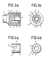
- the drive shaft has a holding head at the end facing away from the drive machine with a recess formed on the end face therein, in which the ends of the individual wire brackets with the aid of a simple self-locking plug-like Clamping element are held.
- the broom to be manufactured thus consists of only three different parts, namely the wire bracket, which can basically be used in any number and shape, the drive shaft, with the molded-on holding head designed as a mounting body and finally the plug-shaped clamping element, which is designed as a clip part.
- the wire bracket Since the wire bracket is anchored in the longitudinal grooves formed in the inner wall of the holding head and thus directly on part of the drive shaft, the torque of the drive is transmitted directly to the wire bracket - ie, avoiding any adhesive or welded connections.
- said longitudinal grooves are supplemented by radial grooves which are also molded into the holding head and into which rectangular extensions of the wire bracket ends are pressed by means of the plug-shaped clamping element.
- the wire brackets are not only secured against forces acting in the axial direction, but also against rotational forces which could cause the wire brackets to twist in themselves.
- the recess in the holding head and, accordingly, the plug-shaped clamping element are preferably cylindrical (claim 3).
- the self-clamping fixation of the clamping element in the holding head and thus the securing of the wire bracket even under the heaviest loads is advantageously achieved in that an annular groove is formed in the wall of the recess, into which an annular bead formed on the clamping element engages.
- the recess can also have an annular bead and the clamping element can have an annular groove (claim 4).
- the whisk and beater according to the invention with wire brackets, all of which have the same shape and size and which are fixed with their two ends in diametrical grooves in the holding head (claim 5). Since the end sections of the wire bracket, in particular in this embodiment due to the crossover of their central parts, extend into the recess of the holding head to a different extent, the bottom of the recess and, accordingly, the end face of the clamping element protruding into the recess are preferably stepped in two spiral steps such that two each diametrical steps are aligned with each other at the same axial height, the radial grooves being formed in the steps of the depression and the step height corresponding approximately to the wire thickness of the wire bracket (claim 6). As a result, the wire brackets are positioned in an axially stepped manner and firmly clamped.
- the inventive design of the proposed beater and whisk simplifies its assembly into one Simple plug and clip process that can be easily carried out by a machine.
- the speed of the final production is therefore completely independent of the specific cycle times of the injection molding machines used for the production of individual parts and is not delayed by adhesive, welding or screwing measures.
- the whisk and whisk according to the invention has a drive shaft 2 with an integrally formed holding head 2 'and a number of wire clips 1 fastened in this holding head 2'.
- the wire clips 1 have, as can be seen from FIG. 2, axially parallel end sections 13 and 13 ', which preferably end in approximately rectangular extensions 14 and 14'.
- the holding head 2 'contains a number of diametrical longitudinal groove pairs 5, 5' corresponding to the number of wire brackets provided for receiving the wire bracket end sections 13, 13 'and radial groove pairs 6, 6' for receiving the right-angled extensions 14 and 14 ' the wire bracket end sections.
- the radial pairs of grooves 6, 6 ' are staggered in the axial direction in such a way that they lie on the steps 11, 11' of two spiral staircases which each fill half the circumference, so that the crossover of the central sections of the wire brackets in the end region of the stirring and whisk according to the invention also then becomes possible when the wire brackets are all the same shape and size. Accordingly, the end face of the clamping element 3 protruding into the recess 4 of the holding head 2 'is staggered so that when the clamping element 3 is inserted into the recess 4 of the holding head 2', a step 12, 12 'at each step 11, 11' of the holding head. of the clamping element comes to rest.
- the recess has a circumferential annular groove 7 and the clamping element has a corresponding annular bead 8.
- a concentrically arranged guide pin 9 is provided in the opening 4 as an assembly aid, to which a matching recess 10 is assigned in the clamping element 3.
Landscapes
- Engineering & Computer Science (AREA)
- Mechanical Engineering (AREA)
- Food Science & Technology (AREA)
- Food-Manufacturing Devices (AREA)
- Mutual Connection Of Rods And Tubes (AREA)
Applications Claiming Priority (2)
| Application Number | Priority Date | Filing Date | Title |
|---|---|---|---|
| DE3533834 | 1985-09-23 | ||
| DE19853533834 DE3533834A1 (de) | 1985-09-23 | 1985-09-23 | Ruehr- und schlagbesen |
Publications (3)
| Publication Number | Publication Date |
|---|---|
| EP0216234A2 true EP0216234A2 (fr) | 1987-04-01 |
| EP0216234A3 EP0216234A3 (en) | 1987-10-28 |
| EP0216234B1 EP0216234B1 (fr) | 1990-04-04 |
Family
ID=6281670
Family Applications (1)
| Application Number | Title | Priority Date | Filing Date |
|---|---|---|---|
| EP86112392A Expired - Lifetime EP0216234B1 (fr) | 1985-09-23 | 1986-09-08 | Fouet mélangeur-batteur |
Country Status (4)
| Country | Link |
|---|---|
| US (1) | US4730939A (fr) |
| EP (1) | EP0216234B1 (fr) |
| CA (1) | CA1270813A (fr) |
| DE (2) | DE3533834A1 (fr) |
Cited By (5)
| Publication number | Priority date | Publication date | Assignee | Title |
|---|---|---|---|---|
| EP0678269A1 (fr) * | 1994-04-23 | 1995-10-25 | Braun Aktiengesellschaft | Batteur-mélangeur |
| FR2720619A1 (fr) * | 1994-06-07 | 1995-12-08 | Combrichon Ets | Manche de fouet de cuisine. |
| GB2326354A (en) * | 1997-05-29 | 1998-12-23 | Kenwood Marks Ltd | A whisk for domestic food mixers |
| US6273602B1 (en) * | 2001-01-08 | 2001-08-14 | Quadra, Inc. | Culinary whisk with coated wires and handle |
| WO2011058234A1 (fr) * | 2009-11-12 | 2011-05-19 | Seb S.A. | Fouet pour appareil de préparation culinaire et appareil muni d'un tel fouet |
Families Citing this family (4)
| Publication number | Priority date | Publication date | Assignee | Title |
|---|---|---|---|---|
| GB2423486B (en) * | 2005-02-23 | 2009-12-09 | Maxpat Trading & Marketing | Culinary whisk |
| JP5497960B1 (ja) * | 2013-04-24 | 2014-05-21 | 中井機械工業株式会社 | 食材用ホイッパー |
| JP5873857B2 (ja) * | 2013-08-21 | 2016-03-01 | 中井機械工業株式会社 | 竪型二軸式の食材ミキサー |
| DE102023134993A1 (de) | 2023-12-13 | 2025-06-18 | De'longhi Braun Household Gmbh | Verfahren zur Herstellung von Arbeitsmitteln für Lebensmittel und Arbeitsmittel zur Verarbeitung von Lebensmitteln |
Family Cites Families (15)
| Publication number | Priority date | Publication date | Assignee | Title |
|---|---|---|---|---|
| DE509734C (de) * | 1930-10-11 | Hugo August Wetzel | Schlagrute mit axial verlaufenden Rillen auf einem der beiden kegelfoermigen Klemmteile fuer die Drahtschleifen | |
| DE61389C (de) * | RODRIGUEZ & Co. in Madrid | Numerir-Rollstempel | ||
| US871247A (en) * | 1905-10-28 | 1907-11-19 | Walter H Tomlinson | Egg-beater. |
| US884085A (en) * | 1907-07-03 | 1908-04-07 | Felix Genge | Egg-whip. |
| AT61398B (de) * | 1912-05-08 | 1913-09-25 | Oberle Fa Geb | Schaumschläger. |
| US1287741A (en) * | 1918-02-15 | 1918-12-17 | Bryan D Pinkney | Beater for mixing-machines. |
| FR562532A (fr) * | 1923-02-21 | 1923-11-12 | Letang Fils | Perfectionnements aux appareils à fouetter les crèmes ou les liquides |
| DE467024C (de) * | 1925-05-10 | 1928-10-17 | Hugo August Wetzel | Schlagrute |
| US1785563A (en) * | 1928-07-27 | 1930-12-16 | Day J H Co | Egg whip and the like |
| FR37672E (fr) * | 1929-12-04 | 1931-01-14 | Fouets démontables pour patissiers | |
| FR930707A (fr) * | 1946-07-17 | 1948-02-03 | Procédé de montage des fouets pour préparations culinaires ou patissières | |
| DE942861C (de) * | 1953-09-18 | 1956-05-09 | Julius Seifert | Schlagbesen fuer Ruehr- und Schlagmaschine mit zwei konzentrischen Spannkoerpern und dazwischen einklemmbarem Gummiring zur Aufnahme der Drahtbuegel-Enden |
| CH423146A (de) * | 1964-08-20 | 1966-10-31 | Lanz & Gehri Mechanische Werks | Schwingbesen |
| DE1806257A1 (de) * | 1968-10-31 | 1970-05-21 | Telefunken Patent | Gedrucktes elektrisches Bauteil,insbesondere Schichtwiderstand |
| DE2423910A1 (de) * | 1974-05-16 | 1975-11-27 | Hans Raeuchle | Ruehrbesen |
-
1985
- 1985-09-23 DE DE19853533834 patent/DE3533834A1/de not_active Withdrawn
-
1986
- 1986-09-08 EP EP86112392A patent/EP0216234B1/fr not_active Expired - Lifetime
- 1986-09-08 DE DE8686112392T patent/DE3669988D1/de not_active Expired - Fee Related
- 1986-09-19 US US06/909,780 patent/US4730939A/en not_active Expired - Fee Related
- 1986-09-19 CA CA000518630A patent/CA1270813A/fr not_active Expired - Fee Related
Cited By (9)
| Publication number | Priority date | Publication date | Assignee | Title |
|---|---|---|---|---|
| EP0678269A1 (fr) * | 1994-04-23 | 1995-10-25 | Braun Aktiengesellschaft | Batteur-mélangeur |
| US5590962A (en) * | 1994-04-23 | 1997-01-07 | Braun Aktiengesellschaft | Rotating beater |
| FR2720619A1 (fr) * | 1994-06-07 | 1995-12-08 | Combrichon Ets | Manche de fouet de cuisine. |
| EP0686369A1 (fr) * | 1994-06-07 | 1995-12-13 | Societe Des Etablissements Combrichon | Manche de fouet de cuisine |
| US5688045A (en) * | 1994-06-07 | 1997-11-18 | Societe Des Etablissements Combrichon | Whisk handle with molded plastic coating |
| GB2326354A (en) * | 1997-05-29 | 1998-12-23 | Kenwood Marks Ltd | A whisk for domestic food mixers |
| US6273602B1 (en) * | 2001-01-08 | 2001-08-14 | Quadra, Inc. | Culinary whisk with coated wires and handle |
| WO2011058234A1 (fr) * | 2009-11-12 | 2011-05-19 | Seb S.A. | Fouet pour appareil de préparation culinaire et appareil muni d'un tel fouet |
| CN102595989A (zh) * | 2009-11-12 | 2012-07-18 | Seb公司 | 用于烹饪制备设备的食物搅拌器和配备有该食物搅拌器的设备 |
Also Published As
| Publication number | Publication date |
|---|---|
| DE3533834A1 (de) | 1987-04-02 |
| EP0216234A3 (en) | 1987-10-28 |
| EP0216234B1 (fr) | 1990-04-04 |
| US4730939A (en) | 1988-03-15 |
| CA1270813A (fr) | 1990-06-26 |
| DE3669988D1 (de) | 1990-05-10 |
Similar Documents
| Publication | Publication Date | Title |
|---|---|---|
| DE68902803T2 (de) | Befestigungselemente mit schraubgewinde. | |
| DE19821234B4 (de) | Verfahren und Vorrichtung zum elektrischen Anschluss einer in einem Sicherungsgehäuse montierten Schmelzsicherung mit einem externen elektrischen Draht | |
| DE10003305C1 (de) | Sitzverstellvorrichtung für Kraftfahrzeuge mit einem Spindelantrieb | |
| EP0353468A1 (fr) | Elément de connexion | |
| EP0216234A2 (fr) | Fouet mélangeur-batteur | |
| DD300226A5 (de) | Lötwerkzeug | |
| DE69202010T2 (de) | Ausgangsklemmenanordnung für einen Wechselstromgenerator in einem Fahrzeug. | |
| DE2736932B2 (de) | Halterung für Stator-Wickelköpfe elektrischer Maschinen | |
| DE4401847A1 (de) | Käfig zur Halterung von Dauermagneten in einem Stator einer elektrischen Maschine | |
| EP0902524B1 (fr) | Moteur à courant continu | |
| DE102009033472A1 (de) | Baugruppe eines Kraftfahrzeugs mit einem Trägerelement und einem daran angeordneten Gehäuseteil | |
| DE10258036B4 (de) | Elektromotor, insbesondere für eine Scheibenwischvorrichtung sowie Scheibenwischvorrichtung, insbesondere für ein Kraftfahrzeug | |
| DE3610340C2 (de) | Anordnung zum Verbinden der Wicklungsdrahtenden einer Statorwicklung eines Elektromotors mit Leitern eines Anschlußkabels | |
| DE19627335C1 (de) | Steckerstift für eine Steckerbrücke | |
| DE3901905C1 (en) | Device on the commutator of an electrical machine | |
| EP0307629A1 (fr) | Plaque de cuisson électrique | |
| CH683012A5 (de) | Befestigungseinrichtung zwischen Tellerbesen und drehbarem Triebkopf einer Strassenkehrmaschine. | |
| DE202020100198U1 (de) | Möbelteilverbindungsanordnung und Einsatzteil dafür | |
| DE19960585A1 (de) | Heizvorrichtung mit unterteiltem Mantelrohr | |
| EP1797332A1 (fr) | Dispositif et procede de fixation d'un rouet sur un arbre | |
| DE4129219C2 (de) | Lampengehäuse für eine Kompaktleuchtstoffröhre | |
| DE1404735C (de) | Schlagbesen mit Schlagdrahten | |
| DE2656734A1 (de) | Baueinheit, insbesondere wischermotor | |
| WO2005032767A1 (fr) | Tournevis | |
| DE3843393A1 (de) | Stirnkollektor fuer eine elektrische maschine |
Legal Events
| Date | Code | Title | Description |
|---|---|---|---|
| PUAI | Public reference made under article 153(3) epc to a published international application that has entered the european phase |
Free format text: ORIGINAL CODE: 0009012 |
|
| AK | Designated contracting states |
Kind code of ref document: A2 Designated state(s): BE DE FR GB IT NL SE |
|
| PUAL | Search report despatched |
Free format text: ORIGINAL CODE: 0009013 |
|
| AK | Designated contracting states |
Kind code of ref document: A3 Designated state(s): BE DE FR GB IT NL SE |
|
| 17P | Request for examination filed |
Effective date: 19871116 |
|
| 17Q | First examination report despatched |
Effective date: 19881031 |
|
| ITF | It: translation for a ep patent filed | ||
| GRAA | (expected) grant |
Free format text: ORIGINAL CODE: 0009210 |
|
| AK | Designated contracting states |
Kind code of ref document: B1 Designated state(s): BE DE FR GB IT NL SE |
|
| GBT | Gb: translation of ep patent filed (gb section 77(6)(a)/1977) | ||
| REF | Corresponds to: |
Ref document number: 3669988 Country of ref document: DE Date of ref document: 19900510 |
|
| ET | Fr: translation filed | ||
| PLBI | Opposition filed |
Free format text: ORIGINAL CODE: 0009260 |
|
| 26 | Opposition filed |
Opponent name: BOSCH-SIEMENS HAUSGERAETE GMBH, MUENCHEN Effective date: 19910104 |
|
| NLR1 | Nl: opposition has been filed with the epo |
Opponent name: BOSCH-SIEMENS HAUSGERATE GMBH. |
|
| ITTA | It: last paid annual fee | ||
| PLBN | Opposition rejected |
Free format text: ORIGINAL CODE: 0009273 |
|
| STAA | Information on the status of an ep patent application or granted ep patent |
Free format text: STATUS: OPPOSITION REJECTED |
|
| 27O | Opposition rejected |
Effective date: 19920102 |
|
| NLR2 | Nl: decision of opposition | ||
| PGFP | Annual fee paid to national office [announced via postgrant information from national office to epo] |
Ref country code: SE Payment date: 19920911 Year of fee payment: 7 |
|
| PGFP | Annual fee paid to national office [announced via postgrant information from national office to epo] |
Ref country code: BE Payment date: 19920917 Year of fee payment: 7 |
|
| PG25 | Lapsed in a contracting state [announced via postgrant information from national office to epo] |
Ref country code: SE Effective date: 19930909 |
|
| PG25 | Lapsed in a contracting state [announced via postgrant information from national office to epo] |
Ref country code: BE Effective date: 19930930 |
|
| BERE | Be: lapsed |
Owner name: BRAUN A.G. Effective date: 19930930 |
|
| EUG | Se: european patent has lapsed |
Ref document number: 86112392.5 Effective date: 19940410 |
|
| PGFP | Annual fee paid to national office [announced via postgrant information from national office to epo] |
Ref country code: NL Payment date: 19990921 Year of fee payment: 14 |
|
| REG | Reference to a national code |
Ref country code: FR Ref legal event code: CD Ref country code: FR Ref legal event code: CA |
|
| PGFP | Annual fee paid to national office [announced via postgrant information from national office to epo] |
Ref country code: GB Payment date: 20000821 Year of fee payment: 15 |
|
| PGFP | Annual fee paid to national office [announced via postgrant information from national office to epo] |
Ref country code: FR Payment date: 20000918 Year of fee payment: 15 |
|
| PG25 | Lapsed in a contracting state [announced via postgrant information from national office to epo] |
Ref country code: NL Free format text: LAPSE BECAUSE OF NON-PAYMENT OF DUE FEES Effective date: 20010401 |
|
| NLV4 | Nl: lapsed or anulled due to non-payment of the annual fee |
Effective date: 20010401 |
|
| PGFP | Annual fee paid to national office [announced via postgrant information from national office to epo] |
Ref country code: DE Payment date: 20010907 Year of fee payment: 16 |
|
| PG25 | Lapsed in a contracting state [announced via postgrant information from national office to epo] |
Ref country code: GB Free format text: LAPSE BECAUSE OF NON-PAYMENT OF DUE FEES Effective date: 20010908 |
|
| GBPC | Gb: european patent ceased through non-payment of renewal fee |
Effective date: 20010908 |
|
| PG25 | Lapsed in a contracting state [announced via postgrant information from national office to epo] |
Ref country code: FR Free format text: LAPSE BECAUSE OF NON-PAYMENT OF DUE FEES Effective date: 20020531 |
|
| REG | Reference to a national code |
Ref country code: FR Ref legal event code: ST |
|
| PG25 | Lapsed in a contracting state [announced via postgrant information from national office to epo] |
Ref country code: DE Free format text: LAPSE BECAUSE OF NON-PAYMENT OF DUE FEES Effective date: 20030401 |
|
| PG25 | Lapsed in a contracting state [announced via postgrant information from national office to epo] |
Ref country code: IT Free format text: LAPSE BECAUSE OF NON-PAYMENT OF DUE FEES;WARNING: LAPSES OF ITALIAN PATENTS WITH EFFECTIVE DATE BEFORE 2007 MAY HAVE OCCURRED AT ANY TIME BEFORE 2007. THE CORRECT EFFECTIVE DATE MAY BE DIFFERENT FROM THE ONE RECORDED. Effective date: 20050908 |