EP0216512B1 - Emballages multiples et dispositifs porteurs, machines et procédés pour leur fabrication - Google Patents
Emballages multiples et dispositifs porteurs, machines et procédés pour leur fabrication Download PDFInfo
- Publication number
- EP0216512B1 EP0216512B1 EP86306505A EP86306505A EP0216512B1 EP 0216512 B1 EP0216512 B1 EP 0216512B1 EP 86306505 A EP86306505 A EP 86306505A EP 86306505 A EP86306505 A EP 86306505A EP 0216512 B1 EP0216512 B1 EP 0216512B1
- Authority
- EP
- European Patent Office
- Prior art keywords
- apertures
- carrier
- containers
- carrier device
- pitch
- Prior art date
- Legal status (The legal status is an assumption and is not a legal conclusion. Google has not performed a legal analysis and makes no representation as to the accuracy of the status listed.)
- Expired
Links
Images
Classifications
-
- B—PERFORMING OPERATIONS; TRANSPORTING
- B65—CONVEYING; PACKING; STORING; HANDLING THIN OR FILAMENTARY MATERIAL
- B65B—MACHINES, APPARATUS OR DEVICES FOR, OR METHODS OF, PACKAGING ARTICLES OR MATERIALS; UNPACKING
- B65B15/00—Attaching articles to cards, sheets, strings, webs, or other carriers
-
- B—PERFORMING OPERATIONS; TRANSPORTING
- B65—CONVEYING; PACKING; STORING; HANDLING THIN OR FILAMENTARY MATERIAL
- B65D—CONTAINERS FOR STORAGE OR TRANSPORT OF ARTICLES OR MATERIALS, e.g. BAGS, BARRELS, BOTTLES, BOXES, CANS, CARTONS, CRATES, DRUMS, JARS, TANKS, HOPPERS, FORWARDING CONTAINERS; ACCESSORIES, CLOSURES, OR FITTINGS THEREFOR; PACKAGING ELEMENTS; PACKAGES
- B65D71/00—Bundles of articles held together by packaging elements for convenience of storage or transport, e.g. portable segregating carrier for plural receptacles such as beer cans or pop bottles; Bales of material
- B65D71/50—Bundles of articles held together by packaging elements for convenience of storage or transport, e.g. portable segregating carrier for plural receptacles such as beer cans or pop bottles; Bales of material comprising a plurality of articles held together only partially by packaging elements formed otherwise than by folding a blank
- B65D71/504—Bundles of articles held together by packaging elements for convenience of storage or transport, e.g. portable segregating carrier for plural receptacles such as beer cans or pop bottles; Bales of material comprising a plurality of articles held together only partially by packaging elements formed otherwise than by folding a blank the element being formed from a flexible sheet provided with slits or apertures intended to be stretched over the articles and adapt to the shape of the article
Definitions
- This invention relates to plastics carrier devices for forming packages for a plurality of containers. More specifically, the invention relates to a multi-packaging device, strip-stock for producing such a multi-packaging device, methods of producing the device and methods and machinery for applying a carrier device to containers.
- Multi-packaging devices configured from plastics material strips of integrally connected, resilient bands have become commonplace for the formation of packages of arrays of containers.
- Various machines and methods have also been developed for application of the strips in a high speed production line basis.
- Packaging devices of the type referred to above began with the early developments described in US-A-2 874 835 and have been continually improved up to and including the devices shown in US-A-4 219 117.
- machinery and method for applying the carriers have been described in US-A-3 032 943, US-A-3 032 944, US-A-3 383 828 and US-A-4 250 687.
- Present commercial versions of such multi-packaging systems which include the devices, machinery and methods, incorporate the latest of each of the above noted patents.
- a typical carrier device of thermoplastic material for an array of containers having a particular peripheral dimension includes a corresponding array of apertures formed by interconnected bands, the apertures being elongate in the longitudinal direction of the device and having an unstressed peripheral dimension substantially less than said particular peripheral dimension.
- such a carrier device is formed to have a plurality of transversely directed corrugated sections to enable the device to be elongated by tensioning and thereby enlarge the peripheral dimension of the apertures to allow them to be associated with a container to be multi-packaged.
- a package consists of a carrier in accordance with the one aspect of this invention and a plurality of cylindrical containers arranged in an array, the containers having circumferential surface portions of the particular peripheral dimension immediately below an upper chime, a container being located in each aperture with each of the bands encircling one of the containers immediately below its chime and resiliently tensioned about it.
- a method of making multi-packages includes the steps of:
- the invention further relates to a method of multi-packaging containers according to claim 14 and to a machine for multi-packaging according to claim 16.
- the multi-packaging device of the present invention includes resilient, elastic, plastics bands which have a cross-sectional configuration that includes a series of relatively closely spaced ribs, which are interconnected by short struts of elongated plastic material.
- the combination of ribs and struts, in the composite create corrugated sections.
- This configuration in comparison with the prior art cross-sectional configuration of a thin, flat sheet of material, provides material content and performance advantages.
- each band includes a plurality of alternating, thin discrete sections, that have been prestretched and oriented, and thicker rib sections.
- the alternating sections are arranged to be generally lengthwise of the container and the rib sections act to maintain the necessary stiffness of the carrier device in the length direction of the containers while permitting less material and sufficient flexure and tensioning to remain in the radial direction about the container.
- the package may include means to facilitate grasping with a finger gripping aperture formed between each group of four containers.
- the carrier device of the present invention is capable of being manufactured with appreciably less material than prior art devices as a result of the corrugated sections of ribs and struts.
- the selective elongation of the discrete strut portions increases the "effective" material content of the device.
- the corrugation of the strip may be accomplished by feeding a strip of a preformed material through a nip formed between meshing rolls of gear-like reconfiguring devices. Each tooth of the mating gear device is designed to register in a root area in the associated mating gear.
- the crests of the teeth of alternating mating gears each capture a segment of the preformed sheet and together stretch the segment between the two captured segments to an extent sufficient to "work” or elongate the segment, beyond its elastic limit to axially orient it, while the captured segments are unstretched and thus retain their elasticity.
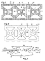
- the device 10 generally resembles prior art carrier devices such as shown in U.S. patent 4 219 117, in that it includes a series of D-shaped apertures 12 arranged in a plurality of ranks and rows which are created by bands 14 interconnected by webs 16 and 18.
- the preferred embodiment of the carrier device is shown to have two rows of three ranks to create a six-pack.
- the bands 14, again similar to the prior art carrier noted above, are con figured to include relatively straight outer section band 21 and a U or V-shaped inner band section 22.
- the preferred embodiment also shows the lateral webs means 18 to be created by a plurality of longitudinally spaced straps including a pair of outer straps 15 and central strap means 17.
- An enlarged finger hole 20, in a preferred embodiment is shown as being positioned between web means 18.
- the outer band 21 may also be slightly undulating at its outer edges, providing slightly bulged regions 27 at the juncture of the outer and inner band to further strengthen the band when stretched during application.
- the preform device 100 shown in Fig. 2 which creates the final product in Fig. 1 is significantly shorter and narrower than a typical prior art carrier for a similar container size.
- a representative comparison will reveal typical prior art carriers to be approximately 8-1/2" X 5-1/2" (216 x 140 mm) while a preform according to this invention for a similar application will be approximately 4" X 2-1/2" (182 x 64 mm) this type of comparison will indicate that substantially less material is required to create a carrier device than as typified in the prior art.
- the preform 100 may be manufactured by essentially the same process that is utilized in manufacturing the prior art carrier shown in U.S. 4 219 117, i.e., punching predesigned apertures in an endless strip of polyethylene or similar resilient thermoplastic material.
- the preform 100 is substantially identical in all respects except length and cross-sectional configuration to the finished carrier device 10 and therefore like elements are identified with like numerals with the addition of prefix 1 in description of the preform.
- Device 10 will include a plurality or series of closely spaced corrugations 24 extending laterally across the device.
- the cross-sectional configuration of device 10 and corrugations 24 can be seen at the right most extremity of Fig. 3.
- the corrugations are essentially alternating thick rib sections 25 and thin strut sections 26.
- "one" corrugation is defined as one complete “pitch" of the series of alternating ribs and struts as shown as “P" in Fig. 3.
- the corrugations are created continuously by feeding the strip of preforms 100 into a set of meshing gear-like rollers 28 and 30 in directions of movement as shown in Fig. 3.
- the gears will include a series of teeth 29 and root sections 32 alternating at a given pitch. Teeth 29 will also be defined as including a crest section 31 and flank sections 33.
- the exact dimensions and gear parameters will of course be determined by the speed of production, thickness of material and thickness of rib and strut sections desired.
- the rib sections 25 will essentially remain the thickness of the preform strip, as these discrete sections are grasped by the crest 31 of one of the teeth of a gear and the root 32 of the corresponding gear. As that combination of crest and root with the discrete section therebetween become completely meshed, the regions 26 between adjacent ribs 25 are stretched, elongated, and/or compressed and become significantly thinner and molecularly oriented.
- the thickness of the stock and gear component dimensions and parameters are designed so that the sections 26 do not return to their initial thickness and thus are permanently oriented, thinned and elongated.
- the gear meshing operation creates a wave-like pattern in cross-section for the finished device 10.
- the wave-like pattern will provide an alternating series of ribs extending above and below a central cross-sectional plane of the device.
- This alternating, wave-like configuration creates a device which can be elongated by applying predetermined lengthwise tension on the strip or device sufficient to relocate the relative elevations of the rib sections 25 to be essentially co-planar.
- the effective length of the device may he increased without significantly stretching the material that still has stretch capabilities, i.e., the ribs 25. Since the device 10 does have "memory" or a desire to return to the shortened configuration shown in Fig. 3, there is a certain amount of static reactive tension built into the device when elongated as just described.
- the carrier device 10 in its at rest or non- elongated state is also appreciable smaller than a prior art carrier.
- a typical carrier device, in relaxed state, will be approximately 7" 2-1/2" (178 x 64 mm) compare to the prior art dimensions previously noted.
- the carrier device 10 of the instant invention is appreciatively smaller than the prior art devices, it follows that device 10 must be subjected to significantly greater stretching forces than the prior art.
- the carrier device 10 or series of interconnected devices are designed to be an integral part of a system for creating multi-packages in a manner similar to the systems referred to in the background of the invention.
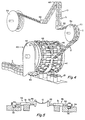
- the preferred applicating apparatus 40 for this system is shown in Figs. 4 and 6 and can be described as basically including; a drum-like member 42, designed to rotate about an axis which is located above conveyor feeding a series of continuous moving containers 11 through a star wheel locating means 44 to create a series of multi-packages 13.
- the drum 42 will include a circumferentially arranged series of equally spaced pairs of opposing jaw assemblies 46.
- Each jaw assembly includes a jaw member 48 which faces a similar jaw in the opposing assembly across an open "throat" region 47 of the drum.
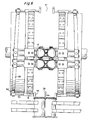
- Jaws 48 are connected by rods to a cam follower 54 which engages a cam track means 52 on either side of the throat region.
- the rods are supported by fixed bearing block means 51.
- the machine described in the prior art patent 4 250 682 incorporates a drum which includes jaw assemblies that have a moving portion and a stationary portion; while the instant invention incorporates a jaw assembly with both jaw portions designed to move relative to the center line of movement of containers. Since the device of Fig. 1 is designed to be more highly stretched than any prior art device, it requires an equal distribution of the stretching forces created by the jaw mechanism, thus the departure from the rather simple teachings of the 4 250 682 patent while retaining the "open throat" or totally cantilevered jaw mechanism techniques.
- a reel 64 of the carriers which create a succession of devices 10 is positioned to be above and preferably on the entry side of the drum 42 and fed through a series of idler or guiding rollers 62 into a tensioning wheel 58.
- This tensioning wheel includes a circumferentially spaced series of cogs 60, each cog designed to interfit within each aperture 12 in the device 10. It is important to note that prior to being received on the tensioning wheel, the strip of devices resemblies the cross-sectional configuration as shown in Fig. 3, i.e., it has not been tensioned longitudinally.
- the strip is tensioned to elongate and increase the pitch or the distance between ranks of apertures.
- This tensioning which occurs between the existing cog on the wheel 58 and the entry jaw assembly 46 is not appreciably stretching the thermoplastic material but essentially bringing the rib sections 15 to a co-planar position as compared to the stepped position of Fig. 3.
- the pitch or distance between jaws 48 and distance between cans of a package is designed to be 72.4 mm (2.85 inches) while the pitch distance of aperture 12 of the untensioned carrier device and the cogs 60 is 55.6 mm (2.19 inches).
- This surface speed differential can be accomplished in a number of ways, for example, the preferred manner is to develop a tensioning wheel with a diameter less than that of the diameter of the drum and rotate the tensioning wheel and drum at the same rotational speed by driving them off the same mechanism thus creating a surface speed of the jaws greater than the surface speed of the cogs.
- FIG. 6 A more detailed showing of the application drum 42 is shown in partial assembly Fig. 6 with the cams 52, cam followers 54, jaws 48 and pretensioned carrier 10 in a practically totally laterally stretched arrangement.
- the carrier device is stripped from the jaws through the use of a stripping plate 56 as the can tops are inserted through the laterally stretched apertures.
- the continuous strip and the continuous stream of containers are separated into their desired array, for example a six-pack 13.
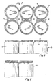
- Figs. 7, 8 and 9 show that the rib-like or corrugated structure described in detail relative to the device of Fig. 1, creates a closely spaced series of ribs 24 which act as struts abutting against the rims 1 of the cans, thus serving to essentially stiffen the package while minimizing the material content.
- the struts or thick rib sections 25 are regions which have a stretch capability remaining in them while the thin, oriented, sections 26, have essentially no stretch remaining in them. These thinned oriented sections 26, however support and compliment the strut-like configuration of the bands. It has been found that a package 13 created using the device 10 can be manufactured with approximately 25 % less material than the prior art device of U.S. patent 4 119 117 while retaining the cans under jolting conditions as well as not better than the prior art device.
- a preferred embodiment of the device 10 and package 13 will have a density of corrugations 24 which is approximately 40 to 50 per inch (1.6 to 2 per mm). This density creates an appropriate number of ribs and individually stretchable thick sections 25 about the periphery of the band and can.
- the bands creating the dimension of the apertures 12 can be significantly increased in diameter e.g., in the range of 2 to 1 from the original diameter. This will become apparent in comparing the apertures shown in Fig. 1 to the dimension of the diameters of the cans associated with the device shown in Fig. 7. This comparison clearly illustrates one of the important features of the invention i.e., ability to use far less material, reconfigure the device by stretching significantly and still create a usuable, functional package.
- a unique and clearly advantageous multi-packaging system is created by this invention.
- a carrier device which is capable of utilizing significantly less material than prior art devices, capable of being stretched significantly greater amounts without failure, capable of creating a package which is equal to or superior to the prior art devices which utilize more material, capable of being incorporated into a multi-packaging system which utilizes very highspeed applicating machines that cooperate and compliment the carrier design.
Landscapes
- Mechanical Engineering (AREA)
- Engineering & Computer Science (AREA)
- Packages (AREA)
- Auxiliary Devices For And Details Of Packaging Control (AREA)
- Polyesters Or Polycarbonates (AREA)
- Heterocyclic Carbon Compounds Containing A Hetero Ring Having Oxygen Or Sulfur (AREA)
- Wrapping Of Specific Fragile Articles (AREA)
- Container Filling Or Packaging Operations (AREA)
- Supplying Of Containers To The Packaging Station (AREA)
- Apparatus Associated With Microorganisms And Enzymes (AREA)
- Separation By Low-Temperature Treatments (AREA)
- Package Frames And Binding Bands (AREA)
- External Artificial Organs (AREA)
Claims (17)
Priority Applications (1)
| Application Number | Priority Date | Filing Date | Title |
|---|---|---|---|
| AT86306505T ATE46299T1 (de) | 1985-08-23 | 1986-08-21 | Mehrfachpackungen und traegervorrichtungen, maschinen und verfahren zu deren herstellung. |
Applications Claiming Priority (2)
| Application Number | Priority Date | Filing Date | Title |
|---|---|---|---|
| US768587 | 1985-08-23 | ||
| US06/768,587 US4624363A (en) | 1985-08-23 | 1985-08-23 | Multi-packaging devices, methods and machines |
Publications (2)
| Publication Number | Publication Date |
|---|---|
| EP0216512A1 EP0216512A1 (fr) | 1987-04-01 |
| EP0216512B1 true EP0216512B1 (fr) | 1989-09-13 |
Family
ID=25082906
Family Applications (1)
| Application Number | Title | Priority Date | Filing Date |
|---|---|---|---|
| EP86306505A Expired EP0216512B1 (fr) | 1985-08-23 | 1986-08-21 | Emballages multiples et dispositifs porteurs, machines et procédés pour leur fabrication |
Country Status (14)
| Country | Link |
|---|---|
| US (1) | US4624363A (fr) |
| EP (1) | EP0216512B1 (fr) |
| JP (1) | JPS6252014A (fr) |
| KR (1) | KR870002000A (fr) |
| CN (1) | CN1010669B (fr) |
| AT (1) | ATE46299T1 (fr) |
| AU (1) | AU588046B2 (fr) |
| CA (1) | CA1286259C (fr) |
| DE (1) | DE3665557D1 (fr) |
| DK (1) | DK402486A (fr) |
| ES (1) | ES2002273A6 (fr) |
| HK (1) | HK99390A (fr) |
| NZ (1) | NZ217236A (fr) |
| SG (1) | SG79790G (fr) |
Families Citing this family (13)
| Publication number | Priority date | Publication date | Assignee | Title |
|---|---|---|---|---|
| US5038928A (en) * | 1990-05-07 | 1991-08-13 | Illinois Tool Works Inc. | Carrier stock with integral handles |
| US5154295A (en) * | 1990-11-13 | 1992-10-13 | Stoner Theodore A | Interlocking container structures |
| JPH09501889A (ja) * | 1992-06-02 | 1997-02-25 | ミネソタ マイニング アンド マニュファクチャリング カンパニー | 可変伸張低粘着化粘着テープによる一体化システム |
| US5305877A (en) * | 1993-04-21 | 1994-04-26 | Illinois Tool Works Inc. | Carrier stock with outer band segments having concave edge portions |
| US5456350A (en) * | 1994-08-18 | 1995-10-10 | Illinois Tool Works Inc. | Carrier stock having finger-gripping straps and strut-producing straps |
| US5511656A (en) * | 1994-08-18 | 1996-04-30 | Illinois Tool Works Inc. | Carrier stock having finger-gripping straps curved inwardly toward each other |
| US6122893A (en) * | 1998-12-22 | 2000-09-26 | Illinois Tool Works Inc. | System and apparatus for packaging a uniform group of container having a range of diameters |
| US6964144B1 (en) | 2000-11-16 | 2005-11-15 | Illinois Tool Works Inc. | System and apparatus for packaging containers |
| US20060289315A1 (en) | 2005-03-07 | 2006-12-28 | Robert Olsen | Container carrier |
| GB0920396D0 (en) * | 2009-11-23 | 2010-01-06 | Dijofi Ltd | A plastics container carrier |
| GB201411919D0 (en) * | 2014-07-03 | 2014-08-20 | British Polythene Ltd | A container carrier |
| AU2020266486A1 (en) * | 2019-05-01 | 2021-12-02 | Westrock Packaging Systems, Llc | Article top engaging device, article carrier and blank therefor |
| BE1027706B1 (nl) * | 2019-07-16 | 2021-05-25 | Anheuser Busch Inbev Nv | Driedimensionale drager met aangepaste lippen |
Family Cites Families (11)
| Publication number | Priority date | Publication date | Assignee | Title |
|---|---|---|---|---|
| US3202448A (en) * | 1958-05-22 | 1965-08-24 | Jones & Co Inc R A | Display carrier |
| US3032944A (en) * | 1959-12-24 | 1962-05-08 | Illinois Tool Works | Container and carrier assembling machine |
| US3716963A (en) * | 1970-11-25 | 1973-02-20 | Owens Illinois Inc | Shrink-film capping machine |
| US4153664A (en) * | 1976-07-30 | 1979-05-08 | Sabee Reinhardt N | Process for pattern drawing of webs |
| NO152611C (no) * | 1978-10-16 | 1985-10-23 | Plg Res | Plastnettkonstruksjon, fremgangsmaate til dens fremstilling og anvendelse av konstruksjonen |
| US4219117A (en) * | 1979-04-18 | 1980-08-26 | Illinois Tool Works Inc. | Multipackaging device |
| US4250682A (en) * | 1979-07-19 | 1981-02-17 | Illinois Tool Works Inc. | Wheel assembly for use in an apparatus for multipackaging containers |
| US4356914A (en) * | 1979-12-05 | 1982-11-02 | Illinois Tool Works Inc. | Asymmetric container carrier stock |
| JPS5934561A (ja) * | 1982-08-23 | 1984-02-24 | Canon Inc | 画像形成装置 |
| US4462494A (en) * | 1983-01-24 | 1984-07-31 | Grip-Pak, Inc. | Multi-packaging device for cylindrical containers |
| JPS6010924A (ja) * | 1983-06-30 | 1985-01-21 | Seiko Instr & Electronics Ltd | Fm受信機 |
-
1985
- 1985-08-23 US US06/768,587 patent/US4624363A/en not_active Expired - Lifetime
-
1986
- 1986-08-14 AU AU61178/86A patent/AU588046B2/en not_active Ceased
- 1986-08-14 CA CA000515999A patent/CA1286259C/fr not_active Expired - Fee Related
- 1986-08-18 NZ NZ217236A patent/NZ217236A/xx unknown
- 1986-08-21 AT AT86306505T patent/ATE46299T1/de not_active IP Right Cessation
- 1986-08-21 DE DE8686306505T patent/DE3665557D1/de not_active Expired
- 1986-08-21 EP EP86306505A patent/EP0216512B1/fr not_active Expired
- 1986-08-22 DK DK402486A patent/DK402486A/da not_active Application Discontinuation
- 1986-08-22 ES ES8601288A patent/ES2002273A6/es not_active Expired
- 1986-08-22 KR KR1019860006951A patent/KR870002000A/ko not_active Ceased
- 1986-08-22 JP JP61195695A patent/JPS6252014A/ja active Pending
- 1986-08-23 CN CN86106209A patent/CN1010669B/zh not_active Expired
-
1990
- 1990-09-29 SG SG797/90A patent/SG79790G/en unknown
- 1990-11-29 HK HK993/90A patent/HK99390A/xx unknown
Also Published As
| Publication number | Publication date |
|---|---|
| AU588046B2 (en) | 1989-09-07 |
| CN1010669B (zh) | 1990-12-05 |
| AU6117886A (en) | 1987-02-26 |
| DK402486D0 (da) | 1986-08-22 |
| EP0216512A1 (fr) | 1987-04-01 |
| SG79790G (en) | 1990-11-23 |
| DK402486A (da) | 1987-02-24 |
| CA1286259C (fr) | 1991-07-16 |
| CN86106209A (zh) | 1987-07-29 |
| ATE46299T1 (de) | 1989-09-15 |
| KR870002000A (ko) | 1987-03-28 |
| DE3665557D1 (en) | 1989-10-19 |
| NZ217236A (en) | 1989-01-06 |
| HK99390A (en) | 1990-12-07 |
| ES2002273A6 (es) | 1988-08-01 |
| JPS6252014A (ja) | 1987-03-06 |
| US4624363A (en) | 1986-11-25 |
Similar Documents
| Publication | Publication Date | Title |
|---|---|---|
| EP0216512B1 (fr) | Emballages multiples et dispositifs porteurs, machines et procédés pour leur fabrication | |
| US3959949A (en) | System, machine and method for multipackaging containers | |
| EP0456357B1 (fr) | Dispositif pour appliquer une élément porteur pour plusieurs récipients | |
| US4741729A (en) | Multi-packaging devices, methods and machines | |
| US4121401A (en) | Method and apparatus for applying reinforcing strips to adjacent pairs of containers | |
| IE49953B1 (en) | Wheel assembly for use in an apparatus for multipackaging containers | |
| US4354333A (en) | Packaging apparatus | |
| US3946535A (en) | Carrier applicating machine and method | |
| US3831741A (en) | Extruded plastic container carrier stock and methods for producing the same | |
| FI68026C (fi) | Anordning foer att foerena flera burkar till foerpackningar geom anvaendande av elastiskt plastbaermedel | |
| CA1300482C (fr) | Dispositif d'emballage en groupe de canettes | |
| US3938656A (en) | Container carrier and method of making same | |
| DE2221780B2 (de) | Behälterträger aus blattförmigem, elastischem Kunststoffmaterial | |
| US3968621A (en) | Method of packaging using extruded net | |
| US4121712A (en) | Plastic sheet band multi-packaging device and method of assembling same to containers | |
| EP0004071A2 (fr) | Procédé et appareil pour la fabrication en continu d'un matériau thermoplastique orienté biaxialement et pour former des articles à partir de ce matériau au moyen d'organes de formage coopérant par intermittence avec ce matériau | |
| US3904186A (en) | Accordion, folding and cutting apparatus | |
| US4330058A (en) | Container carrier preform strip | |
| WO1994019163A3 (fr) | Appareil et procede d'irradiation uniforme d'un toron | |
| KR20170035928A (ko) | 로터리 다이 프레스로 컨테이너 캐리어를 제조하기 위한 방법 및 장치 | |
| BR9402687A (pt) | Processo para a produção contínua de caneloni e máquina para sua produção. | |
| US4953342A (en) | Multi package containers | |
| US4301918A (en) | Container carrier preform | |
| EP2969843B1 (fr) | Porteur de récipients | |
| WO2019094947A1 (fr) | Support de finition mate imprimée |
Legal Events
| Date | Code | Title | Description |
|---|---|---|---|
| PUAI | Public reference made under article 153(3) epc to a published international application that has entered the european phase |
Free format text: ORIGINAL CODE: 0009012 |
|
| AK | Designated contracting states |
Kind code of ref document: A1 Designated state(s): AT BE CH DE FR GB IT LI NL SE |
|
| 17P | Request for examination filed |
Effective date: 19870904 |
|
| 17Q | First examination report despatched |
Effective date: 19880509 |
|
| GRAA | (expected) grant |
Free format text: ORIGINAL CODE: 0009210 |
|
| AK | Designated contracting states |
Kind code of ref document: B1 Designated state(s): AT BE CH DE FR GB IT LI NL SE |
|
| REF | Corresponds to: |
Ref document number: 46299 Country of ref document: AT Date of ref document: 19890915 Kind code of ref document: T |
|
| REF | Corresponds to: |
Ref document number: 3665557 Country of ref document: DE Date of ref document: 19891019 |
|
| ITF | It: translation for a ep patent filed | ||
| ET | Fr: translation filed | ||
| PLBE | No opposition filed within time limit |
Free format text: ORIGINAL CODE: 0009261 |
|
| STAA | Information on the status of an ep patent application or granted ep patent |
Free format text: STATUS: NO OPPOSITION FILED WITHIN TIME LIMIT |
|
| 26N | No opposition filed | ||
| PGFP | Annual fee paid to national office [announced via postgrant information from national office to epo] |
Ref country code: FR Payment date: 19910712 Year of fee payment: 6 |
|
| PGFP | Annual fee paid to national office [announced via postgrant information from national office to epo] |
Ref country code: DE Payment date: 19910716 Year of fee payment: 6 Ref country code: CH Payment date: 19910716 Year of fee payment: 6 Ref country code: AT Payment date: 19910716 Year of fee payment: 6 |
|
| PGFP | Annual fee paid to national office [announced via postgrant information from national office to epo] |
Ref country code: SE Payment date: 19910718 Year of fee payment: 6 |
|
| PGFP | Annual fee paid to national office [announced via postgrant information from national office to epo] |
Ref country code: BE Payment date: 19910726 Year of fee payment: 6 |
|
| PGFP | Annual fee paid to national office [announced via postgrant information from national office to epo] |
Ref country code: GB Payment date: 19910731 Year of fee payment: 6 |
|
| ITTA | It: last paid annual fee | ||
| PGFP | Annual fee paid to national office [announced via postgrant information from national office to epo] |
Ref country code: NL Payment date: 19910831 Year of fee payment: 6 |
|
| PG25 | Lapsed in a contracting state [announced via postgrant information from national office to epo] |
Ref country code: GB Effective date: 19920821 Ref country code: AT Effective date: 19920821 |
|
| PG25 | Lapsed in a contracting state [announced via postgrant information from national office to epo] |
Ref country code: SE Effective date: 19920822 |
|
| PG25 | Lapsed in a contracting state [announced via postgrant information from national office to epo] |
Ref country code: LI Effective date: 19920831 Ref country code: CH Effective date: 19920831 Ref country code: BE Effective date: 19920831 |
|
| BERE | Be: lapsed |
Owner name: ILLINOIS TOOL WORKS INC. Effective date: 19920831 |
|
| PG25 | Lapsed in a contracting state [announced via postgrant information from national office to epo] |
Ref country code: NL Effective date: 19930301 |
|
| NLV4 | Nl: lapsed or anulled due to non-payment of the annual fee | ||
| GBPC | Gb: european patent ceased through non-payment of renewal fee |
Effective date: 19920821 |
|
| PG25 | Lapsed in a contracting state [announced via postgrant information from national office to epo] |
Ref country code: FR Effective date: 19930430 |
|
| REG | Reference to a national code |
Ref country code: CH Ref legal event code: PL |
|
| PG25 | Lapsed in a contracting state [announced via postgrant information from national office to epo] |
Ref country code: DE Effective date: 19930501 |
|
| REG | Reference to a national code |
Ref country code: FR Ref legal event code: ST |
|
| EUG | Se: european patent has lapsed |
Ref document number: 86306505.8 Effective date: 19930307 |
|
| PG25 | Lapsed in a contracting state [announced via postgrant information from national office to epo] |
Ref country code: IT Free format text: LAPSE BECAUSE OF NON-PAYMENT OF DUE FEES;WARNING: LAPSES OF ITALIAN PATENTS WITH EFFECTIVE DATE BEFORE 2007 MAY HAVE OCCURRED AT ANY TIME BEFORE 2007. THE CORRECT EFFECTIVE DATE MAY BE DIFFERENT FROM THE ONE RECORDED. Effective date: 20050821 |