EP0456357B1 - Dispositif pour appliquer une élément porteur pour plusieurs récipients - Google Patents
Dispositif pour appliquer une élément porteur pour plusieurs récipients Download PDFInfo
- Publication number
- EP0456357B1 EP0456357B1 EP91303390A EP91303390A EP0456357B1 EP 0456357 B1 EP0456357 B1 EP 0456357B1 EP 91303390 A EP91303390 A EP 91303390A EP 91303390 A EP91303390 A EP 91303390A EP 0456357 B1 EP0456357 B1 EP 0456357B1
- Authority
- EP
- European Patent Office
- Prior art keywords
- articles
- carrier
- travel
- path
- arms
- Prior art date
- Legal status (The legal status is an assumption and is not a legal conclusion. Google has not performed a legal analysis and makes no representation as to the accuracy of the status listed.)
- Expired - Lifetime
Links
- 239000000969 carrier Substances 0.000 claims abstract description 16
- 239000000463 material Substances 0.000 claims description 10
- 230000001360 synchronised effect Effects 0.000 claims description 4
- 230000037431 insertion Effects 0.000 claims 1
- 238000003780 insertion Methods 0.000 claims 1
- 239000012876 carrier material Substances 0.000 description 28
- 230000000717 retained effect Effects 0.000 description 10
- 235000013361 beverage Nutrition 0.000 description 5
- 238000000926 separation method Methods 0.000 description 5
- 238000000605 extraction Methods 0.000 description 3
- 238000000034 method Methods 0.000 description 3
- 238000004806 packaging method and process Methods 0.000 description 3
- 230000000737 periodic effect Effects 0.000 description 3
- 230000000295 complement effect Effects 0.000 description 2
- 239000002131 composite material Substances 0.000 description 2
- 230000014759 maintenance of location Effects 0.000 description 2
- 239000012858 resilient material Substances 0.000 description 2
- 239000004698 Polyethylene Substances 0.000 description 1
- 230000003213 activating effect Effects 0.000 description 1
- 230000001154 acute effect Effects 0.000 description 1
- 238000010276 construction Methods 0.000 description 1
- 238000013480 data collection Methods 0.000 description 1
- 230000007423 decrease Effects 0.000 description 1
- 230000003247 decreasing effect Effects 0.000 description 1
- 230000000694 effects Effects 0.000 description 1
- 230000007246 mechanism Effects 0.000 description 1
- 239000002985 plastic film Substances 0.000 description 1
- -1 polyethylene Polymers 0.000 description 1
- 229920000573 polyethylene Polymers 0.000 description 1
- 230000003313 weakening effect Effects 0.000 description 1
Images


Classifications
-
- B—PERFORMING OPERATIONS; TRANSPORTING
- B65—CONVEYING; PACKING; STORING; HANDLING THIN OR FILAMENTARY MATERIAL
- B65B—MACHINES, APPARATUS OR DEVICES FOR, OR METHODS OF, PACKAGING ARTICLES OR MATERIALS; UNPACKING
- B65B61/00—Auxiliary devices, not otherwise provided for, for operating on sheets, blanks, webs, binding material, containers or packages
- B65B61/04—Auxiliary devices, not otherwise provided for, for operating on sheets, blanks, webs, binding material, containers or packages for severing webs, or for separating joined packages
-
- B—PERFORMING OPERATIONS; TRANSPORTING
- B65—CONVEYING; PACKING; STORING; HANDLING THIN OR FILAMENTARY MATERIAL
- B65B—MACHINES, APPARATUS OR DEVICES FOR, OR METHODS OF, PACKAGING ARTICLES OR MATERIALS; UNPACKING
- B65B3/00—Packaging plastic material, semiliquids, liquids or mixed solids and liquids, in individual containers or receptacles, e.g. bags, sacks, boxes, cartons, cans, or jars
-
- B—PERFORMING OPERATIONS; TRANSPORTING
- B65—CONVEYING; PACKING; STORING; HANDLING THIN OR FILAMENTARY MATERIAL
- B65B—MACHINES, APPARATUS OR DEVICES FOR, OR METHODS OF, PACKAGING ARTICLES OR MATERIALS; UNPACKING
- B65B17/00—Other machines, apparatus, or methods for packaging articles or materials
- B65B17/02—Joining articles, e.g. cans, directly to each other for convenience of storage, transport, or handling
- B65B17/025—Joining articles, e.g. cans, directly to each other for convenience of storage, transport, or handling the articles being joined by a top carrier element
Definitions
- This invention relates generally to the article packaging arts and more particularly to a machine and method for assembling a plurality of articles with a packaging carrier.
- US-A-4,018,331 to Klygis and US-A-4,219,117 to Weaver et al. are two examples of carriers used to package a plurality of articles in close relation.
- this type of carrier is formed of a resilient material which can be deformably stretched. When stretched, openings formed in the material enlarge to permit assembly over the ends of articles. Once the stretching force is removed, the carrier material elastically reforms around the articles.
- these two references show generally cylindrical beverage containers retained within the carrier, articles of other dimensions may be assembled with an appropriately dimensioned carrier strip employing a similar process.
- Weaver et al. shows a carrier strip which comprises two rows of longitudinally adjacent bands.
- the Klygis patent shows a carrier strip which is formed with three rows of longitudinally adjacent bands.
- the strip is engaged along the outside edge of the bands and stretched outwardly so that each band forms an opening which complements the article to be assembled therewith.
- forces exerted on the two outermost bands of each row of three adjacent bands stretch the medial band deforming it to complementarily accommodate an article assembled therethrough.
- An apparatus as shown in US-A-4,250,682 to Braun provides a machine which engages a carrier strip and assembles the carrier strip with a plurality of articles moving in close relation thereto.
- the apparatus in Braun has a rotary drum with carrier stretching members for engaging, stretching and positioning the carrier strip over the tops of the articles moving thereunder such that the carrier material is retained under the chime of the article.
- This apparatus positions the articles in relation to the rotary drum and carrier strip using pairs of "star-wheels".
- the star-wheels engage the sides of the articles generally at a top and bottom position to locate the articles for proper assembly with the carrier.
- the continuous carrier strip is periodically cut to form discrete packages.
- the carrier strip is formed with weakened areas at periodic intervals to promote division into the discrete packages.
- the carrier assembled with the articles are divided into discrete packages using an apparatus such as is shown in US-A-4,530,264 to Felstehausen or US-A-3,991,640 to Schlueter.
- the apparatus in Felstehausen vertically transversely divides the carrier strip by cutting vertically downward through the strip. Division of the carrier strip occurs using a blade which is generally vertically perpendicularly positioned relative to the generally horizontal plane of the path of travel of the carrier at the point of division.
- Schlueter shows a device which separates three columns of articles by using two cutting star wheels which cut the carrier material along the outside edge and a vertical cutter to cut the centre material. While devices in both Felstehausen and Schlueter are effective at cutting necked portions of carrier material retained near the top of the articles it is difficult to cut carrier material retained substantially spaced apart from the top and bottom of the articles.
- the prior art systems generally depend upon mounting the carrier strip to engage the top chime of the article.
- An example of such retaining structure is the top chime of a cylindrical beverage container generally formed by joining the top edge of the cylindrical body and the circumferential edge of the top. It is under the chime which an inside edge of the aperture formed through the centre of a retaining band is retainably secured.
- the current beverage container market has decreased the diameter of the top surface and thus the circumference of the chime thereby requiring specialized carrying strips to be manufactured.
- the problem is exacerbated since the beverage container market has diverged from uniformity in that there are many types of top chimes having varying diameters.
- the diameter of the body of these beverage containers is substantially uniform regardless of the diameter of the top chime. Therefore, it is desirable to produce a uniform carrier strip which can be positioned substantially spaced from the top and bottom of an article since the mid-section of most articles have a generally uniform perimeter.
- US-A-3,611,656 discloses an apparatus for assembling a plurality of articles with carriers in a strip of connected carriers and for separating the resulting assembly into discrete packages each consisting of a plurality of the articles held together by a single carrier, the apparatus comprising conveyor means for moving articles along a path of travel; assembly means adjacent the path of travel for assembling the carriers with the articles; and separating means for separating the resulting assembly into discrete packages, the separating means being positionable between articles moving along the path of travel.
- such an apparatus is characterised in that the separating means which comprise a blade member, inserted laterally between adjacent articles in a stream, when in place, increases tension in the strip of carriers, and on being horizontally transversely extracted, the blade member separates the assembly into discrete packages.
- the separating means which comprise a blade member, inserted laterally between adjacent articles in a stream, when in place, increases tension in the strip of carriers, and on being horizontally transversely extracted, the blade member separates the assembly into discrete packages.
- the present invention provides an apparatus which assembles a carrier strip with a plurality of containers and is capable of dividing the carrier strip into discrete packages at a high rate.
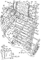
- the apparatus 20 has conveyor means 22 which deliver a stream or a plurality of articles 24 following a path of travel 26 for packaging.
- Articles 24 enter the apparatus 20 at an input end 28, are moved along the path of travel 26, and, after being packaged, exit at the output end 30 as discrete packages 32 of articles 24.
- An electronic controller 34 of known construction including graphics display 35 with function keys 36 and data collection is utilized to control the apparatus 20.
- Fig. 2 provides a plan view of the apparatus 20 as shown in Fig. 1.
- the plan view shows six columns 37 of articles 24 moving along the path of travel 26.
- the six columns 37 are divisible into two lanes 38 each being comprised of three columns 37.
- the articles 24 are transported in the two lanes 38 along the path of travel 26 for assembly with carrier means 40 by assembly means 42.
- Separating means 44 are positioned relative to the two lanes 38 and are moved by drive means 45 which move the separating means 44 synchronous with the conveyor means 22.
- the separating means 44 include reciprocating arms 46 which are positioned between articles 24 moving along the path of travel 26. Articles 24 positioned between two arms 46 form a group 48 of articles 24 to be packaged with the carrier means 40.
- the carrier means 40 is comprised of a carrier strip 50 formed of a flexible, resilient plastic sheet material having a longitudinal series of transverse article retaining bands 51 having band interconnecting portions or interconnections 52 therebetween to form a strip.
- Apertures 53 formed through the bands 51 generally are not shaped or sufficiently large to receive the articles 24 with which they are assembled. Rather, the bands 51 are formed of a resilient material such that when stretched, the stretched aperture 53 closely engages an outside surface 55 of the article 24 with which it is assembled.
- the carrier strip 50 shown in FIG. 10 is an illustrative composite showing two forms of band interconnections 52; a narrowed neck-like isthmul portion 54a on the right side of FIG. 10, and a continuous connected portion 54b on the left side of FIG. 10.
- the continuous connected portion 54b is formed by extensions of opposed bands 51 generally continuously extending therebetween.
- Both forms of band interconnections 52 extend from opposed bands 51 to meet forming a connection therebetween.
- the interconnections 52 may be formed between every row of bands or a predetermined periodic interval, for example every two rows. Perforated or otherwise weakened tear lines 57 are formed along the interconnections 52 to facilitate separation of the groups 48 of articles 24 assembled with the carrier strip 50 into discrete packages 32 of articles 24.
- a reel 58 of the carrier strip 50 is delivered by delivery means 60 to the assembly means 42.
- a plurality of articles 24 move along the path of travel 26 through the assembly means 42 whereupon they are assembled with the carrier strip 50 and separated into discrete packages 32.
- the separating means 44 include a common flight 62 which is driven by sprockets 64 attached to the drive means 45.
- the arms 46 are attached to the common flight 62 for positioning between groups 48 of articles 24 on the fly.
- the common flight 62 is synchronized with the conveyor means 22 so that the arms 46 reciprocally attached thereto are easily insertable between articles 24 moving along the path of travel 26.
- Fig. 4 provides an enlarged perspective view looking towards the assembly means 42 from the input end 28. It should be noted that articles 24 have been removed from the lane 38 in the foreground of the view in order to clearly illustrate the operation of the separating means 44. Further, articles 24 have been removed from the background to clearly illustrate movement of the arms 46 through passages 65 formed in column dividers 66 positioned in the lanes 38.
- the common flight 62 is a chain conveyor including two chains, an inside chain 67 parallely positioned along side of the conveyor means 22 and an outside chain 68 parallelly positioned along side and spaced apart from the inside chain 67.
- Footing blocks 69 are mounted at periodic spacings on a conveyor facing edge 70 of the outside chain 68 and an outwardly facing edge 71 of the inside chain 67 along the common flight 62.
- Rails 72 are attached to opposing pairs of footing blocks 69 generally perpendicularly between the pair of common flight 62 chains 67, 68. The rails 72 provide a structure capable of moving with the common flight 62 while providing a support on which the arms 46 reciprocate.
- Reciprocating means 73 include a generally "L"-shaped body portion 75 and rotatable wheels 74.
- the wheels 74 are mounted to the body portion 75 and engage the rail 72. With the arm 46 mounted to the body portion 75, movement of the body portion 75 results in movement of the arm 46 thereattached.
- Each body portion 75 of the reciprocating means 73 has a cam pin 76 attached to the underside thereof.
- the cam pin 76 movably engages a camming track 78 which is generally non-parallely directed with respect to the conveyor 22 resulting in reciprocally urging the arm 46 in between or out from a group 48 of articles 24.
- the arms 46 are relatively flat generally rigid elongate members. When fully extended perpendicularly across the path of travel 26, a length dimension 79 of the arm sufficiently spans the entire width of the path of travel 26. As well as reciprocally inserting in between groups of articles 48 (as indicated by arrow 80), the arms 46 travel synchronously in the direction of the path of travel 26 generally in close relation to a top surface 81 of the conveyor means 22. In the present embodiment, a height dimension 82 of the arms 46 is at least less than one-half of the article height, but may be shorter or taller than conventional articles. Dimensioned as such, the arms 46 helps support and move articles 24 in the direction of the path of travel 26 as well as retain the articles 24 in upright parallel alignment.
- a locking tip 90 formed on a free end 91 of the arm 46 mates with a cooperatively dimensioned and positioned notch 92 formed on a notched footing block 93 positioned on the inside edge 88 of the conveyor 22. Engagement of the locking tip 90 with the notch 92 prohibits flexing of the arm 46 against the path of travel 26 thereby increasing retention of the group 48 of articles 24 in close relation.
- friction reducing material 96 is attached or applied to article abutting surfaces 94 of the arm.
- the friction reducing material 96 prevents damage to the outside surface 55 of the articles 24 positioned thereagainst.
- the friction reducing material 96 therefore promotes grouping of the articles 24, protection of the outside surfaces 55 of the articles 24 and protection of the assembly process by preventing damage to the articles 24 the contents of which could impair the operation of and hence the processing rate of the apparatus 20.
- a blade member 100 extends upwardly away from the top edge 84 of the arm 46. As illustrated and described in greater detail hereinbelow, the blade member 100 promotes separation of the groups 48 of articles 24 once the carrier strip 50 is assembled therewith.
- the blade member 100 is attached to the arm 46 towards the free end 91 and has a leading edge 102 shaped to promote separation of the carrier strip 50 upon extraction of the arm 46.
- An angle 104 generally equal to or less than 90° is formed between the leading edge 102 and the top edge 84 of the arm 46. This angle 104 promotes retention of the carrier 50 on the articles 24 assembled therewith by preventing the carrier material 50 from being forced upwardly along the outside surface 55 of the articles 24 as the arm 46 is extracted from between a group 48 of articles 24.
- Fig. 4 further illustrates the relative movement of the various components of the apparatus 20 from the input end 28.
- the general direction of movement in this area 28 is coincident with the path of travel 26.
- the conveyor means 22, the inside chain 67 and outside chain 68 of the common flight 62, as well as the attached separating means 44 components and the notched blocks 93 synchronously move along a common path of travel 26.
- the camming track 78 is angled inwardly towards the conveyor means 22 such that the reciprocating means 73 follow an angular path inwardly towards the conveyor means 22 along the path of travel 26.
- the angular movement of the reciprocating means 73 moves the arms 46 attached thereto in a perpendicular direction 80 relative the path of travel 26 while moving synchronously in the path of travel 26.
- Assembly means 42 include a rotary application drum 105 which rotates in a complementary direction to the path of travel 26 to assemble the carrier strip 50 retained thereon with the articles 24 moving thereunder.
- the carrier strip 50 is retained on the rotary application drum 105 by a carrier engaging assembly or application jaw stations 106.
- the application jaw stations 106 are a combination of reciprocal jaws 108 positioned along an outside edge 110 of the drum 105 and stationery jaws 112 fixedly positioned along a central portion 114 of the drum 105. With the jaws 108, 112 projecting through the outer most apertures 53 of the carrier strip 50, the reciprocal jaws 108 are outwardly cammed, as indicated by the arrow 118, stretching the carrier 50 away from the stationery jaw 112. By stretching the carrier 50, the apertures 53 formed therethrough are sufficiently enlarged to permit assembly of the carrier 50 with the articles 24. Further detail of the structure of the application jaw stations 106 is provided hereinbelow in the description accompanying Figs. 6 and 7.
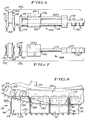
- Figs. 6 and 7 provide enlarged side and bottom views of the application jaw stations 106.
- the application jaw stations 106 are mounted to the rotary application drum 105 and have reciprocal jaw portions 108 which are cammingly moved to stretch the carrier 50.
- Each of the application jaw stations 106 is comprised of a stationary block 120 mounted on the central portion 114 of the drum 105 to which is stationarily mounted a pair of opposed jaw plates 122.
- Each stationary jaw plate 122 has a corresponding cooperatively positioned reciprocal jaw assembly 108 mounted generally on the outside of the rotary application drum 105. It is to be noted that Figs. 6 and 7 only illustrate one reciprocal jaw 108 and both stationary jaws 112 of the application jaw stations 106.
- the reciprocal jaw 108 is secured to the rotary application drum 105 by mounting block 124 which has two bores 126 formed therethrough.
- the jaw plate 122 of the reciprocal jaw 108 is secured to a pair of operating rods 128 which are radially or vertically stacked relative to an axis 129 of the drum 105 permitting closer spacing of the application jaw stations 106 around the circumference of the rotary application drum 105 and providing sufficient clearance for arms 46.
- the operating rods 128 project through and are slidably retained within the corresponding bores 126. Ends of the operating rods 128 distal the jaw plate 122 are secured to a cam follower block 130.
- the cam follower block 130 is formed with rollers 132 which follow a camming track positioned near the outermost edge of the rotary application drum 105.
- the camming track is angled inwardly towards and outwardly away from the articles 24 moving underneath the rotary application drum 105 to urge the reciprocal jaw 108 inwardly towards the centre of the drum 105 and outwardly therefrom via mechanical engagement with the rollers 132.
- the camming track (not shown, but similar in operation to the mechanisms as shown in US-A-4,250,682 to Braun) is angled inwardly towards the drum 105, the reciprocal jaw 108 is slidably moved towards the stationary jaw 112.
- the carrier material 50 is positioned over fingers 134 on the respective jaw plates 122.
- the camming track angles outwardly away from the stationary jaw 112 thereby moving the jaw plate 122 of the reciprocal jaw 108 away from the stationary jaw 112.
- the carrier material positioned on the respective fingers 134 thereof is stretched to enlarge the apertures 53 a sufficient dimension to permit assembly with articles 24.
- the positioning of the carrier material 50 on the application jaw stations 106 and stretching of the carrier material 50 is performed in a high speed rotary motion as the application jaws 106 are mounted to the outer surface of the rotary application drum 105.
- the apertures 53 are positioned over corresponding articles 24 moving thereunder.
- Fig. 8 provides greater detail of the point at which the carrier material 50 is assembled with the articles 24 moving thereunder.
- the view illustrated in Fig. 8 is taken looking towards the central portion 114 of the drum 105 through a single column of articles 37 moving along the path of travel 26.
- the stationary jaws 112 include the jaw plate 122 mounted to the stationary jaw block 120 and the corresponding fingers 134.
- Carrier material 50 is stretched and retained on the stationary fingers 134 and positioned over a top portion 136 of the articles 24 moving thereunder.
- the diameter of the application drum 105 permits a shallow angle of approach or slope in applying the carrier material 50 over tops 136 of the articles 24.
- the diameter of the rotary drum 105 is dimensioned to permit delivery of the carrier material 50 to a midpoint 135 positioned substantially spaced from top and bottom portions 136, 137 of the articles 24.
- the application drum 105 is eliminated and the application jaw stations 106 are mounted to a moving flight or other moving application jaw stations 106 retaining structure. Use of an alternative to the drum 105 decreases the angle of approach of the carrier material 50 being applied to the articles 24.
- a fin 138 helps to position the carrier downwardly onto the outside surfaces 55 of the articles 24.
- the fin 138 in frictional engagement between the carrier bands and surfaces 55 assists in peeling the carrier 50 off of the jaw fingers 134 as the rotary application drum 105 sweeps the application jaw stations 106 upwardly away from the articles 24 in a rotary motion.
- the fin 138 is formed with a gently sloping leading edge 140 providing minimum interference with the application jaw stations 106 and the carrier material 50 retained therebetween.
- the exit side of the blade 138 is likewise curved to prevent snagging of the carrier material 50 as it peels from the application jaw stations 106.
- the arm 46 positioned between groups 48 of articles 24 is extracted from between the group 48 of articles 24.
- a passage notch 142 is formed through the fin 138. The passage notch 142 is positioned at an appropriate location determined by the path of travel of the arm 46 being extracted from between the groups 48 of articles 24 as the articles 24 move along the path of travel 26.
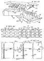
- FIG. 9 As shown in Fig. 9, two fins 138 separate each lane 38 into three (3) single article columns 37.
- the fins 138 illustrated in Fig. 9 are formed with passage notches 142 to permit movement therethrough of the upstanding blade portion 100 mounted to the top 84 of the arm 46.
- articles 24 have been omitted from Fig. 9, it can be seen that the reciprocal arms 46 are fully extracted from out of the path of travel 26 at the output end 32 of the apparatus 20.
- the footing blocks 69 along the outside edge 86 of the conveyor 22 and the notched footing blocks 93 along the inside edge 88 of the conveyor 22 are rotated downwardly away from the top 81 of the conveyor 22 since they are attached to the synchronized common flight 62 which is engaged with a sprocket 64 or other drive means 45 for moving the common flight 62.
- Fig. 11 provides an enlarged side elevational view of a plurality of articles 24 having a reciprocal arm 46 (shown in cross section) being extracted from therebetween.
- various portions of the apparatus 20 have been omitted in order to provide greater clarity in describing the means and function of the present invention.
- the carrier 50 is positioned substantially from the top 136 and the bottom 137 of the articles 24, such position in part being determined and maintained by the fin 138 described above.
- the strip of carrier material 50 assembled with the articles 24 as such defines a plane 143 through which the blade 100 upwardly projects.
- the carrier 50 is generally formed of a thin sheet material such as 0.3mm (0.012 mil) to 0.4mm (0.016 mil) polyethylene such that when apertures 53 are formed therethrough, the retaining bands 51 have a width dimension or band surface 144 which is greater than the thickness of the carrier material 50.
- the band surface 144 lies flat against the outside surface 55 of the article 24 and an internal edge 146 of the aperture 53 is oriented in an upward direction but is not positioned directly under the chime 147 of the article 24 as typified in prior art packages.
- FIG. 12 A top view of the arrangement as illustrated in Fig. 11 is shown in Fig. 12.
- the arm 46 is engaged with the camming track 78 by the camming pin 76 attached to the L-shaped body portion 75.
- the camming track 78 is angled away from the path of travel 26 thereby extracting the arm 46 from between the groups 48 of articles 24.
- the locking tip 90 is shown as having been disengaged from the locking notch 92 formed in the corresponding notched block 93.
- the extraction path 152 passes through the passage notches 142 formed in the fins 138 as noted hereinabove.
- the leading edge 102 of the blade 100 passes through perforated or weakened line 57 formed in the band interconnections 52 to separate the groups 48 of articles 24.
- the leading edge 102 although bevelled, is not sufficiently sharp to cut the carrier material 50.
- the edge 102 is preferably blunt so as to promote a tearing or separating action rather than a cutting action.
- the effect of the blade 100 attached to the reciprocal arm 46 moving along the weakened lines 57 formed along the band interconnections 52 of the carrier 50 results in unzipping groups 48 of articles 24.
- the blade 100 performs the function of a slider which separates opposed joined structures (i.e. the band interconnections 52).
- the blade 100 unzips the carrier material 50 joined at the band interconnections 52. Weakening of the material by perforating or forming weakened lines 57 further facilitates the unzipping action and function of the separating means 44.
- Fig. 13 provides an enlarged perspective view of the blade 100 moving through the band interconnections 52 as illustrated in Fig. 12.
- the band surfaces 144 lie against the outside surface 55 of the articles 24.
- the internal edge 146 of the aperture 53 is shown in its upward orientation.
- the article 24 in the foreground of the perspective view has been removed to provide clarity in the illustration, the outside surface 55 of the article 24 in the foreground abuts the friction reducing material 96 on the outside of the arm 46 placing the corresponding band interconnection 52 in tension to promote the unzipping or separation of the carrier material 50 along the weakened line 57 by the leading edge 102.
- the angle 104 of the blade member 100 being generally equal to or less than 90° does not urge the carrier upwardly as the arm 46 is extracted from between the groups of articles 48.
- the angle 104 between the blade 100 and the arm 46 is important when the leading edge 102 does not cut through the carrier material 50.
- the frictional forces between the leading edge 102 may become greater than the frictional forces between an inwardly facing surface 154 of the band surface 144 and the abutting outside surface 55 of the article 24 which could cause the carrier to move upwardly out of the desired position.
- a group 48 of articles 24 is illustrated in Fig. 14, wherein 12 articles have been grouped together as a discrete package 32 of articles 24 retained by a common portion of carrier 50.
- a "12-pak” can be created by selectively engaging or activating the cam pin 76 of every other arm 46 on the apparatus as arranged in Fig. 4 instead of every arm as illustrated.
- every other arm 46 could be removed from the common flight 62 such that 12 articles are positioned between every two arms 46.
Landscapes
- Engineering & Computer Science (AREA)
- Mechanical Engineering (AREA)
- Auxiliary Devices For And Details Of Packaging Control (AREA)
- Packages (AREA)
- Supplying Of Containers To The Packaging Station (AREA)
- Packaging For Recording Disks (AREA)
- Piezo-Electric Or Mechanical Vibrators, Or Delay Or Filter Circuits (AREA)
- Battery Mounting, Suspending (AREA)
- Container Filling Or Packaging Operations (AREA)
- Control And Other Processes For Unpacking Of Materials (AREA)
- Chain Conveyers (AREA)
- Closing Of Containers (AREA)
Claims (9)
- Appareil (20) d'assemblage de plusieurs objets (24) à des supports disposés en une bande (50) de supports reliés et de séparation de l'ensemble résultant en paquets individuels (32) dont chacun consiste en plusieurs des objets (24) réunis par un unique support, l'appareil comprenant un moyen transporteur (22) pour déplacer les objets (24) le long d'un trajet d'avance (26) ; un moyen d'assemblage (42) voisin du trajet d'avance (26) pour assembler les supports (50) avec les objets (24) ; et un moyen de séparation consistant en un élément de lame (100) pour séparer l'ensemble résultant en paquets individuels (32), le moyen de séparation (44) pouvant être positionné entre des objets (24) se déplaçant le long du trajet d'avance (26) ;
caractérisé en ce que le moyen de séparation (44) introduit latéralement entre objets voisins (24) disposés en un flux continu augmente la traction de la bande (50) de supports lorsqu'il est en place et, au moment auquel il est extrait transversalement et horizontalement par rapport au trajet d'avance (26), l'élément de lame (100) sépare l'ensemble en paquets individuels. - Appareil selon la revendication 1, dans lequel la bande (50) de supports comprend des lignes de faiblesse (57) qui sont rompues par le moyen de séparation (44) afin de séparer l'ensemble en paquets individuels.
- Appareil selon la revendication 2, dans lequel les parties de liaison du support (50) ayant des lignes de faiblesse (57) sont périodiquement écartées d'un bord latéral vers un bord latéral opposé, les parties de liaison écartées formant des parties en isthme entre elles, ou dans lequel les parties de liaison du support (50) ayant des lignes de faiblesse (57) sont des parties de liaison sensiblement continues se prolongeant en continu entre supports successifs d'un bord de la bande au bord opposé de celle-ci.
- Appareil selon l'une quelconque des revendications précédentes, dans lequel le moyen d'assemblage (42) comprend un moyen de positionnement (138) pour positionner les supports sensiblement à distance, et entre le sommet et le fond, des objets (24).
- Appareil selon l'une quelconque des revendications précédentes, dans lequel le moyen de séparation comprend une volée commune (62) placée le long d'au moins un côté du trajet d'avance (26) et synchronisée avec les objets (24) se déplaçant le long de ce dernier, une série de bras (46) reliés fonctionnellement à la volée commune (62) pour être introduits entre les objets (24) se déplaçant le long du trajet d'avance (26), une extrémité libre de chaque bras (46), qui est distante de la volée commune, comprend l'élément de lame (100) qui passe à travers un plan formé par les supports (50) assemblés avec les objets (24) et des moyens de production de mouvements alternatifs (76, 78) pour déplacer horizontalement et transversalement les bras (46) entre les objets (24) se déplaçant le long du trajet d'avance (26) de façon que, lorsque les bras (46) sont extraits horizontalement et transversalement d'entre les objets (26), la matière de support (50) soit séparée pour former des paquets individuels (32).
- Appareil selon la revendication 5, dans lequel le moyen de séparation (44) est disposé de manière que le bord de tête (102) de l'élément de lame (100) forme un angle égal ou inférieur à 90° avec la direction du mouvement transversal du bras (46) pour empêcher le support (50) de se déplacer vers le haut le long des objets (24) lorsque le support (50) est rompu.
- Appareil selon la revendication 5 ou 6, dans lequel le bras (46) est revêtu d'une matière (96) qui abaisse le frottement.
- Appareil selon les revendications 5, 6 ou 7, dans lequel le moyen de séparation (44) comprend par ailleurs des moyens (93) de logement de bras positionnés en synchronisme le long du trajet d'avance (26) en face de l'extrémité libre des bras (46) pour loger et retenir de manière amovible l'extrémité libre des bras (46) après que les bras (46) ont été insérés entre les objets (24), chacun des moyens de logement de bras (93) comportant une encoche (92) calibrée et dimensionnée pour loger l'extrémité libre de manière à empêcher la flexion des bras (46) lorsqu'ils ont été introduits entre les objets (24).
- Appareil selon les revendications 5, 6, 7 ou 8, dans lequel les bras (46) sont actionnés sélectivement par la volée commune pour commander de manière réglable le nombre d'objets (24) des groupes successifs d'objets (24) entre lesquels les bras (46) sont positionnés.
Applications Claiming Priority (2)
| Application Number | Priority Date | Filing Date | Title |
|---|---|---|---|
| US519860 | 1990-05-07 | ||
| US07/519,860 US5117609A (en) | 1990-05-07 | 1990-05-07 | Apparqus and method for applying a multi-package carrier |
Publications (2)
| Publication Number | Publication Date |
|---|---|
| EP0456357A1 EP0456357A1 (fr) | 1991-11-13 |
| EP0456357B1 true EP0456357B1 (fr) | 1996-06-12 |
Family
ID=24070110
Family Applications (1)
| Application Number | Title | Priority Date | Filing Date |
|---|---|---|---|
| EP91303390A Expired - Lifetime EP0456357B1 (fr) | 1990-05-07 | 1991-04-17 | Dispositif pour appliquer une élément porteur pour plusieurs récipients |
Country Status (18)
| Country | Link |
|---|---|
| US (1) | US5117609A (fr) |
| EP (1) | EP0456357B1 (fr) |
| JP (1) | JP3280679B2 (fr) |
| KR (1) | KR0178028B1 (fr) |
| CN (1) | CN1023989C (fr) |
| AT (1) | ATE139194T1 (fr) |
| AU (1) | AU642723B2 (fr) |
| BR (1) | BR9101751A (fr) |
| CA (1) | CA2040662C (fr) |
| DE (1) | DE69120145T2 (fr) |
| DK (1) | DK0456357T3 (fr) |
| ES (1) | ES2087970T3 (fr) |
| FI (1) | FI93815C (fr) |
| GR (1) | GR3020217T3 (fr) |
| IE (1) | IE76317B1 (fr) |
| NO (1) | NO300315B1 (fr) |
| NZ (1) | NZ237890A (fr) |
| PT (1) | PT97599B (fr) |
Cited By (1)
| Publication number | Priority date | Publication date | Assignee | Title |
|---|---|---|---|---|
| DE102009026113A1 (de) | 2009-07-07 | 2011-01-13 | Krones Ag | Schneidscheibe, Schneidvorrichtung und Verfahren zum Vereinzeln von Gebindeeinheiten |
Families Citing this family (19)
| Publication number | Priority date | Publication date | Assignee | Title |
|---|---|---|---|---|
| JPH09501889A (ja) * | 1992-06-02 | 1997-02-25 | ミネソタ マイニング アンド マニュファクチャリング カンパニー | 可変伸張低粘着化粘着テープによる一体化システム |
| US5383321A (en) * | 1993-06-21 | 1995-01-24 | Illinois Tool Works Inc. | Machine for applying carrier stock to containers, such as beverage cans, selectively in rim-applied or side-applied carrier position |
| US5542231A (en) * | 1995-08-23 | 1996-08-06 | Illinois Tool Works Inc. | Apparatus for adapting carrier stock-applying machine to apply carrier stock having container-engaging and handle portions. |
| US6588173B1 (en) * | 2002-02-21 | 2003-07-08 | Illinois Tool Works Inc. | Machine for packaging containers |
| US6973760B2 (en) * | 2002-02-21 | 2005-12-13 | Ilinois Tool Works, Inc. | Machine for packaging containers |
| US20040005429A1 (en) * | 2002-07-03 | 2004-01-08 | Slaters Arthur R. | Index control of punched carriers for containers |
| US7637077B2 (en) * | 2006-05-09 | 2009-12-29 | Illinois Tool Works Inc. | Applicating machine |
| US20090094938A1 (en) * | 2007-10-05 | 2009-04-16 | Biernat Krzysztof P | Applicating machine |
| US8112970B2 (en) * | 2007-10-05 | 2012-02-14 | Illinois Tool Works Inc. | Flexible carrier and system for application to a plurality of containers |
| DE102009040700A1 (de) * | 2009-09-10 | 2011-03-24 | Krones Ag | Verfahren und Vorrichtung zur Herstellung von Gebinden |
| GB0920396D0 (en) * | 2009-11-23 | 2010-01-06 | Dijofi Ltd | A plastics container carrier |
| GB201019848D0 (en) | 2010-11-23 | 2011-01-05 | Dijofi Ltd | A machine and system for applying container carriers to containers |
| EP3974329A1 (fr) | 2019-05-17 | 2022-03-30 | Krones Aktiengesellschaft | Procédé et dispositif de fabrication d'un emballage multiple pourvu d'une pluralité de récipients de boissons |
| DE102019128705A1 (de) | 2019-10-24 | 2021-04-29 | Krones Ag | Verfahren zum Herstellen eines Multipacks mit mehreren Getränkebehältern und Multipack mit mehreren Getränkebehältern |
| CN111296305B (zh) * | 2020-03-03 | 2021-07-13 | 安徽农业大学 | 一种移动方便的宠物物流安全运输箱 |
| GB2597971B (en) * | 2020-08-12 | 2024-03-20 | British Polythene Ltd | Improvements in or relating to container carriers |
| US11905052B2 (en) | 2021-04-13 | 2024-02-20 | Douglas Machine Inc. | System and process for forming retained container groups from arrayed container groups |
| DE102021129507A1 (de) | 2021-11-12 | 2023-05-17 | Krones Aktiengesellschaft | Multipack und Verfahren zum Herstellen eines Multipacks |
| US12522412B2 (en) | 2023-04-19 | 2026-01-13 | Illinois Tool Works Inc. | Container carrier |
Family Cites Families (19)
| Publication number | Priority date | Publication date | Assignee | Title |
|---|---|---|---|---|
| US3032943A (en) * | 1960-08-12 | 1962-05-08 | James L Reimers | Assembly machine |
| US3204386A (en) * | 1962-02-19 | 1965-09-07 | Illinois Tool Works | Container pack forming machine |
| US3328937A (en) * | 1964-10-14 | 1967-07-04 | Unit Portions Inc | Device for continuously feeding and packaging flowable substances |
| US3557651A (en) * | 1968-12-23 | 1971-01-26 | United States Gypsum Co | Film-cutting apparatus |
| US3611656A (en) * | 1970-04-24 | 1971-10-12 | Container Corp | Method and apparatus for forming carriers for container groups |
| US3792562A (en) * | 1972-01-10 | 1974-02-19 | Container Corp | Method of packaging grouped articles |
| BE791329A (fr) * | 1972-09-18 | 1973-03-01 | Illinois Tool Works | Assemblage |
| US3959949A (en) * | 1975-06-02 | 1976-06-01 | Illinois Tool Works Inc. | System, machine and method for multipackaging containers |
| US4018331A (en) * | 1975-05-29 | 1977-04-19 | Illinois Tool Works Inc. | Multipackaging devices |
| US3991640A (en) * | 1976-01-21 | 1976-11-16 | Illinois Tool Works Inc. | Package forming machine |
| US4079571A (en) * | 1976-03-15 | 1978-03-21 | Illinois Tool Works Inc. | Package forming machine |
| US4024950A (en) * | 1976-06-21 | 1977-05-24 | Adolph Coors Company | Multi-container package |
| DE3063941D1 (en) * | 1979-03-13 | 1983-08-04 | Plg Res | A container pack, a device and band for holding containers together and method of making the same |
| US4250682A (en) * | 1979-07-19 | 1981-02-17 | Illinois Tool Works Inc. | Wheel assembly for use in an apparatus for multipackaging containers |
| US4953342A (en) * | 1982-07-01 | 1990-09-04 | Hynes Charles M | Multi package containers |
| US4462494A (en) * | 1983-01-24 | 1984-07-31 | Grip-Pak, Inc. | Multi-packaging device for cylindrical containers |
| US4530264A (en) * | 1983-06-30 | 1985-07-23 | Illinois Tool Works Inc. | Carrier cutting wheel |
| DE3837460A1 (de) * | 1988-11-04 | 1990-05-10 | Sieger Plastic Gmbh | Trennvorrichtung zum abtrennen von endlos gefertigten bag-in-box-beuteln von einer beutelbahn |
| US5054257A (en) * | 1989-07-27 | 1991-10-08 | Grip-Pak, Inc. | Cut-off device for can-container packaging equipment |
-
1990
- 1990-05-07 US US07/519,860 patent/US5117609A/en not_active Expired - Lifetime
-
1991
- 1991-04-15 AU AU74374/91A patent/AU642723B2/en not_active Ceased
- 1991-04-17 DE DE69120145T patent/DE69120145T2/de not_active Expired - Fee Related
- 1991-04-17 EP EP91303390A patent/EP0456357B1/fr not_active Expired - Lifetime
- 1991-04-17 DK DK91303390.8T patent/DK0456357T3/da active
- 1991-04-17 CA CA002040662A patent/CA2040662C/fr not_active Expired - Fee Related
- 1991-04-17 ES ES91303390T patent/ES2087970T3/es not_active Expired - Lifetime
- 1991-04-17 AT AT91303390T patent/ATE139194T1/de not_active IP Right Cessation
- 1991-04-19 NZ NZ237890A patent/NZ237890A/xx unknown
- 1991-04-27 CN CN91102737A patent/CN1023989C/zh not_active Expired - Fee Related
- 1991-04-30 BR BR919101751A patent/BR9101751A/pt not_active IP Right Cessation
- 1991-05-01 JP JP12655791A patent/JP3280679B2/ja not_active Expired - Fee Related
- 1991-05-06 NO NO911766A patent/NO300315B1/no unknown
- 1991-05-06 KR KR1019910007288A patent/KR0178028B1/ko not_active Expired - Fee Related
- 1991-05-06 IE IE152291A patent/IE76317B1/en not_active IP Right Cessation
- 1991-05-07 FI FI912198A patent/FI93815C/fi active
- 1991-05-07 PT PT97599A patent/PT97599B/pt not_active IP Right Cessation
-
1996
- 1996-06-13 GR GR950403369T patent/GR3020217T3/el unknown
Cited By (1)
| Publication number | Priority date | Publication date | Assignee | Title |
|---|---|---|---|---|
| DE102009026113A1 (de) | 2009-07-07 | 2011-01-13 | Krones Ag | Schneidscheibe, Schneidvorrichtung und Verfahren zum Vereinzeln von Gebindeeinheiten |
Also Published As
| Publication number | Publication date |
|---|---|
| FI93815C (fi) | 1995-06-12 |
| ES2087970T3 (es) | 1996-08-01 |
| ATE139194T1 (de) | 1996-06-15 |
| JPH0776313A (ja) | 1995-03-20 |
| EP0456357A1 (fr) | 1991-11-13 |
| IE911522A1 (en) | 1991-11-20 |
| BR9101751A (pt) | 1991-12-10 |
| GR3020217T3 (en) | 1996-09-30 |
| FI912198A0 (fi) | 1991-05-07 |
| IE76317B1 (en) | 1997-10-22 |
| CN1056283A (zh) | 1991-11-20 |
| FI912198L (fi) | 1991-11-08 |
| CA2040662C (fr) | 1998-10-06 |
| NO300315B1 (no) | 1997-05-12 |
| DK0456357T3 (da) | 1996-10-21 |
| KR0178028B1 (ko) | 1999-04-15 |
| CA2040662A1 (fr) | 1991-11-08 |
| NO911766D0 (no) | 1991-05-06 |
| AU642723B2 (en) | 1993-10-28 |
| PT97599A (pt) | 1993-07-30 |
| DE69120145D1 (de) | 1996-07-18 |
| NO911766L (no) | 1991-11-08 |
| FI93815B (fi) | 1995-02-28 |
| AU7437491A (en) | 1991-11-07 |
| PT97599B (pt) | 1999-03-31 |
| DE69120145T2 (de) | 1996-10-24 |
| US5117609A (en) | 1992-06-02 |
| KR910019853A (ko) | 1991-12-19 |
| NZ237890A (en) | 1992-12-23 |
| CN1023989C (zh) | 1994-03-16 |
| JP3280679B2 (ja) | 2002-05-13 |
Similar Documents
| Publication | Publication Date | Title |
|---|---|---|
| EP0456357B1 (fr) | Dispositif pour appliquer une élément porteur pour plusieurs récipients | |
| US20230294222A1 (en) | Article Selection And Placement Assembly And Method | |
| US3742677A (en) | Method and apparatus for applying a carrier to a cluster of containers | |
| US4121401A (en) | Method and apparatus for applying reinforcing strips to adjacent pairs of containers | |
| EP1758804B1 (fr) | Ensemble rail guide de chaine de manipulation automatique | |
| US4354333A (en) | Packaging apparatus | |
| US4689934A (en) | Apparatus for and method of applying wrap to article clusters | |
| EP0216512B1 (fr) | Emballages multiples et dispositifs porteurs, machines et procédés pour leur fabrication | |
| US4817361A (en) | Carrier assembling apparatus | |
| NL8101838A (nl) | Verpakkingsinrichting. | |
| US4953342A (en) | Multi package containers | |
| US5065565A (en) | Method and apparatus for applying carriers to containers |
Legal Events
| Date | Code | Title | Description |
|---|---|---|---|
| PUAI | Public reference made under article 153(3) epc to a published international application that has entered the european phase |
Free format text: ORIGINAL CODE: 0009012 |
|
| AK | Designated contracting states |
Kind code of ref document: A1 Designated state(s): AT BE CH DE DK ES FR GB GR IT LI LU NL SE |
|
| 17P | Request for examination filed |
Effective date: 19920508 |
|
| 17Q | First examination report despatched |
Effective date: 19950315 |
|
| GRAH | Despatch of communication of intention to grant a patent |
Free format text: ORIGINAL CODE: EPIDOS IGRA |
|
| GRAH | Despatch of communication of intention to grant a patent |
Free format text: ORIGINAL CODE: EPIDOS IGRA |
|
| GRAA | (expected) grant |
Free format text: ORIGINAL CODE: 0009210 |
|
| AK | Designated contracting states |
Kind code of ref document: B1 Designated state(s): AT BE CH DE DK ES FR GB GR IT LI LU NL SE |
|
| PG25 | Lapsed in a contracting state [announced via postgrant information from national office to epo] |
Ref country code: CH Effective date: 19960612 Ref country code: BE Effective date: 19960612 Ref country code: AT Effective date: 19960612 Ref country code: LI Effective date: 19960612 |
|
| REF | Corresponds to: |
Ref document number: 139194 Country of ref document: AT Date of ref document: 19960615 Kind code of ref document: T |
|
| REG | Reference to a national code |
Ref country code: ES Ref legal event code: BA2A Ref document number: 2087970 Country of ref document: ES Kind code of ref document: T3 |
|
| REF | Corresponds to: |
Ref document number: 69120145 Country of ref document: DE Date of ref document: 19960718 |
|
| REG | Reference to a national code |
Ref country code: ES Ref legal event code: FG2A Ref document number: 2087970 Country of ref document: ES Kind code of ref document: T3 |
|
| REG | Reference to a national code |
Ref country code: GR Ref legal event code: FG4A Free format text: 3020217 |
|
| ET | Fr: translation filed | ||
| ITF | It: translation for a ep patent filed | ||
| PG25 | Lapsed in a contracting state [announced via postgrant information from national office to epo] |
Ref country code: SE Effective date: 19960912 |
|
| REG | Reference to a national code |
Ref country code: DK Ref legal event code: T3 |
|
| REG | Reference to a national code |
Ref country code: CH Ref legal event code: PL |
|
| PLBE | No opposition filed within time limit |
Free format text: ORIGINAL CODE: 0009261 |
|
| STAA | Information on the status of an ep patent application or granted ep patent |
Free format text: STATUS: NO OPPOSITION FILED WITHIN TIME LIMIT |
|
| PG25 | Lapsed in a contracting state [announced via postgrant information from national office to epo] |
Ref country code: LU Free format text: LAPSE BECAUSE OF NON-PAYMENT OF DUE FEES Effective date: 19970430 |
|
| 26N | No opposition filed | ||
| REG | Reference to a national code |
Ref country code: GB Ref legal event code: IF02 |
|
| PGFP | Annual fee paid to national office [announced via postgrant information from national office to epo] |
Ref country code: NL Payment date: 20070424 Year of fee payment: 17 |
|
| PGFP | Annual fee paid to national office [announced via postgrant information from national office to epo] |
Ref country code: DK Payment date: 20070430 Year of fee payment: 17 |
|
| PGFP | Annual fee paid to national office [announced via postgrant information from national office to epo] |
Ref country code: DE Payment date: 20070531 Year of fee payment: 17 |
|
| PGFP | Annual fee paid to national office [announced via postgrant information from national office to epo] |
Ref country code: GB Payment date: 20070425 Year of fee payment: 17 |
|
| PGFP | Annual fee paid to national office [announced via postgrant information from national office to epo] |
Ref country code: IT Payment date: 20070523 Year of fee payment: 17 |
|
| PGFP | Annual fee paid to national office [announced via postgrant information from national office to epo] |
Ref country code: GR Payment date: 20070430 Year of fee payment: 17 |
|
| REG | Reference to a national code |
Ref country code: DK Ref legal event code: EBP |
|
| GBPC | Gb: european patent ceased through non-payment of renewal fee |
Effective date: 20080417 |
|
| NLV4 | Nl: lapsed or anulled due to non-payment of the annual fee |
Effective date: 20081101 |
|
| PG25 | Lapsed in a contracting state [announced via postgrant information from national office to epo] |
Ref country code: NL Free format text: LAPSE BECAUSE OF NON-PAYMENT OF DUE FEES Effective date: 20081101 Ref country code: DE Free format text: LAPSE BECAUSE OF NON-PAYMENT OF DUE FEES Effective date: 20081101 |
|
| PG25 | Lapsed in a contracting state [announced via postgrant information from national office to epo] |
Ref country code: DK Free format text: LAPSE BECAUSE OF NON-PAYMENT OF DUE FEES Effective date: 20080430 |
|
| PG25 | Lapsed in a contracting state [announced via postgrant information from national office to epo] |
Ref country code: GB Free format text: LAPSE BECAUSE OF NON-PAYMENT OF DUE FEES Effective date: 20080417 Ref country code: GR Free format text: LAPSE BECAUSE OF NON-PAYMENT OF DUE FEES Effective date: 20081104 |
|
| PGFP | Annual fee paid to national office [announced via postgrant information from national office to epo] |
Ref country code: ES Payment date: 20090427 Year of fee payment: 19 |
|
| PG25 | Lapsed in a contracting state [announced via postgrant information from national office to epo] |
Ref country code: IT Free format text: LAPSE BECAUSE OF NON-PAYMENT OF DUE FEES Effective date: 20080417 |
|
| PGFP | Annual fee paid to national office [announced via postgrant information from national office to epo] |
Ref country code: FR Payment date: 20090417 Year of fee payment: 19 |
|
| REG | Reference to a national code |
Ref country code: FR Ref legal event code: ST Effective date: 20101230 |
|
| REG | Reference to a national code |
Ref country code: ES Ref legal event code: FD2A Effective date: 20110708 |
|
| PG25 | Lapsed in a contracting state [announced via postgrant information from national office to epo] |
Ref country code: ES Free format text: LAPSE BECAUSE OF NON-PAYMENT OF DUE FEES Effective date: 20110628 |
|
| PG25 | Lapsed in a contracting state [announced via postgrant information from national office to epo] |
Ref country code: ES Free format text: LAPSE BECAUSE OF NON-PAYMENT OF DUE FEES Effective date: 20100418 |
|
| PG25 | Lapsed in a contracting state [announced via postgrant information from national office to epo] |
Ref country code: FR Free format text: LAPSE BECAUSE OF NON-PAYMENT OF DUE FEES Effective date: 20100430 |