EP0216547B1 - Diagnostisches System zur Ermittlung von fehlerhaften Sensoren in einer mit einem Flüssigkeitskühler versehenen Klimaanlage - Google Patents
Diagnostisches System zur Ermittlung von fehlerhaften Sensoren in einer mit einem Flüssigkeitskühler versehenen Klimaanlage Download PDFInfo
- Publication number
- EP0216547B1 EP0216547B1 EP86306851A EP86306851A EP0216547B1 EP 0216547 B1 EP0216547 B1 EP 0216547B1 EP 86306851 A EP86306851 A EP 86306851A EP 86306851 A EP86306851 A EP 86306851A EP 0216547 B1 EP0216547 B1 EP 0216547B1
- Authority
- EP
- European Patent Office
- Prior art keywords
- temperature
- air conditioning
- conditioning system
- evaporator
- refrigerant
- Prior art date
- Legal status (The legal status is an assumption and is not a legal conclusion. Google has not performed a legal analysis and makes no representation as to the accuracy of the status listed.)
- Expired - Lifetime
Links
- 238000004378 air conditioning Methods 0.000 title claims description 32
- 239000007788 liquid Substances 0.000 title claims description 31
- 239000003507 refrigerant Substances 0.000 claims description 34
- 230000000007 visual effect Effects 0.000 claims 1
- XLYOFNOQVPJJNP-UHFFFAOYSA-N water Substances O XLYOFNOQVPJJNP-UHFFFAOYSA-N 0.000 description 17
- 238000012544 monitoring process Methods 0.000 description 6
- 230000004044 response Effects 0.000 description 6
- 230000002950 deficient Effects 0.000 description 4
- 230000000694 effects Effects 0.000 description 3
- 230000006870 function Effects 0.000 description 3
- 238000001816 cooling Methods 0.000 description 2
- 238000006243 chemical reaction Methods 0.000 description 1
- 238000010276 construction Methods 0.000 description 1
- 238000010586 diagram Methods 0.000 description 1
- 238000007710 freezing Methods 0.000 description 1
- 230000008014 freezing Effects 0.000 description 1
- 230000007257 malfunction Effects 0.000 description 1
- 238000000034 method Methods 0.000 description 1
- 238000005057 refrigeration Methods 0.000 description 1
Images


Classifications
-
- F—MECHANICAL ENGINEERING; LIGHTING; HEATING; WEAPONS; BLASTING
- F25—REFRIGERATION OR COOLING; COMBINED HEATING AND REFRIGERATION SYSTEMS; HEAT PUMP SYSTEMS; MANUFACTURE OR STORAGE OF ICE; LIQUEFACTION SOLIDIFICATION OF GASES
- F25B—REFRIGERATION MACHINES, PLANTS OR SYSTEMS; COMBINED HEATING AND REFRIGERATION SYSTEMS; HEAT PUMP SYSTEMS
- F25B49/00—Arrangement or mounting of control or safety devices
-
- F—MECHANICAL ENGINEERING; LIGHTING; HEATING; WEAPONS; BLASTING
- F25—REFRIGERATION OR COOLING; COMBINED HEATING AND REFRIGERATION SYSTEMS; HEAT PUMP SYSTEMS; MANUFACTURE OR STORAGE OF ICE; LIQUEFACTION SOLIDIFICATION OF GASES
- F25B—REFRIGERATION MACHINES, PLANTS OR SYSTEMS; COMBINED HEATING AND REFRIGERATION SYSTEMS; HEAT PUMP SYSTEMS
- F25B49/00—Arrangement or mounting of control or safety devices
- F25B49/005—Arrangement or mounting of control or safety devices of safety devices
Definitions
- This invention relates to an air conditioning system including a diagnostic system for effectively testing the operation of sensors which sense the evaporator refrigerant pressure and the leaving chilled liquid temperature in a livid chiller air conditioning system and for providing a warning when at least one of the sensors is found to be defective.
- centrifugal liquid chillers As the refrigerant flows through the system's evaporator, circulating liquid (usually water), which is in heat exchange relationship with the refrigerant, transfers heat to the refrigerant.
- the chilled liquid leaving the evaporator is then delivered to remote locations and used to cool a building or a zone. By maintaining the temperature of the leaving chilled liquid at a desired setpoint, the cooled space may be held at a desired temperature.
- the required control is usually accomplished by sensing the leaving chilled liquid temperature and adjusting the position of the guide vanes or prerotation vanes, at the inlet of the system's centrifugal compressor, in response to the sensed temperature. Adjusting the prerotation vanes varies the capacity of the centrifugal compressor, which in turn changes the refrigeration capacity of the system.
- a sensor is usually provided to monitor the pressure of the refrigerant in the evaporator. If the evaporator pressure or the leaving chilled liquid temperature is too low, the chiller liquid passing over the evaporator tubes could freeze and cause damage to the air conditioning unit. Thus, by monitoring both the evaporator refrigerant pressure and the leaving liquid temperature, when either one of those variables drops below a minimum allowable level the unit may be shut down to prevent freezing of the circulating chilled liquid.
- US-A-4 535 598 discloses an air conditioning system in accordance with the prior art portion of claim 1.
- This prior system while providing a sensor check at start up, provides no means for continuously monitoring sensors during operation, as does the present invention as characterised in claim 1, and thus cannot shut down the compressor as a safety precaution immediately a faulty sensor is found during operation of the system.
- the computing means calculates, from the refrigerant pressure signal, the equivalent evaporator refrigerant temperature based on the pressure-temperature relationship of the refrigerant.
- the equivalent temperature is subtracted from the leaving chilled liquid temperature to obtain a difference temperature which is then compared to a predetermined known temperature range (which extends, for example, from about -2.5°F to about 25°F) representing normal functioning of the sensors. If the sensors are operating correctly the difference temperature will always lie within that range regardless of the operating condition of the air conditioning system. On the other hand, when either one of the sensors is faulty the difference temperature will fall outside of the predetermined range.
- the warning means is actuated in response to determining that the difference temperature lies outside of the range.
- FIGURE 1 is a block diagram illustrating a liquid chiller air conditioning system having a diagnostic system constructed in accordance with one embodiment of the invention
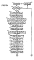
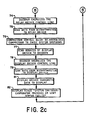
- FIGURE 2 is a flow chart illustrating the logic sequence of operations and decisions which occur in operating the diagnostic system.
- FIGURE 1 the air conditioning system disclosed in FIGURE 1 is a large commercial or industrial system of the type having a centrifugal liquid chiller.
- Centrifugal compressor 12 discharges compressed refrigerant which flows through condenser 13 where it condenses and cools by transfering heat to the water which circulates between the cooling tower (not shown) and the condenser. From the condenser 13 the refrigerant passes through the expansion device 14 and then through the evaporator 15 to the inlet of the centrifugal compressor.
- Liquid (specifically water in the illustrated emboidment) is received from the building (or other cooling load) over line 16 and flows through a heat exchange coil in the evaporator 15, after which it exits through line 17 for return to the building which may be remotely located from the evaporator.
- the liquid or water is chilled as it flows through the coil in evaporator 15, transferring heat to the refrigerant.
- the chilled water is employed to cool the building in any well-known manner.
- air handlers or fan coil units may be used in which fans blow room air over coils through which the chilled water flows.
- the inlet of compressor 12 usually comprises adjustable guide vanes or prerotation vanes (PRV) to regulate the quantity of refrigerant flowing through the compressor. The capacity of the compressor is adjusted by varying the position of the prerotation vanes.
- PRV prerotation vanes
- Temperature sensor 18 which may be a thermistor, is positioned to sense the temperature of the chilled water leaving the evaporator 15 and produces an electrical analog voltage signal which is proportional to and representative of the actual measured temperature.
- control apparatus (not shown), which operates in response to the temperature sensed by sensor 18, controls the prerotation vanes to regulate the capacity of the compressor 12 as necessary to maintain the leaving chilled water temperature (LCWT) at a desired setpoint.
- the control system for the compressor has not been shown in order to avoid unduly encumbering the application.
- Pressure sensor 19 which is provided to monitor the refrigerant pressure in the evaporator 15 to prevent freeze-up of the circulating chilled liquid, outputs an analog voltage representing the evaporator refrigerant pressure.
- the circuitry which is conventionally connected to sensors 18 and 19 to utilize the sensed data has not been shown in FIGURE 1 since such circuitry is not part of the invention.
- the outputs of sensors 18 and 19 have a predetermined known relationship relative to each other when the sensors are functioning properly, and this occurs regardless of the operating condition of the air conditioning system.
- microcomputer-based apparatus which operates in response to the outputs of sensors 18 and 19, determines whether the predetermined known relationship, or an impossible relationship, exists between those outputs. Finding an impossible state means that at least one of sensors 18 and 19 is defective and an appropriate warning message is visually displayed to operating personnel to facilitate repair or replacement of the malfunctioning sensor. In addition, the air conditioning system is shut down as a safety precaution.
- microcomputer 24 which may be of the type manufactured by Intel and designated by the number 8051. That particular microcomputer includes a ROM (read only memory) sufficient to permanently store the required program. All of the circuits controlled by microcomputer 24 are also of conventional construction and are commercially available.
- Multiplexer 27 is an integrated circuit chip and has the capability of simultaneously receiving analog voltage signals over several different input channels and outputting these signals one at a time to analog-to-digital (A/D) converter 28 under the control of decoder 29 and latch 31, which in turn are controlled by microcomputer 24. While multiplexer 27 is capable of handling a much larger number of inputs than the two needed to implement the invention, such a multiplexer would be needed to facilitate the monitoring and control of other parameters in the air conditioning system.
- RAM (random access memory) 32 is employed to store temperature information until it is needed.
- Display driver 34 when energized functions as a buffer and transmits data from the ROM in the microcomputer 24 to display 35 to provide a message to operating personnel. When relay driver 36 is operated the compressor control relay 37 is de-energized to disconnect the input power to the compressor motor, thereby shutting down the air conditioning system.
- microcomputer 24 may easily be programmed to control and monitor different functions and operating characteristics of the air conditioning system.
- the microcomputer may be programmed to control the compressor capacity, in response to the temperature sensed by sensor 18, to hold the leaving chilled water at a desired temperature setpoint.
- the information from sensor 18 representing the actual temperature of the leaving chilled water may be effectively compared with the desired setpoint information and from the comparison an appropriate control signal may be developed to adjust the prerotation vanes in centrifugal compressor 12 to the setting required to maintain the temperature of the leaving chilled water relatively constant and at the desired setpoint.
- FIGURE 2 depicts the portion of the microcomputer's program dealing with the process for detecting if sensors 18 and 19 are faulty.
- this program portion is a subroutine of the main program. Since the computing system is capable of monitoring and controlling several parameters in the air conditioning system, when all of the contemplated functions are included the complete program for microcomputer 24 will be substantially greater than that illustrated in FIGURE 2.
- decision block 42 determines whether the air conditioning system has been powered up and has been operating for at least ten minutes. This preset time period is necessary to allow the evaporator refrigerant pressure and the leaving chilled liquid temperature to stabilize. If the system has not been running for ten minutes the subroutine is bypassed and the main program is continued as indicated by block 43.
- microcomputer 24 transmits to decoder 29 (via the address bus) the address of multiplexer 27 (see operation block 44), whereupon the decoder energizes the control line to the multiplexer (block 45) to activate the multiplexer.
- the address of the leaving chilled water temperature (LCWT) input 46 to the multiplexer is then forwarded from microcomputer 24 and over the data/address bus to latch 31, as indicated by operation block 47, the latch retaining that address while at the same time transmitting it over the control bus to the multiplexer so that the analog voltage signal, appearing at input 46 and representing the leaving chilled water temperature, will be channeled to the output of the multiplexer, see block 48.
- LCWT leaving chilled water temperature
- the address of the A/D converter 28 is forwarded to decoder 29 which then (block 51) supplies an energizing signal over the control line to converter 28. Since latch 31 will be holding the LCWT input address, the output voltage from sensor 18 will be fed through the multiplexer to the input of the A/D converter and converted to a digital signal or binary number (block 52) representing the leaving chilled water temperature.
- the program then steps to block 53, in accordance with which the address of RAM 32 is transmitted to decoder 29, which thereupon energizes the control line to the RAM (block 54) in order that the LCWT binary number may be stored (block 55) in the RAM for later use.
- the address of the multiplexer is again sent to decoder 29 to effect energization by the decoder of the control line to the multiplexer (block 57).
- the address of the evaporator pressure input 58 is then transmitted from microcomputer 24 to latch 31 (block 59), which retains the address while sending it to the multiplexer (block 61).
- the address of the A/D converter is forwarded to the decoder, in response to which the decoder energizes the control line to the converter (block 63) so that the evaporator pressure output voltage from sensor 19 will be input to the converter and converted to a digital signal or binary number (block 64) representing the evaporator pressure.
- the evaporator pressure binary number is then inputted to the microcomputer (block 65), after which the microcomputer (see block 66), using a pressure versus temperature look-up conversion table for the refrigerant (typically R11) which is stored in the ROM, converts the binary number representing the evaporator refrigerant pressure to a binary number representing the equivalent evaporator refrigerant temperature. Thereafter, the microcomputer feeds the address of the RAM to the decoder (block 67) to effect energization of the control line to the RAM (block 68) so that the LCWT binary number may be supplied to the microcomputer (block 69).
- the microcomputer feeds the address of the RAM to the decoder (block 67) to effect energization of the control line to the RAM (block 68) so that the LCWT binary number may be supplied to the microcomputer (block 69).
- the step indicated by block 71 in the program is then executed by the microcomputer to subtract the equivalent evaporator refrigerant temperature from the leaving chilled water temperature. This is a binary subtraction of the two numbers representing the two temperatures and provides a resultant difference temperature ⁇ .
- the difference temperature ⁇ will always fall somewhere within a known temperature range. In the illustrated embodiment that range extends from about -2.5°F to about 25°F. Regardless of the operating condition of the air conditioning system, as long as the sensors are operating correctly the difference temperature ⁇ will lie between -2.5°F and 25°F.
- This computation is determined by the microcomputer in accordance with decision block 72. The YES exit of block 72 will therefore be followed, when the sensors are functioning properly, and the subroutine will be terminated and the main program will be continued (block 43).
Landscapes
- Engineering & Computer Science (AREA)
- Physics & Mathematics (AREA)
- Mechanical Engineering (AREA)
- Thermal Sciences (AREA)
- General Engineering & Computer Science (AREA)
- Air Conditioning Control Device (AREA)
Claims (7)
- Klimaanlage mit einem Flüssigkeitskühler bei der Kühlmittel durch einen Verdampfer (15) zu einem Kompressor (12) strömt, um umlaufende Flüssigkeit (bei 16,17) durch eine Wärmetauscherwicklung in dem Verdampfer zu kühlen, ein Temperatursensor (18) ist zum Erfassen der Temperatur für die aus dem Verdampfer austretende Flüssigkeit vorgesehen, und ein Diagnosesystem (27 bis 36) um einen fehlerhaften Sensor in dem System zu erfassen und das Mittel aufweist um von dem Ausgang des Temperatursensors (18) ein Flüssigkeitstemperatursignal zu entwickeln das die Temperatur der ausströmenden gekühlten Flüssigkeit repräsentiert, und eine Warneinrichtung (35) um eine Warnmeldung für Bedienungspersonal abzugeben wenn ein fehlerhafter Sensor erfaßt wird, dadurch gekennzeichnet, daß die Klimaanlage einen Drucksensor (19) umfaßt um den Druck des Kühlmittels in dem Verdampfer zu erfassen, und daß das Diagnosesystem Mittel umfaßt um von dem Ausgang des Drucksensors (19), während des Betriebs der Klimaanlage, ein Kühlflüssigkeitsdrucksignal zu entwickeln, das den Verdampferkühlflüssigkeitsdruck repräsentiert; eine Recheneinrichtung (24) um von dem Kühlmitteldrucksignal ein Signal zu bestimmen, welches zu der Verdampferkühlmitteltemperatur repräsentativ ist, wobei die Recheneinrichtung dazu geeignet ist eine Differenz zwischen dem die Verdampferkühlmitteltemperatur repräsentierenden Signal und dem Flüssigkeitstemperatursignal zu ermitteln und die Warneinrichtung zu aktivieren, wenn eine derart ermittelte Differenz außerhalb eines vorgegebenen Bereiches liegt, in dem die Differenz stets unabhängig von dem Betriebszustand des Systems liegt um dadurch anzuzeigen, daß der Ausgang eines der Sensoren (18, 19) einen Fehler aufweist und um dadurch anzuzeigen, daß der Sensor fehlerhaft ist; und eine durch die Recheneinrichtung (24) gesteuerte Einrichtung (37) um den Kompressor (12) der Klimaanlage als Sicherheitsmaßnahme abzuschalten wenn ein fehlerhafter Sensor festgestellt wird.
- Klimaanlage nach Anspruch 1, bei der die Warneinrichtung über eine optische Anzeige (35) anzeigt, daß ein fehlerhafter Sensor entdeckt wurde.
- Klimaanlage nach einem der vorhergehenden Ansprüche, bei der die Recheneinrichtung einen Mikrocomputer (24) umfaßt.
- Klimaanlage nach einem der vorhergehenden Ansprüche, bei der eine Einrichtung vorgesehen ist, um den Betrieb der Recheneinrichtung über eine vorgebbare Zeitspanne nach einem Leistungsanstieg der Klimaanlage auszusetzen damit sich der Verdampferkühlmitteldruck und die Temperatur der ausströmenden gekühlten Flüsssigkeit stabilisieren können.
- Klimaanlage nach einem der vorhergehenden Ansprüche, wobei über die Recheneinrichtung (24) von dem Kühlmitteldrucksignal die äquivalende Verdampferkühlflüssigkeitstemperatur ausgehend von dem Druck-Temperaturverhältnis des Kühlmittels berechnet werden kann.
- Klimaanlage nach einem der vorstehenden Ansprüche, wobei das Verdampferkühlmitteltemperatursignal und das Temperatursignal der ausströmenden gekühlten Flüssigkeit in der Recheneinrichtung in Form von Binärzahlen vorliegt und eine binäre Subtraktion dieser Zahlen eine resultierende Binärzahl ergibt die die Differenztemperatur repräsentiert.
- Klimaanlage nach einem der vorstehenden Ansprüche, bei der der vorgegebenen bekannte Temperaturbereich sich von etwa - 1,4 ° C bis etwa 14 ° C (etwa - 2,5 ° F bis etwa 25 ° F) erstreckt und die Differenztemperatur in jedem Betriebszustand der Klimaanlage in diesem Bereich fällt solange die Sensoren ordnungsgemäß funktionieren.
Applications Claiming Priority (2)
| Application Number | Priority Date | Filing Date | Title |
|---|---|---|---|
| US777383 | 1985-09-18 | ||
| US06/777,383 US4660386A (en) | 1985-09-18 | 1985-09-18 | Diagnostic system for detecting faulty sensors in liquid chiller air conditioning system |
Publications (3)
| Publication Number | Publication Date |
|---|---|
| EP0216547A2 EP0216547A2 (de) | 1987-04-01 |
| EP0216547A3 EP0216547A3 (en) | 1988-04-27 |
| EP0216547B1 true EP0216547B1 (de) | 1991-05-08 |
Family
ID=25110104
Family Applications (1)
| Application Number | Title | Priority Date | Filing Date |
|---|---|---|---|
| EP86306851A Expired - Lifetime EP0216547B1 (de) | 1985-09-18 | 1986-09-04 | Diagnostisches System zur Ermittlung von fehlerhaften Sensoren in einer mit einem Flüssigkeitskühler versehenen Klimaanlage |
Country Status (8)
| Country | Link |
|---|---|
| US (1) | US4660386A (de) |
| EP (1) | EP0216547B1 (de) |
| JP (1) | JP2516600B2 (de) |
| KR (1) | KR950007283B1 (de) |
| AU (1) | AU581152B2 (de) |
| CA (1) | CA1267461A (de) |
| DE (1) | DE3679134D1 (de) |
| MX (1) | MX167150B (de) |
Families Citing this family (69)
| Publication number | Priority date | Publication date | Assignee | Title |
|---|---|---|---|---|
| US4653280A (en) * | 1985-09-18 | 1987-03-31 | Hansen John C | Diagnostic system for detecting faulty sensors in a refrigeration system |
| JP2701911B2 (ja) * | 1989-01-20 | 1998-01-21 | 株式会社日立製作所 | 冷却設備の制御方式 |
| US5235527A (en) * | 1990-02-09 | 1993-08-10 | Toyota Jidosha Kabushiki Kaisha | Method for diagnosing abnormality of sensor |
| GB9008788D0 (en) * | 1990-04-19 | 1990-06-13 | Whitbread & Co Plc | Diagnostic equipment |
| US5276630A (en) * | 1990-07-23 | 1994-01-04 | American Standard Inc. | Self configuring controller |
| US5083438A (en) * | 1991-03-01 | 1992-01-28 | Mcmullin Larry D | Chiller monitoring system |
| US5209400A (en) * | 1991-03-07 | 1993-05-11 | John M. Winslow | Portable calculator for refrigeration heating and air conditioning equipment service |
| US5623426A (en) * | 1994-02-23 | 1997-04-22 | Sanyo Electric Co., Ltd. | Failure diagnosing system for absorption chillers |
| US5423188A (en) * | 1994-03-17 | 1995-06-13 | Carrier Corporation | Process for detecting out-of-range thermistor |
| US6047557A (en) * | 1995-06-07 | 2000-04-11 | Copeland Corporation | Adaptive control for a refrigeration system using pulse width modulated duty cycle scroll compressor |
| KR100208345B1 (ko) * | 1996-04-02 | 1999-07-15 | 윤종용 | 냉장고의 온도제어방법 및 온도제어장치 |
| US5791155A (en) * | 1997-06-06 | 1998-08-11 | Carrier Corporation | System for monitoring expansion valve |
| US5860286A (en) * | 1997-06-06 | 1999-01-19 | Carrier Corporation | System monitoring refrigeration charge |
| US5860285A (en) * | 1997-06-06 | 1999-01-19 | Carrier Corporation | System for monitoring outdoor heat exchanger coil |
| US6091324A (en) * | 1998-11-13 | 2000-07-18 | Ford Motor Company | Comparing sensor outputs to distinguish between sensor faults and extreme temperature conditions |
| US6505475B1 (en) | 1999-08-20 | 2003-01-14 | Hudson Technologies Inc. | Method and apparatus for measuring and improving efficiency in refrigeration systems |
| PT1254146E (pt) * | 1999-12-16 | 2005-10-31 | Teva Pharma | Processos de preparacao de polimeros de claritromicina e novo polimorfo iv |
| US7047753B2 (en) * | 2000-03-14 | 2006-05-23 | Hussmann Corporation | Refrigeration system and method of operating the same |
| US6357241B1 (en) * | 2000-12-22 | 2002-03-19 | Carrier Corporation | Method of controlling refrigerant cycle with sealed suction pressure sensor |
| US20020082884A1 (en) * | 2000-12-22 | 2002-06-27 | Moroney Brady J. | Manufacturing and testing communications system |
| US6892546B2 (en) | 2001-05-03 | 2005-05-17 | Emerson Retail Services, Inc. | System for remote refrigeration monitoring and diagnostics |
| US6668240B2 (en) * | 2001-05-03 | 2003-12-23 | Emerson Retail Services Inc. | Food quality and safety model for refrigerated food |
| US6889173B2 (en) * | 2002-10-31 | 2005-05-03 | Emerson Retail Services Inc. | System for monitoring optimal equipment operating parameters |
| WO2005022049A2 (en) * | 2003-08-25 | 2005-03-10 | Computer Process Controls, Inc. | Refrigeration control system |
| US20070150305A1 (en) * | 2004-02-18 | 2007-06-28 | Klaus Abraham-Fuchs | Method for selecting a potential participant for a medical study on the basis of a selection criterion |
| US7412842B2 (en) | 2004-04-27 | 2008-08-19 | Emerson Climate Technologies, Inc. | Compressor diagnostic and protection system |
| JP4485863B2 (ja) * | 2004-07-09 | 2010-06-23 | 株式会社神戸製鋼所 | 圧縮機 |
| US7275377B2 (en) | 2004-08-11 | 2007-10-02 | Lawrence Kates | Method and apparatus for monitoring refrigerant-cycle systems |
| ATE553422T1 (de) * | 2005-02-21 | 2012-04-15 | Computer Process Controls Inc | Kontroll- und beobachtungssystem für unternehmen |
| US7665315B2 (en) * | 2005-10-21 | 2010-02-23 | Emerson Retail Services, Inc. | Proofing a refrigeration system operating state |
| US7752854B2 (en) * | 2005-10-21 | 2010-07-13 | Emerson Retail Services, Inc. | Monitoring a condenser in a refrigeration system |
| US7596959B2 (en) | 2005-10-21 | 2009-10-06 | Emerson Retail Services, Inc. | Monitoring compressor performance in a refrigeration system |
| US20070089436A1 (en) * | 2005-10-21 | 2007-04-26 | Abtar Singh | Monitoring refrigerant in a refrigeration system |
| US7594407B2 (en) | 2005-10-21 | 2009-09-29 | Emerson Climate Technologies, Inc. | Monitoring refrigerant in a refrigeration system |
| US7752853B2 (en) | 2005-10-21 | 2010-07-13 | Emerson Retail Services, Inc. | Monitoring refrigerant in a refrigeration system |
| US20070089435A1 (en) * | 2005-10-21 | 2007-04-26 | Abtar Singh | Predicting maintenance in a refrigeration system |
| US20070093732A1 (en) * | 2005-10-26 | 2007-04-26 | David Venturi | Vibroacoustic sound therapeutic system and method |
| JP2009523647A (ja) * | 2006-01-20 | 2009-06-25 | コンティネンタル・テーベス・アクチエンゲゼルシヤフト・ウント・コンパニー・オッフェネ・ハンデルスゲゼルシヤフト | 真空式制動倍力装置と当該装置を操作する方法 |
| US8590325B2 (en) | 2006-07-19 | 2013-11-26 | Emerson Climate Technologies, Inc. | Protection and diagnostic module for a refrigeration system |
| US20080216494A1 (en) | 2006-09-07 | 2008-09-11 | Pham Hung M | Compressor data module |
| US20090037142A1 (en) | 2007-07-30 | 2009-02-05 | Lawrence Kates | Portable method and apparatus for monitoring refrigerant-cycle systems |
| WO2009038624A1 (en) * | 2007-09-19 | 2009-03-26 | Emerson Climate Technologies, Inc. | Refrigeration monitoring system and method |
| US8393169B2 (en) * | 2007-09-19 | 2013-03-12 | Emerson Climate Technologies, Inc. | Refrigeration monitoring system and method |
| US8160827B2 (en) | 2007-11-02 | 2012-04-17 | Emerson Climate Technologies, Inc. | Compressor sensor module |
| US9140728B2 (en) * | 2007-11-02 | 2015-09-22 | Emerson Climate Technologies, Inc. | Compressor sensor module |
| WO2010138831A2 (en) | 2009-05-29 | 2010-12-02 | Emerson Retail Services, Inc. | System and method for monitoring and evaluating equipment operating parameter modifications |
| KR20110074109A (ko) * | 2009-12-24 | 2011-06-30 | 엘지전자 주식회사 | 공기조화기 및 공기조화기의 제어방법 |
| US20120031985A1 (en) * | 2010-08-09 | 2012-02-09 | Terry Lien Do | Fault tolerant appliance |
| CA2828740C (en) | 2011-02-28 | 2016-07-05 | Emerson Electric Co. | Residential solutions hvac monitoring and diagnosis |
| US9074801B2 (en) * | 2011-11-14 | 2015-07-07 | Bosch Automotive Services Solutions INC. | Apparatus and method for identifying and operating air purge in safe mode and having a dip tube |
| US8964338B2 (en) | 2012-01-11 | 2015-02-24 | Emerson Climate Technologies, Inc. | System and method for compressor motor protection |
| US9480177B2 (en) | 2012-07-27 | 2016-10-25 | Emerson Climate Technologies, Inc. | Compressor protection module |
| US9310439B2 (en) | 2012-09-25 | 2016-04-12 | Emerson Climate Technologies, Inc. | Compressor having a control and diagnostic module |
| US9829230B2 (en) * | 2013-02-28 | 2017-11-28 | Mitsubishi Electric Corporation | Air conditioning apparatus |
| US9551504B2 (en) | 2013-03-15 | 2017-01-24 | Emerson Electric Co. | HVAC system remote monitoring and diagnosis |
| US9803902B2 (en) | 2013-03-15 | 2017-10-31 | Emerson Climate Technologies, Inc. | System for refrigerant charge verification using two condenser coil temperatures |
| CA2904734C (en) | 2013-03-15 | 2018-01-02 | Emerson Electric Co. | Hvac system remote monitoring and diagnosis |
| AU2014248049B2 (en) | 2013-04-05 | 2018-06-07 | Emerson Climate Technologies, Inc. | Heat-pump system with refrigerant charge diagnostics |
| EP3770518A3 (de) * | 2013-12-20 | 2021-06-23 | Belimo Holding AG | Ventilsteuerung in einem hlk-system mit sensoren |
| US12078378B1 (en) | 2016-09-02 | 2024-09-03 | John R. Williams | Continuously variable chiller and control systems, methods, and apparatuses |
| US10906374B2 (en) * | 2018-12-03 | 2021-02-02 | Ford Global Technologies, Llc | A/C compressor control using refrigerant pressure |
| US11467571B2 (en) * | 2019-03-06 | 2022-10-11 | Johnson Controls Tyco IP Holdings LLP | Systems and methods for building management system sensor diagnostics and management |
| US11493221B2 (en) | 2019-07-15 | 2022-11-08 | Johnson Controls Tyco IP Holdings LLP | Alternative defrost mode of HVAC system |
| US12050041B2 (en) | 2019-07-15 | 2024-07-30 | Tyco Fire & Security Gmbh | Alternative defrost mode of HVAC system |
| US12380517B2 (en) | 2020-08-18 | 2025-08-05 | Tyco Fire & Security Gmbh | Building system with a recommendation interface |
| US20220058556A1 (en) | 2020-08-18 | 2022-02-24 | Johnson Controls Tyco IP Holdings LLP | Building system with building health analysis |
| CN112665234B (zh) * | 2020-12-10 | 2022-02-15 | 珠海格力电器股份有限公司 | 蒸发器除霜控制方法、装置及热泵机组 |
| US12282008B2 (en) | 2021-07-14 | 2025-04-22 | Carrier Corporation | Methods of reducing the occurance of false positives in gas detectors |
| US12188670B2 (en) | 2021-10-13 | 2025-01-07 | Tyco Fire & Security Gmbh | Building system for building equipment with occupant feedback based verification |
Citations (1)
| Publication number | Priority date | Publication date | Assignee | Title |
|---|---|---|---|---|
| US3232519A (en) * | 1963-05-07 | 1966-02-01 | Vilter Manufacturing Corp | Compressor protection system |
Family Cites Families (15)
| Publication number | Priority date | Publication date | Assignee | Title |
|---|---|---|---|---|
| US3707851A (en) * | 1970-10-28 | 1973-01-02 | Mach Ice Co | Refrigeration system efficiency monitor |
| US4060997A (en) * | 1976-03-31 | 1977-12-06 | Application Engineering Corporation | Water chiller control |
| US4122720A (en) * | 1977-04-07 | 1978-10-31 | Alnor Instrument Company | Diesel engine exhaust temperature monitor |
| US4249238A (en) * | 1978-05-24 | 1981-02-03 | The United States Of America As Represented By The Administrator Of The National Aeronautics And Space Administration | Apparatus for sensor failure detection and correction in a gas turbine engine control system |
| JPS55164793A (en) * | 1979-06-07 | 1980-12-22 | Toyoda Autom Loom Works Ltd | Protecting device for refrigerant compressor |
| US4282719A (en) * | 1979-09-12 | 1981-08-11 | Borg-Warner Corporation | Control system for regulating large capacity rotating machinery |
| US4337516A (en) * | 1980-06-26 | 1982-06-29 | United Technologies Corporation | Sensor fault detection by activity monitoring |
| US4381549A (en) * | 1980-10-14 | 1983-04-26 | Trane Cac, Inc. | Automatic fault diagnostic apparatus for a heat pump air conditioning system |
| US4325223A (en) * | 1981-03-16 | 1982-04-20 | Cantley Robert J | Energy management system for refrigeration systems |
| JPS6027905B2 (ja) * | 1981-04-03 | 1985-07-02 | トヨタ自動車株式会社 | 空調制御方法 |
| US4448033A (en) * | 1982-03-29 | 1984-05-15 | Carrier Corporation | Thermostat self-test apparatus and method |
| US4538419A (en) * | 1984-04-06 | 1985-09-03 | Carrier Corporation | Refrigeration unit controls |
| US4535598A (en) * | 1984-05-14 | 1985-08-20 | Carrier Corporation | Method and control system for verifying sensor operation in a refrigeration system |
| US4546618A (en) * | 1984-09-20 | 1985-10-15 | Borg-Warner Corporation | Capacity control systems for inverter-driven centrifugal compressor based water chillers |
| US4653280A (en) * | 1985-09-18 | 1987-03-31 | Hansen John C | Diagnostic system for detecting faulty sensors in a refrigeration system |
-
1985
- 1985-09-18 US US06/777,383 patent/US4660386A/en not_active Expired - Lifetime
-
1986
- 1986-09-04 DE DE8686306851T patent/DE3679134D1/de not_active Expired - Fee Related
- 1986-09-04 EP EP86306851A patent/EP0216547B1/de not_active Expired - Lifetime
- 1986-09-10 MX MX003700A patent/MX167150B/es unknown
- 1986-09-16 AU AU62710/86A patent/AU581152B2/en not_active Ceased
- 1986-09-16 KR KR1019860007788A patent/KR950007283B1/ko not_active Expired - Fee Related
- 1986-09-16 JP JP61217858A patent/JP2516600B2/ja not_active Expired - Fee Related
- 1986-09-18 CA CA000518539A patent/CA1267461A/en not_active Expired - Lifetime
Patent Citations (1)
| Publication number | Priority date | Publication date | Assignee | Title |
|---|---|---|---|---|
| US3232519A (en) * | 1963-05-07 | 1966-02-01 | Vilter Manufacturing Corp | Compressor protection system |
Also Published As
| Publication number | Publication date |
|---|---|
| AU581152B2 (en) | 1989-02-09 |
| DE3679134D1 (de) | 1991-06-13 |
| AU6271086A (en) | 1987-03-19 |
| KR950007283B1 (ko) | 1995-07-07 |
| EP0216547A3 (en) | 1988-04-27 |
| EP0216547A2 (de) | 1987-04-01 |
| JP2516600B2 (ja) | 1996-07-24 |
| MX167150B (es) | 1993-03-08 |
| US4660386A (en) | 1987-04-28 |
| KR870003451A (ko) | 1987-04-17 |
| CA1267461A (en) | 1990-04-03 |
| JPS62112975A (ja) | 1987-05-23 |
Similar Documents
| Publication | Publication Date | Title |
|---|---|---|
| US4660386A (en) | Diagnostic system for detecting faulty sensors in liquid chiller air conditioning system | |
| US4653280A (en) | Diagnostic system for detecting faulty sensors in a refrigeration system | |
| JP3080978B2 (ja) | 輸送機関用冷凍システムのモニター方法および装置 | |
| US5460006A (en) | Monitoring system for food storage device | |
| US10588246B2 (en) | Systems and associated methods for controllably cooling computer components | |
| US4262736A (en) | Apparatus for heat pump malfunction detection | |
| US4663725A (en) | Microprocessor based control system and method providing better performance and better operation of a shipping container refrigeration system | |
| EP0158581B1 (de) | Verfahren und Regelvorrichtung zum Schützen eines Verdampfers in einem Kühlsystem gegen Zufrieren | |
| US11725837B2 (en) | Detection of a reversing valve fault | |
| CA3087774C (en) | DETECTION OF ANOMALIES ON THE REFRIGERATOR SIDE | |
| US5752654A (en) | Method and apparatus for providing supplemental heating | |
| GB2260816A (en) | Monitoring fluid quantities | |
| US6342840B1 (en) | Service controller for temperature-controlled appliances | |
| US20250146743A1 (en) | A method for generating early temperature warning in a vapour compression system | |
| JPH10197031A (ja) | 空気調和装置の故障検出装置 | |
| JPH05240570A (ja) | 温度制御装置の異常警告装置 | |
| JP2641347B2 (ja) | 冷却装置 | |
| JP2532937B2 (ja) | 冷凍装置の冷媒回路異常管理システム | |
| KR0164988B1 (ko) | 냉장고의 온도제어방법 및 냉장고의 온도제어장치 | |
| JPH0526446Y2 (de) | ||
| JP2651392B2 (ja) | 空気調和機の遠隔監視システム | |
| JPS58106343A (ja) | 換気空調補機冷却系の主冷水制御装置 | |
| JPH0560410A (ja) | 輸送用冷凍装置 | |
| JPS58119003A (ja) | 運転台数制御装置 | |
| KR0130415B1 (ko) | 냉동기용 제어장치 |
Legal Events
| Date | Code | Title | Description |
|---|---|---|---|
| PUAI | Public reference made under article 153(3) epc to a published international application that has entered the european phase |
Free format text: ORIGINAL CODE: 0009012 |
|
| AK | Designated contracting states |
Kind code of ref document: A2 Designated state(s): DE FR GB |
|
| PUAL | Search report despatched |
Free format text: ORIGINAL CODE: 0009013 |
|
| AK | Designated contracting states |
Kind code of ref document: A3 Designated state(s): DE FR GB |
|
| 17P | Request for examination filed |
Effective date: 19880909 |
|
| 17Q | First examination report despatched |
Effective date: 19890301 |
|
| GRAA | (expected) grant |
Free format text: ORIGINAL CODE: 0009210 |
|
| AK | Designated contracting states |
Kind code of ref document: B1 Designated state(s): DE FR GB |
|
| REF | Corresponds to: |
Ref document number: 3679134 Country of ref document: DE Date of ref document: 19910613 |
|
| EN | Fr: translation not filed | ||
| ET | Fr: translation filed |
Free format text: BO 39/91 PAGE 199: LIRE 0216547 AU LIEU DE 0316547 |
|
| PLBE | No opposition filed within time limit |
Free format text: ORIGINAL CODE: 0009261 |
|
| STAA | Information on the status of an ep patent application or granted ep patent |
Free format text: STATUS: NO OPPOSITION FILED WITHIN TIME LIMIT |
|
| 26N | No opposition filed | ||
| REG | Reference to a national code |
Ref country code: GB Ref legal event code: IF02 |
|
| PGFP | Annual fee paid to national office [announced via postgrant information from national office to epo] |
Ref country code: GB Payment date: 20030826 Year of fee payment: 18 Ref country code: FR Payment date: 20030826 Year of fee payment: 18 |
|
| PGFP | Annual fee paid to national office [announced via postgrant information from national office to epo] |
Ref country code: DE Payment date: 20030908 Year of fee payment: 18 |
|
| PG25 | Lapsed in a contracting state [announced via postgrant information from national office to epo] |
Ref country code: GB Free format text: LAPSE BECAUSE OF NON-PAYMENT OF DUE FEES Effective date: 20040904 |
|
| PG25 | Lapsed in a contracting state [announced via postgrant information from national office to epo] |
Ref country code: DE Free format text: LAPSE BECAUSE OF NON-PAYMENT OF DUE FEES Effective date: 20050401 |
|
| GBPC | Gb: european patent ceased through non-payment of renewal fee |
Effective date: 20040904 |
|
| PG25 | Lapsed in a contracting state [announced via postgrant information from national office to epo] |
Ref country code: FR Free format text: LAPSE BECAUSE OF NON-PAYMENT OF DUE FEES Effective date: 20050531 |
|
| REG | Reference to a national code |
Ref country code: FR Ref legal event code: ST |