EP0218042A2 - Commutateur de proximité électronique dépendant d'un champ magnétique - Google Patents
Commutateur de proximité électronique dépendant d'un champ magnétique Download PDFInfo
- Publication number
- EP0218042A2 EP0218042A2 EP86111035A EP86111035A EP0218042A2 EP 0218042 A2 EP0218042 A2 EP 0218042A2 EP 86111035 A EP86111035 A EP 86111035A EP 86111035 A EP86111035 A EP 86111035A EP 0218042 A2 EP0218042 A2 EP 0218042A2
- Authority
- EP
- European Patent Office
- Prior art keywords
- coil
- switch according
- proximity switch
- torus
- arc piece
- Prior art date
- Legal status (The legal status is an assumption and is not a legal conclusion. Google has not performed a legal analysis and makes no representation as to the accuracy of the status listed.)
- Granted
Links
Images
Classifications
-
- H—ELECTRICITY
- H03—ELECTRONIC CIRCUITRY
- H03K—PULSE TECHNIQUE
- H03K17/00—Electronic switching or gating, i.e. not by contact-making and –breaking
- H03K17/94—Electronic switching or gating, i.e. not by contact-making and –breaking characterised by the way in which the control signals are generated
- H03K17/945—Proximity switches
- H03K17/95—Proximity switches using a magnetic detector
- H03K17/952—Proximity switches using a magnetic detector using inductive coils
- H03K17/9537—Proximity switches using a magnetic detector using inductive coils in a resonant circuit
- H03K17/9542—Proximity switches using a magnetic detector using inductive coils in a resonant circuit forming part of an oscillator
- H03K17/9547—Proximity switches using a magnetic detector using inductive coils in a resonant circuit forming part of an oscillator with variable amplitude
-
- H—ELECTRICITY
- H03—ELECTRONIC CIRCUITRY
- H03K—PULSE TECHNIQUE
- H03K17/00—Electronic switching or gating, i.e. not by contact-making and –breaking
- H03K17/94—Electronic switching or gating, i.e. not by contact-making and –breaking characterised by the way in which the control signals are generated
- H03K17/945—Proximity switches
- H03K17/95—Proximity switches using a magnetic detector
- H03K17/9505—Constructional details
Definitions
- the invention relates to a magnetic field-dependent, electronic proximity switch, which is actuated by an approaching magnetic trigger, with an RF resonant circuit which can be influenced by the trigger, of an oscillator circuit, the coil arrangement of which has a resonant circuit coil and a coupling coil and is associated with a magnetic body which is determined from a specific one Magnetic field strength can be driven into magnetic saturation by the external magnetic field of the trigger while damping the resonant circuit.
- a proximity switch with an oscillator circuit in which a permeable metal plate is arranged between the oscillating circuit coil and the feedback coil. Through this metal plate the voice coil is largely shielded from the coupling coil, so that only strongly damped vibrations occur. By approaching a permanent magnetic release, the metal plate there can be driven to saturation, whereby its shielding effect is abruptly reduced and thus a clear damping of the resonant circuit results. This effect is used to operate an electronic switch. Since the resonant circuit is heavily damped in the basic state, i.e. it does not provide an output signal, errors in the electronic circuit which always lead to the signal being torn off but not to light up cannot be erroneously converted into a switching signal.
- the known proximity switch however, has a low sensitivity in relation to its size, which is why it does not have to pass through non-permeable metal walls, for example with a small design - for example with only one cubic centimeter of space.
- B. can be triggered from aluminum or austenitic steel.
- the invention has for its object to provide a generic proximity switch which has a high sensitivity with a small size.
- the magnetizable body consists of an amorphous or predominantly amorphous metal strip and that the resonant circuit coil and the coupling coil sit on a common winding body.
- Amorphous metal which is also referred to in the American literature as metallic glass and which is sold in Germany under the protected trademark "Vitrovac”, is a material that has a high permeability, but its electrical conductivity compared to transformer or dynamo sheets is low.
- the resonant circuit is strongly damped in the basic state and is abruptly excited to strong vibrations by an approaching magnetic release, with a very high sensitivity being given even with a small size.
- the oscillating circuit coil and the coupling coil sit on a common winding body, the magnetic release does not influence the coupling behavior between the two coils, or does so only to an insignificant extent.
- the decisive factor - despite the relatively low electrical conductivity of the amorphous metal strip - is the induction of very strong eddy currents in the amorphous metal strip. Due to its high permeability, the metal strip seems to bind the RF resonant circuit field so closely to itself that large eddy current losses occur. At Approach of a trigger is also attracted to the magnetic field in a special way by the amorphous metal strip, so that it is quickly driven to saturation.
- the amorphous metal strip can be designed as a straight, thin strip which is arranged on the axis of the coil arrangement and passes through the coil torus.
- the amorphous metal band can have the shape of a self-contained ring or oval, the ring or oval passing through the coil axis and the Coil torus wraps around.
- the problem with conventional proximity switches, for example reed contacts, is that multiple trips can occur when the trigger is moved along the proximity switch.
- the formation of the amorphous metal strip in the form of a self-contained ring or oval only results in a single switching operation when the trigger is passed. With such a transverse movement of the release, the switching zone is otherwise narrowly limited, so that a very precise position detection of the release is ensured.
- the characteristic data of the proximity switch can be influenced within certain limits by a simple deformation of the annular metal band. It proves to be advantageous that the amorphous metal strip does not undergo any change in its magnetic property due to bending or the like.
- two or more self-contained, ring-shaped or oval metal strips can be provided, which are distributed along the coil torus.
- the characteristics of a proximity switch can also be influenced by the arrangement of several metal band rings. It is particularly advantageous to enlarge the Response range for a movement of the trigger towards the proximity switch, while the response zone remains very narrow with respect to a transverse movement of the trigger.
- the metal strip can have a thickness between 15 to 50 ⁇ , preferably 30 ⁇ , and a width of two to three millimeters. Furthermore, according to the invention, the ring diameter can be on the order of two to ten millimeters. Even with these small sizes, very high response sensitivities can be achieved.
- the amorphous metal band is designed as a U-shaped or C-shaped arch piece, the opening of which is on the response side of the proximity switch.
- the opening of which is on the response side of the proximity switch.
- Such a proximity switch can be used for a wide variety of sensitivity ranges and eliminates the need for various types.
- the back of the arc piece advantageously lies in the coil torus, which results in an exactly symmetrical response zone.
- the width of the curved piece opening can be approximately equal to or smaller than the axial Dimension of the coil torus.
- a particularly advantageous embodiment in terms of production technology results from an annular configuration of the arc piece and with an annular opening width that is approximately equal to or smaller than the radius of the arc piece. With a radius of approximately 3 millimeters of the ring-shaped arc piece, the opening width is approximately 2.5 millimeters.
- the back of the arc piece lies on the end face of the coil torus opposite the response side and that the arc piece engages around a half of the torus with its side legs.
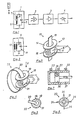
- the oscillator part 1 shows in a block diagram representation an electronic proximity switch with an oscillator part 1, an evaluation stage 2, a switching amplifier 3 and a switching element 4, the latter having a switching transistor or preferably a thyristor.
- the oscillator part 1 comprises an RF resonant circuit 5 with an oscillating circuit coil 6 which has a tap 7. Part of the resonant circuit coil 6 thus receives the function of a coupling coil 8, with which the oscillator part 1 z. B. can be operated in the so-called Hartley circuit.
- an oscillator part 9 can also be used, in which the oscillating circuit coil 10 of an HF oscillating circuit 11 is assigned a coupling coil 12, so that the oscillating part 9, for. B. can be operated in the so-called Meissner circuit.
- FIG. 3 shows a coil arrangement 13 with an oscillating circuit coil 6, which has a tap 7 in accordance with the exemplary embodiment according to FIG. 1.
- the resonant circuit coil 6 and the winding part acting as a coupling coil 8 are seated on a common winding body 14.
- An amorphous metal strip 15 is arranged on the axis of the coil arrangement 13, which is designed as a straight, thin strip and axially penetrates the coil ring or torus 16.
- the coil assembly 13 and the amorphous metal strip 15 together form a sensor head 17 of a proximity switch with high sensitivity.
- FIG. 4 shows a coil arrangement 18 with a resonant circuit coil 10 and a coupling coil 12 corresponding to FIG. 2, which are wound on a common winding body 19 and thus have a close inductive coupling.
- the coil arrangement 18 is assigned an amorphous metal strip 20 in the form of a self-contained ring which passes through the coil axis and wraps around the coil torus 21.
- the ring-shaped metal band 20 can be produced, for example, from a piece of strip, the ends of which are connected to one another in a magnetically conductive manner by spot welding.
- the coil arrangement 18 and the metal strip 20 together form a sensor head 22.
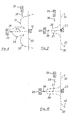
- the coil arrangement 13 according to FIG. 3 can also be used in connection with an annular metal strip 20 according to FIG. 4 or the coil arrangement 18 according to FIG. 4 in cooperation with a straight line Metal strip 15 according to FIG. 3.
- FIG. 6 shows a sensor head 23 with a coil arrangement 18 according to FIGS. 4 and 5 and a plurality of annular metal strips 24 which are distributed along the coil torus 21.
- the metal strip has a thickness between 15 and 50 ⁇ , preferably 30 ⁇ , and a width of one to three millimeters - if there are several Metal strips 24 also of one millimeter.
- the ring diameter is on the order of two to ten millimeters.
- a proximity switch with a sensor head 13 with a straight, amorphous metal strip 15 is particularly suitable for cases in which a high switching distance is to be achieved.
- a permanent magnetic release 25 - or an electromagnet - is frontal according to arrow 26, d. H. parallel to the sensor axis 27, brought up to the sensor head 13, a switching operation occurring when entering a response zone 28 shown in broken lines.
- a proximity switch with a sensor head 22 which is equipped with an annular metal band 20.
- Such a proximity switch only has a narrow, lance-shaped response zone 33 directly in front of the sensor head 22, while the secondary response zones 34, 35 lie almost completely behind the plane 30 of the sensor head 22.
- proximity switches with sensor heads 22 are particularly suitable for the position detection of pistons 36 (cf. FIG. 7).
- a plurality of sensor heads 22 can be arranged on the wall of a metallic, non-permeable cylinder 37, which detect the position of the trigger 25 attached to the piston 36. Since the distance between the sensor head 22 and the trigger 25 can be very small, the sensor heads 22 can also be flush with the cylinder 37 if necessary.
- FIG. 10 finally illustrates the area of application of a proximity switch with a sensor head 23 which has a plurality of annular metal strips 24.
- the use of the sensor head 23 creates a central, lance-shaped response zone 38, which is enlarged in the direction of the sensor axis 27 compared to the exemplary embodiment according to FIG. 9.
- the lateral response zones 39, 40 are nevertheless completely behind the sensor level 30, so that the sensor head 23 is suitable for all approaches of the trigger 25 in the same way.
- a shorter response distance of the order of magnitude of one centimeter or less is sufficient even when approaching parallel to the sensor axis 27, so that a sensor head 22 with only one annular metal band 20 can be used universally here.
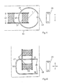
- FIG. 11 shows a preferred embodiment, in which the amorphous metal strip is designed as a C-shaped arc piece 41, which is bent in a ring shape and whose opening 42 lies on the response side 43 of the proximity switch.
- the coil and the arc piece 41 can be cast in resin to stabilize the position.
- the dashed line 44 indicates the outer contours of the sensor head of the proximity switch.
- the back 45 of the arc piece 41 lies in the opening of the coil torus 21, the width of the arc piece opening 42 being somewhat smaller than the axial one Dimension 46 of the coil torus 21 is. 11 can be built very small. With a diameter r of 3 millimeters of the annular arc piece 41, the width of the opening 42 is about 2.5 millimeters.
- the amorphous metal strip is designed as a U-shaped curved piece 47, the opening 48 of which is directed toward the response side 49 provided here laterally on the sensor head.
- the back 50 of the arc piece 47 lies on the front side of the coil torus 21 opposite the response side 49, and the arc piece 47 engages with its two side legs 51, 52 a torus half 53.
- the narrow response zone 38 illustrated in FIG. 10 results in a particularly concise manner, which in the exemplary embodiments according to FIGS. 11 and 12 can reach a width of over 30 millimeters.
- the secondary response zones 39, 40 lie clearly behind the sensor level 30, so that the problems of multiple triggering are reliably avoided.
Landscapes
- Switches That Are Operated By Magnetic Or Electric Fields (AREA)
Priority Applications (1)
| Application Number | Priority Date | Filing Date | Title |
|---|---|---|---|
| AT86111035T ATE49327T1 (de) | 1985-10-02 | 1986-08-09 | Magnetfeldabhaengiger, elektronischer annaeherungsschalter. |
Applications Claiming Priority (4)
| Application Number | Priority Date | Filing Date | Title |
|---|---|---|---|
| DE3535123 | 1985-10-02 | ||
| DE3535123 | 1985-10-02 | ||
| DE3544809 | 1985-12-18 | ||
| DE19853544809 DE3544809A1 (de) | 1985-10-02 | 1985-12-18 | Magnetfeldabhaengiger, elektronischer annaeherungsschalter |
Publications (4)
| Publication Number | Publication Date |
|---|---|
| EP0218042A2 true EP0218042A2 (fr) | 1987-04-15 |
| EP0218042A3 EP0218042A3 (en) | 1988-01-27 |
| EP0218042B1 EP0218042B1 (fr) | 1990-01-03 |
| EP0218042B2 EP0218042B2 (fr) | 1996-05-15 |
Family
ID=25836612
Family Applications (1)
| Application Number | Title | Priority Date | Filing Date |
|---|---|---|---|
| EP19860111035 Expired - Lifetime EP0218042B2 (fr) | 1985-10-02 | 1986-08-09 | Commutateur de proximité électronique dépendant d'un champ magnétique |
Country Status (3)
| Country | Link |
|---|---|
| US (1) | US4719362A (fr) |
| EP (1) | EP0218042B2 (fr) |
| DE (2) | DE3544809A1 (fr) |
Cited By (4)
| Publication number | Priority date | Publication date | Assignee | Title |
|---|---|---|---|---|
| DE4003426A1 (de) * | 1989-11-15 | 1991-05-16 | Turck Werner Kg | Magnetfeldabhaengiger elektronischer annaeherungsschalter |
| FR2658014A1 (fr) * | 1990-02-06 | 1991-08-09 | Turck Werner Kg | Interrupteur de proximite electronique par variation de champ magnetique. |
| EP0503340A1 (fr) * | 1991-03-08 | 1992-09-16 | Werner Turck GmbH & Co. KG | Commutateur de proximité inductif dépendant du champ magnétique |
| EP0635341A1 (fr) * | 1993-07-15 | 1995-01-25 | Gec Avery Limited | Dispositif de sécurité pour une machine électrique à découper en tranches |
Families Citing this family (25)
| Publication number | Priority date | Publication date | Assignee | Title |
|---|---|---|---|---|
| DE3632624C1 (de) * | 1986-09-25 | 1988-03-10 | Balluff Gebhard Feinmech | Stoerfeldunempfindlicher Naeherungsschalter |
| CH672383A5 (fr) * | 1986-10-29 | 1989-11-15 | Baumer Electric Ag | |
| DE3704893A1 (de) * | 1987-02-17 | 1988-08-25 | Turck Werner Kg | Anordnung fuer naeherungsschalter zum schutz gegen signalverfaelschung durch magnetische wechselfelder |
| DE3714433C2 (de) * | 1987-04-30 | 1994-04-28 | Turck Werner Kg | Induktiver Näherungsschalter |
| JPH0284935A (ja) * | 1988-06-14 | 1990-03-26 | Toshiba Corp | 磁気共鳴イメージング装置 |
| DE3903278C2 (de) * | 1989-02-03 | 1995-09-28 | Rexroth Mannesmann Gmbh | Induktive Wegaufnehmeranordnung |
| JP3027242B2 (ja) * | 1990-10-04 | 2000-03-27 | ヴェルナー トゥルク ゲゼルシャフト ミット ベシュレンクテル ハフツング ウント コンパニー コマンディトゲゼルシャフト | 誘導近接スイッチ |
| US5351004A (en) * | 1991-10-15 | 1994-09-27 | Eldec Corporation | Saturable core proximity sensor including a flux director and a magnetic target element |
| US5285154A (en) * | 1991-10-15 | 1994-02-08 | Eldec Corporation | Saturable core proximity sensor aligned perpendicular to a magnet target having a plate and a non-magnetic metal housing |
| DE4311973C2 (de) * | 1993-04-14 | 1997-09-11 | Pepperl & Fuchs | Magneto-induktives Sensorsystem für eine magnetische Positions- und/oder Wegbestimmung |
| DE19522668C1 (de) * | 1995-06-22 | 1996-07-25 | Soyck Gmbh | Störfeldsicherer Näherungsschalter |
| US5952822A (en) * | 1996-10-24 | 1999-09-14 | Allen-Bradley Company, Llc | Method and apparatus for proximity sensing in the presence of an external field |
| DE10018650C2 (de) * | 1999-05-07 | 2002-05-16 | Walcher Mestechnik Gmbh | Auswerteschaltung für einen Sensor |
| US6424145B1 (en) | 2000-02-29 | 2002-07-23 | Eldec Corporation | Inductive proximity sensor for detecting ferromagnetic, non-permeable or magnet targets |
| DE10057773B4 (de) | 2000-11-22 | 2021-05-27 | Werner Turck Gmbh & Co. Kg | Näherungsschalter |
| DE10064507C5 (de) * | 2000-12-22 | 2011-08-11 | BALLUFF GmbH, 73765 | Magnetfeldempfindlicher Näherungssensor |
| US6539806B2 (en) | 2001-03-07 | 2003-04-01 | Starr-Johnson | Fluid-load measurement by magnetic excitation and vibration sensing of a fluid-load-sensitive diaphragm |
| US6591688B2 (en) | 2001-03-07 | 2003-07-15 | Starr-Johnson | Load sensing by partial magnetic saturation |
| RU2212727C2 (ru) * | 2001-10-01 | 2003-09-20 | Закрытое акционерное общество "Первый Московский завод радиодеталей" | Выключатель концевой бесконтактный |
| US6586914B2 (en) * | 2001-11-19 | 2003-07-01 | General Electric Company | Wound field synchronous machine control system and method |
| EP1885065B1 (fr) * | 2006-07-27 | 2011-10-12 | Pepperl + Fuchs GmbH | Commutateur de proximité inductif et procédé pour son fonctionnement |
| US20100147832A1 (en) * | 2008-12-16 | 2010-06-17 | Barker Iii Charles R | Induction cookware identifying |
| US8365874B2 (en) * | 2010-06-21 | 2013-02-05 | Automotive Research & Testing Center | Electric parking brake actuator |
| CZ2013822A3 (cs) | 2013-10-25 | 2015-02-04 | České Vysoké Učení Technické V Praze Univerzitní Centrum Energeticky Efektivních Budov | Bezkontaktní magnetický senzor polohy magnetických nebo elektricky vodivých objektů |
| US10792697B2 (en) * | 2017-05-17 | 2020-10-06 | Taiwan Semiconductor Manufacturing Company, Ltd. | Drippage prevention system and method of operating same |
Family Cites Families (15)
| Publication number | Priority date | Publication date | Assignee | Title |
|---|---|---|---|---|
| DE1175327C2 (de) * | 1961-10-28 | 1976-04-22 | Elektrischer Annäherungsschalter unter Verwendung eines Schwingungskreises Hotten, Heinz, 4300 Essen | Elektrischer annaeherungsschalter unter verwendung eines schwingungskreises |
| US3458774A (en) * | 1967-01-03 | 1969-07-29 | Res Associates Inc | Magnetic proximity detector |
| US3743853A (en) * | 1972-01-10 | 1973-07-03 | Electro Corp America | Adjustable proximity sensor |
| US3935542A (en) * | 1972-01-22 | 1976-01-27 | Robert Buck | Contactless oscillator-type proximity sensor with constant-voltage impedance |
| US3919629A (en) * | 1973-11-05 | 1975-11-11 | Carol L Scruggs | Proximity sensing device using an inductance and capacitance resonant bridge network |
| DE2920084A1 (de) * | 1979-05-18 | 1980-11-20 | Vacuumschmelze Gmbh | Impulsgeber fuer die abfrage durch ummagnetisierung |
| EP0035225B1 (fr) * | 1980-03-01 | 1985-05-08 | Gebhard Balluff Fabrik feinmechanischer Erzeugnisse GmbH & Co. | Commutateur de proximitié avec ses dispositifs de surveillance |
| DE3028939C1 (de) * | 1980-07-30 | 1981-10-15 | Siemens AG, 1000 Berlin und 8000 München | Beruehrungsloser induktiver Naeherungsschalter |
| JPS5732131A (en) * | 1980-08-04 | 1982-02-20 | Yamatake Honeywell Co Ltd | Alternating-current contactless switch |
| DE3045848A1 (de) * | 1980-12-05 | 1982-07-08 | Gebhard Balluff, Fabrik Feinmechanischer Erzeugnisse, 7303 Neuhausen | Naehrungsschalter |
| DE3244507C2 (de) * | 1981-12-08 | 1986-02-27 | Werner Turck Gmbh & Co Kg, 5884 Halver | Magnetfeldabhängiger induktiver Näherungsschalter |
| DE3225193A1 (de) * | 1982-07-06 | 1984-01-12 | Gebhard Balluff Fabrik feinmechanischer Erzeugnisse GmbH & Co, 7303 Neuhausen | Induktiver naeherungsschalter |
| DE3236224C2 (de) * | 1982-09-30 | 1985-03-28 | Werner Turck Gmbh & Co Kg, 5884 Halver | Induktiver Annäherungsschalter |
| CH663303A5 (de) * | 1983-06-09 | 1987-11-30 | Lead Electric Corp | Hochfrequenz-annaeherungsschalter. |
| DE8517733U1 (de) * | 1985-06-19 | 1987-02-26 | Dahlheimer, Peter, 5885 Schalksmuehle | Magnetfeldabhängiger, induktiver Näherungsschalter |
-
1985
- 1985-12-18 DE DE19853544809 patent/DE3544809A1/de active Granted
-
1986
- 1986-08-09 DE DE8686111035T patent/DE3668108D1/de not_active Expired - Lifetime
- 1986-08-09 EP EP19860111035 patent/EP0218042B2/fr not_active Expired - Lifetime
- 1986-10-02 US US06/914,675 patent/US4719362A/en not_active Expired - Lifetime
Cited By (5)
| Publication number | Priority date | Publication date | Assignee | Title |
|---|---|---|---|---|
| DE4003426A1 (de) * | 1989-11-15 | 1991-05-16 | Turck Werner Kg | Magnetfeldabhaengiger elektronischer annaeherungsschalter |
| DE4003426B4 (de) * | 1989-11-15 | 2005-11-24 | Werner Turck Gmbh & Co. Kg | Magnetfeldabhängiger elektronischer Annäherungsschalter |
| FR2658014A1 (fr) * | 1990-02-06 | 1991-08-09 | Turck Werner Kg | Interrupteur de proximite electronique par variation de champ magnetique. |
| EP0503340A1 (fr) * | 1991-03-08 | 1992-09-16 | Werner Turck GmbH & Co. KG | Commutateur de proximité inductif dépendant du champ magnétique |
| EP0635341A1 (fr) * | 1993-07-15 | 1995-01-25 | Gec Avery Limited | Dispositif de sécurité pour une machine électrique à découper en tranches |
Also Published As
| Publication number | Publication date |
|---|---|
| EP0218042B1 (fr) | 1990-01-03 |
| DE3544809C2 (fr) | 1993-04-22 |
| DE3668108D1 (de) | 1990-02-08 |
| EP0218042B2 (fr) | 1996-05-15 |
| EP0218042A3 (en) | 1988-01-27 |
| DE3544809A1 (de) | 1987-04-02 |
| US4719362A (en) | 1988-01-12 |
Similar Documents
| Publication | Publication Date | Title |
|---|---|---|
| EP0218042B1 (fr) | Commutateur de proximité électronique dépendant d'un champ magnétique | |
| EP0479078B1 (fr) | Commutateur de proximité inductif | |
| DE3912946C3 (de) | Induktiver Näherungsschalter | |
| DE3236224C2 (de) | Induktiver Annäherungsschalter | |
| DE69218541T2 (de) | Sättigbarer Kern-Näherungssensor mit Fluxführung | |
| EP0268580A1 (fr) | Commutateur de proximite inductif dependant du champ magnetique. | |
| DE10057773B4 (de) | Näherungsschalter | |
| DE10234960B4 (de) | Sensor nach dem Laufzeitprinzip mit einer Detektoreinheit für mechanisch-elastische Wellen | |
| EP0446638A1 (fr) | Bandes antivol pouvant être désactivées | |
| DE3244507A1 (de) | Magnetfeldabhaengiger induktiver naeherungsschalter | |
| DE102007001821B4 (de) | Induktiver Näherungsschalter | |
| DE3619238C2 (fr) | ||
| DE69125985T2 (de) | Magnetischgekoppelte, Zweiresonanz-Schaltung, Frequenz-Teilungsetikett | |
| DE8528045U1 (de) | Magnetfeldabhängiger, elektronischer Annäherungsschalter | |
| DE3527442C2 (fr) | ||
| EP0823560A1 (fr) | Capteur de déplacement | |
| DE1614754B2 (de) | Schutzrohrankerkontakt | |
| DE4107457C1 (fr) | ||
| DE2005019C3 (de) | Isolator für elektromagnetische Wellen | |
| EP2211149B1 (fr) | Dispositif de mesure de trajectoire et de position | |
| DE10227425A1 (de) | Induktives Wegmessgerät | |
| DE2912650C2 (de) | Frequenzweiche | |
| EP0131798A2 (fr) | Enveloppe d'un tube commutateur à vide | |
| DE2538155C3 (de) | Induktiver Drehwinkelabgriff | |
| DE4331495C2 (de) | Magnetsystem für ein Hubgerät |
Legal Events
| Date | Code | Title | Description |
|---|---|---|---|
| PUAI | Public reference made under article 153(3) epc to a published international application that has entered the european phase |
Free format text: ORIGINAL CODE: 0009012 |
|
| AK | Designated contracting states |
Kind code of ref document: A2 Designated state(s): AT BE CH DE FR GB IT LI NL SE |
|
| PUAL | Search report despatched |
Free format text: ORIGINAL CODE: 0009013 |
|
| AK | Designated contracting states |
Kind code of ref document: A3 Designated state(s): AT BE CH DE FR GB IT LI NL SE |
|
| 17P | Request for examination filed |
Effective date: 19880627 |
|
| 17Q | First examination report despatched |
Effective date: 19890531 |
|
| GRAA | (expected) grant |
Free format text: ORIGINAL CODE: 0009210 |
|
| AK | Designated contracting states |
Kind code of ref document: B1 Designated state(s): AT BE CH DE FR GB IT LI NL SE |
|
| PG25 | Lapsed in a contracting state [announced via postgrant information from national office to epo] |
Ref country code: NL Effective date: 19900103 Ref country code: BE Effective date: 19900103 |
|
| REF | Corresponds to: |
Ref document number: 49327 Country of ref document: AT Date of ref document: 19900115 Kind code of ref document: T |
|
| REF | Corresponds to: |
Ref document number: 3668108 Country of ref document: DE Date of ref document: 19900208 |
|
| GBT | Gb: translation of ep patent filed (gb section 77(6)(a)/1977) | ||
| ITF | It: translation for a ep patent filed | ||
| ET | Fr: translation filed | ||
| NLV1 | Nl: lapsed or annulled due to failure to fulfill the requirements of art. 29p and 29m of the patents act | ||
| PG25 | Lapsed in a contracting state [announced via postgrant information from national office to epo] |
Ref country code: AT Effective date: 19900809 |
|
| PG25 | Lapsed in a contracting state [announced via postgrant information from national office to epo] |
Ref country code: CH Effective date: 19900831 Ref country code: LI Effective date: 19900831 |
|
| PLBI | Opposition filed |
Free format text: ORIGINAL CODE: 0009260 |
|
| 26 | Opposition filed |
Opponent name: GERNO SOYCK GMBH Effective date: 19900925 |
|
| REG | Reference to a national code |
Ref country code: CH Ref legal event code: PL |
|
| ITTA | It: last paid annual fee | ||
| EAL | Se: european patent in force in sweden |
Ref document number: 86111035.1 |
|
| APAU | Communication from the board of appeal sent |
Free format text: ORIGINAL CODE: EPIDOS OBAP |
|
| PUAH | Patent maintained in amended form |
Free format text: ORIGINAL CODE: 0009272 |
|
| STAA | Information on the status of an ep patent application or granted ep patent |
Free format text: STATUS: PATENT MAINTAINED AS AMENDED |
|
| 27A | Patent maintained in amended form |
Effective date: 19960515 |
|
| AK | Designated contracting states |
Kind code of ref document: B2 Designated state(s): AT BE CH DE FR GB IT LI NL SE |
|
| GBTA | Gb: translation of amended ep patent filed (gb section 77(6)(b)/1977) |
Effective date: 19960515 |
|
| REG | Reference to a national code |
Ref country code: CH Ref legal event code: AEN Free format text: AUFRECHTERHALTUNG DES PATENTES IN GEAENDERTER FORM |
|
| ET3 | Fr: translation filed ** decision concerning opposition | ||
| APAC | Appeal dossier modified |
Free format text: ORIGINAL CODE: EPIDOS NOAPO |
|
| APAC | Appeal dossier modified |
Free format text: ORIGINAL CODE: EPIDOS NOAPO |
|
| REG | Reference to a national code |
Ref country code: GB Ref legal event code: IF02 |
|
| PGFP | Annual fee paid to national office [announced via postgrant information from national office to epo] |
Ref country code: FR Payment date: 20050805 Year of fee payment: 20 |
|
| PGFP | Annual fee paid to national office [announced via postgrant information from national office to epo] |
Ref country code: SE Payment date: 20050810 Year of fee payment: 20 |
|
| PGFP | Annual fee paid to national office [announced via postgrant information from national office to epo] |
Ref country code: GB Payment date: 20050811 Year of fee payment: 20 |
|
| PGFP | Annual fee paid to national office [announced via postgrant information from national office to epo] |
Ref country code: DE Payment date: 20050815 Year of fee payment: 20 |
|
| PGFP | Annual fee paid to national office [announced via postgrant information from national office to epo] |
Ref country code: IT Payment date: 20050825 Year of fee payment: 20 |
|
| REG | Reference to a national code |
Ref country code: GB Ref legal event code: PE20 |
|
| APAH | Appeal reference modified |
Free format text: ORIGINAL CODE: EPIDOSCREFNO |
|
| PG25 | Lapsed in a contracting state [announced via postgrant information from national office to epo] |
Ref country code: GB Free format text: LAPSE BECAUSE OF EXPIRATION OF PROTECTION Effective date: 20060808 |
|
| EUG | Se: european patent has lapsed |