EP0218101A1 - Machine à mouler par injection avec un dispositif de déchargement des produits - Google Patents
Machine à mouler par injection avec un dispositif de déchargement des produits Download PDFInfo
- Publication number
- EP0218101A1 EP0218101A1 EP86112270A EP86112270A EP0218101A1 EP 0218101 A1 EP0218101 A1 EP 0218101A1 EP 86112270 A EP86112270 A EP 86112270A EP 86112270 A EP86112270 A EP 86112270A EP 0218101 A1 EP0218101 A1 EP 0218101A1
- Authority
- EP
- European Patent Office
- Prior art keywords
- injection molding
- molding machine
- injection
- guide
- slide
- Prior art date
- Legal status (The legal status is an assumption and is not a legal conclusion. Google has not performed a legal analysis and makes no representation as to the accuracy of the status listed.)
- Granted
Links
- 238000001746 injection moulding Methods 0.000 title claims abstract description 64
- 238000002347 injection Methods 0.000 claims abstract description 20
- 239000007924 injection Substances 0.000 claims abstract description 20
- 230000033001 locomotion Effects 0.000 claims description 7
- 230000008878 coupling Effects 0.000 claims description 5
- 238000010168 coupling process Methods 0.000 claims description 5
- 238000005859 coupling reaction Methods 0.000 claims description 5
- 238000010276 construction Methods 0.000 description 4
- 239000000725 suspension Substances 0.000 description 3
- 230000005540 biological transmission Effects 0.000 description 1
- 230000002349 favourable effect Effects 0.000 description 1
- 238000009434 installation Methods 0.000 description 1
- 239000000243 solution Substances 0.000 description 1
Images


Classifications
-
- B—PERFORMING OPERATIONS; TRANSPORTING
- B29—WORKING OF PLASTICS; WORKING OF SUBSTANCES IN A PLASTIC STATE IN GENERAL
- B29C—SHAPING OR JOINING OF PLASTICS; SHAPING OF MATERIAL IN A PLASTIC STATE, NOT OTHERWISE PROVIDED FOR; AFTER-TREATMENT OF THE SHAPED PRODUCTS, e.g. REPAIRING
- B29C45/00—Injection moulding, i.e. forcing the required volume of moulding material through a nozzle into a closed mould; Apparatus therefor
- B29C45/17—Component parts, details or accessories; Auxiliary operations
- B29C45/40—Removing or ejecting moulded articles
- B29C45/42—Removing or ejecting moulded articles using means movable from outside the mould between mould parts, e.g. robots
Definitions
- the invention relates to an injection molding machine with a device for linear injection molding removal from the open injection mold, in which a cross support or slide with a hanging link carried by it, which sits at its lower end, is movable on a guide bed aligned above the clamping unit for the injection mold Injection-molded gripper adjustable in the upward direction, which in turn is adjustable relative to the hanging link by at least two joints, each directed at right angles to one another, the guide bed for the cross support or slide being aligned parallel to the actuating direction of the clamping unit or to the longitudinal axis of the injection molding machine.
- injection molding removal devices work here with a cross support that can be moved along the guide bed, which requires a high level of technical complexity and also a considerable construction due to weight.
- the carriage carrying the hanging link of the cross support seated on the guide bed is designed as a cantilever arm or extension arm which can be moved in the up and down direction and which extends with a relatively large length above the clamping unit parallel to its actuating direction and forms the guide for a third carriage which does this actual link characterizes.
- the invention has for its object to provide an injection molding removal device of the initially specified type for injection molding machines, which can be realized not only with a structurally reduced effort, but also with a reduced construction weight. At the same time, however, an assignment of the injection molding removal device to the injection molding machine is also sought, which manages with a minimal installation space on the side next to the injection molding machine and thus enables a relatively close juxtaposition of adjacent injection molding machines.
- cross support or slide holds or forms a support or boom, at the free end of which the hanging link can only be displaced in height on a vertical plane passing through the longitudinal axis of the clamping unit is arranged that the guide bed is attached directly to or on the frame or housing of the injection molding machine and that the guide bed protrudes at least with its one end over the end face of the injection molding machine or over its closing unit for the injection mold.
- a structurally simple injection molding removal device working as a linear removal device which has a low construction weight and thereby ensures in a simple manner that the storage of the injection molded parts removed from the injection mold in front of and / or behind the rear of the Injection molding machine can take place where a favorable arrangement of stacking and / or conveying devices is possible.
- a relatively close juxtaposition of adjacent injection molding machines is possible.
- this injection molding removal device essentially only works with linear movements, it can be operated precisely and without any problems using program control. Thanks to the free programmability of the motion sequences, the shortest travel paths can be achieved.
- the injection molding removal device can also be designed in such a way that the suspension link consists of a linear guide coupling gear designed as a cardan or elliptical link or as a pantograph, the sliding guide of which on the slide or on the carrier or boom held by it is oriented across its own direction of movement.
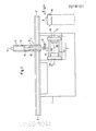
- the injection molding machine 1 shown in the drawing is equipped at one end with a clamping unit 2 for the injection molding tool 3, which has two mold halves 3a and 3b. While the mold half 3a sits on a tool carrier plate 4a of the clamping unit 2, which can be adjusted horizontally along guide rods 4c, the mold half 3b is fastened on a tool carrier plate 4b, which is fixed in position on the guide rods 4c.
- the injection mold 3 can optionally be opened and closed within the clamping unit 2 in the direction of the longitudinal axis 5-5. 1 and 3 of the drawing, the injection mold 3 is shown in the open state, that is to say with the mold halves 3a and 3b moved apart.
- An injection molding removal device 7, which is assigned to the injection molding machine 1, is used to remove the injection molded parts 6 from the injection mold 3.
- the injection molding removal device 7 has a stationary guide bed 8 which extends parallel to the actuating direction of the clamping unit 2, that is to say parallel to its longitudinal axis 5-5, and is also aligned with the longitudinal direction of the injection molding machine 1.
- the guide bed 8 is rigidly connected to the frame or housing of the injection molding machine 1 via a plurality of support arms 9.
- the guide bed 8 carries a longitudinally movable main carriage 10, the one has vertically upward spar 11, on which there is a guide track 12, on which in turn a carriage 13 is slidably arranged.
- the main slide 10 and the slide 13 guided on its spar 11 form a kind of cross support with one another, which has two axes of movement directed at right angles to one another, namely the horizontal Z axis and the vertical Y axis.
- the carriage 13 forms a carrier or cantilever, at the free end of which there is arranged a hanging member 14 which carries at its lower end an injection-molded gripper which, on the one hand, is rotatable about its longitudinal axis and, on the other hand, is pivotable with the hanging member 14 about a transverse axis.
- the arrangement of the injection molding gripper 15 on the hanging member 14 is such that its longitudinal axis coincides with a vertical plane which passes through the longitudinal axis 5-5 of the clamping unit 2, as can be clearly seen in FIG. 2.
- the hanging member 14 and the molded gripper 15 suspended thereon can be lowered in the vertical direction between the guide rods 4c into the clamping unit 2 when it is open, i.e. its tool carrier plates 4a and 4b with the two mold halves 3a and 3b of the injection mold 3 are moved apart, as shown in FIGS. 1 and 3.
- the gripper 15 the individual molded parts can then be removed from the open injection mold 3 in a program-controlled manner and transported away from the working area of the injection molding machine 1.
- the guide bed 8 of the injection molding removal device 7 is extended at least beyond the end face of the injection molding machine 1 or beyond its closing unit 2. However, the guide bed 8 can preferably also be guided beyond the rear of the injection molding machine 1.
- the hanging link 14 is arranged on the slide 13 of the cross support, which is effective as a carrier or cantilever, in its effective length so that it can be optimally adapted to different working conditions, without the movement range of the slide 13 in the direction of this Y axis is affected.
- the arrangement of the injection molding removal device 7 described above relative to the injection molding machine 1 is not only usable where the ' link member 14 is held and guided by a cross support. Rather, it can also be used when the suspension link consists of a linear guide coupling gear 17 designed as a cardan or elliptical link or also as a pantograph, the sliding guide 18 of which is located on a slide 19 which is movable along the guide bed 8.
- the sliding guide 18 for the straight guide coupling gear extends parallel to the guide bed 8 on the slide 19, but essentially transversely to the direction of movement of the free end of the hanging link -14, on which the injection molding gripper 15 is located.
Landscapes
- Engineering & Computer Science (AREA)
- Robotics (AREA)
- Manufacturing & Machinery (AREA)
- Mechanical Engineering (AREA)
- Moulds For Moulding Plastics Or The Like (AREA)
- Injection Moulding Of Plastics Or The Like (AREA)
- Manufacturing Optical Record Carriers (AREA)
Priority Applications (1)
| Application Number | Priority Date | Filing Date | Title |
|---|---|---|---|
| AT86112270T ATE50529T1 (de) | 1985-09-11 | 1986-09-04 | Spritzgiessmaschine mit spritzlingentnahmevorrichtung. |
Applications Claiming Priority (2)
| Application Number | Priority Date | Filing Date | Title |
|---|---|---|---|
| DE19853532299 DE3532299A1 (de) | 1985-09-11 | 1985-09-11 | Spritzgiessmaschine mit spritzling-entnahmevorrichtung |
| DE3532299 | 1985-09-11 |
Publications (2)
| Publication Number | Publication Date |
|---|---|
| EP0218101A1 true EP0218101A1 (fr) | 1987-04-15 |
| EP0218101B1 EP0218101B1 (fr) | 1990-02-28 |
Family
ID=6280585
Family Applications (1)
| Application Number | Title | Priority Date | Filing Date |
|---|---|---|---|
| EP86112270A Expired - Lifetime EP0218101B1 (fr) | 1985-09-11 | 1986-09-04 | Machine à mouler par injection avec un dispositif de déchargement des produits |
Country Status (5)
| Country | Link |
|---|---|
| US (1) | US4781571A (fr) |
| EP (1) | EP0218101B1 (fr) |
| JP (1) | JPS6261769A (fr) |
| AT (1) | ATE50529T1 (fr) |
| DE (2) | DE3532299A1 (fr) |
Cited By (6)
| Publication number | Priority date | Publication date | Assignee | Title |
|---|---|---|---|---|
| DE3830964A1 (de) * | 1988-09-12 | 1990-03-22 | Karl Hehl | Spritzgiessmaschine mit einer einrichtung zur entnahme der spritzteile aus dem spritzwerkzeug |
| EP0438330A1 (fr) * | 1990-01-18 | 1991-07-24 | Henri Vulliez | Dispositif de protection d'articles à usage notamment alimentaire et dispositif de manutention de tels articles pour les conditionner dans des sachets de protection |
| FR2660912A1 (fr) * | 1990-04-11 | 1991-10-18 | Vulliez Henri | Dispositif de manutention d'articles moules a usage notamment alimentaire. |
| EP0589489A3 (en) * | 1988-01-29 | 1994-05-11 | Husky Injection Molding | Sequential injection molding machine |
| DE19614804C2 (de) * | 1996-04-15 | 1999-05-27 | Karl Hehl | Spritzgießmaschine mit einer Entnahmeeinrichtung |
| DE10234041B3 (de) * | 2002-07-26 | 2004-02-19 | Karl Hehl | Entnahmeeinrichtung für eine Kunststoff-Spritzgießmaschine |
Families Citing this family (30)
| Publication number | Priority date | Publication date | Assignee | Title |
|---|---|---|---|---|
| DE3737598C2 (de) * | 1986-11-06 | 1989-11-16 | Mazda Motor | Anlage zur formteilherstellung mit einem formwerkzeug |
| JPS6426420A (en) * | 1987-07-23 | 1989-01-27 | Nissha Printing | Device for injection molding and simultaneous decorating and manufacture of injection-molded and simultaneously decorated product |
| US5017121A (en) * | 1987-12-30 | 1991-05-21 | Karl Hehl | Injection molding machine comprising a protective covering |
| US5052915B1 (en) * | 1988-01-29 | 1998-04-07 | Husky Injection Molding | Sequential injection molding machine |
| US4920762A (en) * | 1988-04-11 | 1990-05-01 | Beckstead Gary K | Cryogenic target and method and apparatus for making same |
| JPH02204016A (ja) * | 1989-02-03 | 1990-08-14 | Toshiba Mach Co Ltd | 射出成形機の製品取出方法および装置 |
| US5000654A (en) * | 1989-12-28 | 1991-03-19 | Star Seiki Co., Ltd. | Reciprocating drive apparatus for automatic molding removing machine |
| DE4017796C1 (fr) * | 1990-06-01 | 1991-12-19 | Richard 8057 Eching De Herbst | |
| DE4110948C3 (de) * | 1991-04-05 | 1997-10-09 | Remak Maschinenbau Gmbh | Verfahren zur Entnahme von Spritzgießartikeln aus einer Spritzgießmaschine |
| AT400235B (de) * | 1991-04-26 | 1995-11-27 | Engel Gmbh Maschbau | Handhabungsvorrichtung zum entfernen geformter kunststoff-spritzlinge |
| US5234328A (en) * | 1991-10-29 | 1993-08-10 | Cbw Automation, Inc. | Retrieval system for removing articles formed by a manufacturing apparatus |
| JP2540790B2 (ja) * | 1992-10-26 | 1996-10-09 | 株式会社山之内製作所 | 氷成形装置 |
| US5388395A (en) * | 1993-04-27 | 1995-02-14 | Air Products And Chemicals, Inc. | Use of nitrogen from an air separation unit as gas turbine air compressor feed refrigerant to improve power output |
| FI97610C (fi) * | 1995-09-26 | 1997-01-27 | Fibox Oy Ab | Laitteisto muovituotteiden valamiseksi |
| DE29802714U1 (de) * | 1998-02-17 | 1998-05-14 | Battenfeld Gmbh, 58540 Meinerzhagen | Vorrichtung zum automatisierten Herstellen von Kunststoff-Formteilen durch Spritzgießen |
| US6332997B1 (en) * | 1998-05-26 | 2001-12-25 | Hardigg Industries Inc. | Method and apparatus for making a one piece battery jar |
| JP2001252954A (ja) * | 2000-03-13 | 2001-09-18 | Star Seiki Co Ltd | 成型品取出し機及び成型品取出し方法 |
| JP4544558B2 (ja) * | 2000-11-22 | 2010-09-15 | 株式会社スター精機 | 成型品取出方法 |
| WO2002076702A1 (fr) * | 2001-02-26 | 2002-10-03 | Jes Tougaard Gram | Systeme d'ejection |
| JP4078893B2 (ja) | 2002-06-19 | 2008-04-23 | 日本精工株式会社 | 車両用衝撃吸収式ステアリングコラム装置 |
| US20040084809A1 (en) * | 2002-11-05 | 2004-05-06 | Vanderploeg James A. | Side shuttle apparatus and method for an injection molding machine |
| US7125244B2 (en) * | 2003-06-06 | 2006-10-24 | Husky Injection Molding Systems Ltd. | In-line robot mount |
| US20060006578A1 (en) * | 2004-07-12 | 2006-01-12 | Polytop Corporation | Vial with hinged cap and method of making same |
| CN101306570B (zh) * | 2007-05-17 | 2011-01-05 | 鸿富锦精密工业(深圳)有限公司 | 模具装置 |
| US7708919B2 (en) * | 2008-05-08 | 2010-05-04 | Delphi Technologies, Inc. | Sprue removal in an injection molding machine |
| BR112012025004A2 (pt) | 2010-04-01 | 2021-05-04 | Athena Automation Ltd. | máquina de moldagem de injeção, combinação de uma máquina de moldagem de injeção e um aparelho robô de entrada lateral para interagir com a máquina, e método de manipular artigos moldados produzidos por uma máquina de moldagem de injeção |
| US8349240B2 (en) | 2011-03-25 | 2013-01-08 | Honda Motor Co., Ltd. | Hidden parting line mold and hidden parting line molding technique using associated part removal device |
| JP4955823B1 (ja) * | 2011-04-05 | 2012-06-20 | 日本省力機械株式会社 | ワーク取り出し仕上げ装置 |
| JP6465615B2 (ja) | 2014-10-22 | 2019-02-06 | 株式会社ユーシン精機 | 成形品取出機 |
| JP7533006B2 (ja) * | 2020-08-19 | 2024-08-14 | セイコーエプソン株式会社 | 射出成形システム |
Citations (4)
| Publication number | Priority date | Publication date | Assignee | Title |
|---|---|---|---|---|
| DE2450218A1 (de) * | 1974-01-09 | 1975-07-10 | Wavin Bv | Verfahren zum selbsttaetigen entformen von spritzgusserzeugnissen und vorrichtung zur durchfuehrung des verfahrens |
| DE2642691A1 (de) * | 1976-09-22 | 1978-03-23 | Uniroyal Ag | Vorrichtung zum entformen einer spritzformeneinheit |
| EP0083766A1 (fr) * | 1982-01-07 | 1983-07-20 | BASF Aktiengesellschaft | Machine à mouler par injection avec un dispositif de déchargement |
| DE3432262A1 (de) * | 1983-11-01 | 1985-05-09 | Netstal-Maschinen AG, Näfels | Handlingeinrichtung an einer kunststoffspritzgiessmaschine |
Family Cites Families (9)
| Publication number | Priority date | Publication date | Assignee | Title |
|---|---|---|---|---|
| US3063108A (en) * | 1959-03-20 | 1962-11-13 | Marx & Co Louis | Automatic die casting machine |
| US3028629A (en) * | 1959-05-18 | 1962-04-10 | Precision Valve Corp | Method and apparatus for forming directional and other indicia on valve operating buttons and caps for pressurized dispensers |
| US3081486A (en) * | 1960-05-09 | 1963-03-19 | Ralph M Hill | Molding apparatus |
| US3669592A (en) * | 1970-04-28 | 1972-06-13 | G W Plastic Eng Inc | Injection molding machines |
| DE2352736C3 (de) * | 1973-10-20 | 1981-05-14 | Owens-Illinois, Inc., 43666 Toledo, Ohio | Überführungseinrichtung für geformte Teile insbesondere aus einer Spritzgießform |
| GB2100658B (en) * | 1978-04-24 | 1983-06-02 | Yoshino Kogyosho Co Ltd | Apparatus for cooling and conveying injection-moulded piece |
| US4243364A (en) * | 1979-11-15 | 1981-01-06 | Husky Injection Molding Systems Inc. | Safety mechanism for injection-molding machine provided with take-off member |
| JPS5894442A (ja) * | 1981-12-01 | 1983-06-04 | Star Seiki:Kk | 射出成型品自動取出装置 |
| US4571320A (en) * | 1984-10-31 | 1986-02-18 | General Motors Corporation | Method and apparatus for loading and unloading sheet molding compound in and from a press |
-
1985
- 1985-09-11 DE DE19853532299 patent/DE3532299A1/de not_active Withdrawn
-
1986
- 1986-09-04 US US06/903,675 patent/US4781571A/en not_active Expired - Lifetime
- 1986-09-04 DE DE8686112270T patent/DE3669125D1/de not_active Revoked
- 1986-09-04 AT AT86112270T patent/ATE50529T1/de not_active IP Right Cessation
- 1986-09-04 EP EP86112270A patent/EP0218101B1/fr not_active Expired - Lifetime
- 1986-09-11 JP JP61214982A patent/JPS6261769A/ja active Granted
Patent Citations (4)
| Publication number | Priority date | Publication date | Assignee | Title |
|---|---|---|---|---|
| DE2450218A1 (de) * | 1974-01-09 | 1975-07-10 | Wavin Bv | Verfahren zum selbsttaetigen entformen von spritzgusserzeugnissen und vorrichtung zur durchfuehrung des verfahrens |
| DE2642691A1 (de) * | 1976-09-22 | 1978-03-23 | Uniroyal Ag | Vorrichtung zum entformen einer spritzformeneinheit |
| EP0083766A1 (fr) * | 1982-01-07 | 1983-07-20 | BASF Aktiengesellschaft | Machine à mouler par injection avec un dispositif de déchargement |
| DE3432262A1 (de) * | 1983-11-01 | 1985-05-09 | Netstal-Maschinen AG, Näfels | Handlingeinrichtung an einer kunststoffspritzgiessmaschine |
Cited By (11)
| Publication number | Priority date | Publication date | Assignee | Title |
|---|---|---|---|---|
| EP0589489A3 (en) * | 1988-01-29 | 1994-05-11 | Husky Injection Molding | Sequential injection molding machine |
| DE3830964A1 (de) * | 1988-09-12 | 1990-03-22 | Karl Hehl | Spritzgiessmaschine mit einer einrichtung zur entnahme der spritzteile aus dem spritzwerkzeug |
| EP0359013A3 (fr) * | 1988-09-12 | 1991-08-07 | Karl Hehl | Presse à mouler des matières plastiques par injection |
| US5039299A (en) * | 1988-09-12 | 1991-08-13 | Karl Hehl | Injection molding machine having an article transfer arrangement |
| EP0438330A1 (fr) * | 1990-01-18 | 1991-07-24 | Henri Vulliez | Dispositif de protection d'articles à usage notamment alimentaire et dispositif de manutention de tels articles pour les conditionner dans des sachets de protection |
| US5161691A (en) * | 1990-01-18 | 1992-11-10 | Henri Vulliez | Protected food utensils |
| US5329746A (en) * | 1990-01-18 | 1994-07-19 | Henri Vulliez | Device for packing protected articles for use in particular with foodstuffs into protective bags |
| FR2660912A1 (fr) * | 1990-04-11 | 1991-10-18 | Vulliez Henri | Dispositif de manutention d'articles moules a usage notamment alimentaire. |
| DE19614804C2 (de) * | 1996-04-15 | 1999-05-27 | Karl Hehl | Spritzgießmaschine mit einer Entnahmeeinrichtung |
| US6386859B1 (en) | 1996-04-15 | 2002-05-14 | Karl Hehl | Injection molding machine with an extractor |
| DE10234041B3 (de) * | 2002-07-26 | 2004-02-19 | Karl Hehl | Entnahmeeinrichtung für eine Kunststoff-Spritzgießmaschine |
Also Published As
| Publication number | Publication date |
|---|---|
| DE3532299A1 (de) | 1987-03-19 |
| DE3669125D1 (de) | 1990-04-05 |
| EP0218101B1 (fr) | 1990-02-28 |
| JPH0240418B2 (fr) | 1990-09-11 |
| JPS6261769A (ja) | 1987-03-18 |
| US4781571A (en) | 1988-11-01 |
| ATE50529T1 (de) | 1990-03-15 |
Similar Documents
| Publication | Publication Date | Title |
|---|---|---|
| EP0218101B1 (fr) | Machine à mouler par injection avec un dispositif de déchargement des produits | |
| DE3346523C2 (de) | Vorrichtung zum Zusammenbau eines Kraftfahrzeug-Körpers | |
| EP0595074A1 (fr) | Dispositif de serrage | |
| DE102009048863A1 (de) | Werkstück-Umsetz-Robotersystem | |
| DE3202353A1 (de) | Pantographengestaenge | |
| DE102006038505A1 (de) | Vorrichtung zum Versetzen von Gegenständen | |
| DE2546472B2 (de) | Vorrichtung zum seitlichen Verschieben der Halterung des Auslegers eines Baggers o.dgl | |
| DE2315950C2 (de) | Werkstücktransportvorrichtung, insbesondere für Blechteile an Pressen | |
| DE19841243B4 (de) | Industrieroboter | |
| EP0181490B1 (fr) | Dispositif pour engendrer des mouvements cartésiens horizontaux et verticaux | |
| EP0307645B1 (fr) | Dispositif manipulateur destiné à un système de montage et comportant un élément porteur et un élément coulissant | |
| EP0360168A2 (fr) | Machine-outil | |
| DE3505836A1 (de) | Spritzgiessmaschine mit spritzling-entnahmevorrichtung | |
| CH673831A5 (fr) | ||
| EP0273932B1 (fr) | Dispositif de changement d'outils pour machines-outils | |
| DE10012665C2 (de) | Werkzeugwechselvorrichtung für eine Werkzeugmaschine | |
| EP0255567B1 (fr) | Changeur d'outils pour machine universelle à percer et à fraiser | |
| EP0142749B1 (fr) | Dispositif de changement d'outil pour machine-outil multibroche | |
| EP0157950A2 (fr) | Machine-outil avec une poupée mobile suivant plusieurs axes | |
| DE212080T1 (de) | Vorrichtung zum ausziehen eines elementes aus einem zusammenbau. | |
| DE3017164C2 (de) | Lastaufnahme-Vorrichtung für Regalstapelfahrzeuge | |
| DE3541563A1 (de) | Werkzeugwechsler | |
| DE3034700C2 (de) | Elektrische Widerstandsschweißzange | |
| EP0284808B1 (fr) | Machine d'usinage par étincelles | |
| DE4009537C2 (fr) |
Legal Events
| Date | Code | Title | Description |
|---|---|---|---|
| PUAI | Public reference made under article 153(3) epc to a published international application that has entered the european phase |
Free format text: ORIGINAL CODE: 0009012 |
|
| 17P | Request for examination filed |
Effective date: 19860922 |
|
| AK | Designated contracting states |
Kind code of ref document: A1 Designated state(s): AT BE CH DE FR GB IT LI LU NL SE |
|
| 17Q | First examination report despatched |
Effective date: 19871204 |
|
| GRAA | (expected) grant |
Free format text: ORIGINAL CODE: 0009210 |
|
| AK | Designated contracting states |
Kind code of ref document: B1 Designated state(s): AT BE CH DE FR GB IT LI LU NL SE |
|
| PG25 | Lapsed in a contracting state [announced via postgrant information from national office to epo] |
Ref country code: IT Free format text: LAPSE BECAUSE OF FAILURE TO SUBMIT A TRANSLATION OF THE DESCRIPTION OR TO PAY THE FEE WITHIN THE PRE;WARNING: LAPSES OF ITALIAN PATENTS WITH EFFECTIVE DATE BEFORE 2007 MAY HAVE OCCURRED AT ANY TIME BEFORE 2007. THE CORRECT EFFECTIVE DATE MAY BE DIFFERENT FROM THE ONE RECORDED.SCRIBED TIME-LIMIT Effective date: 19900228 Ref country code: NL Effective date: 19900228 Ref country code: SE Effective date: 19900228 |
|
| REF | Corresponds to: |
Ref document number: 50529 Country of ref document: AT Date of ref document: 19900315 Kind code of ref document: T |
|
| REF | Corresponds to: |
Ref document number: 3669125 Country of ref document: DE Date of ref document: 19900405 |
|
| GBT | Gb: translation of ep patent filed (gb section 77(6)(a)/1977) | ||
| ET | Fr: translation filed | ||
| PGFP | Annual fee paid to national office [announced via postgrant information from national office to epo] |
Ref country code: AT Payment date: 19900730 Year of fee payment: 5 |
|
| PGFP | Annual fee paid to national office [announced via postgrant information from national office to epo] |
Ref country code: FR Payment date: 19900801 Year of fee payment: 5 Ref country code: LU Payment date: 19900801 Year of fee payment: 5 |
|
| NLV1 | Nl: lapsed or annulled due to failure to fulfill the requirements of art. 29p and 29m of the patents act | ||
| PGFP | Annual fee paid to national office [announced via postgrant information from national office to epo] |
Ref country code: GB Payment date: 19900904 Year of fee payment: 5 |
|
| PG25 | Lapsed in a contracting state [announced via postgrant information from national office to epo] |
Ref country code: LU Free format text: LAPSE BECAUSE OF NON-PAYMENT OF DUE FEES Effective date: 19900930 Ref country code: LI Free format text: LAPSE BECAUSE OF NON-PAYMENT OF DUE FEES Effective date: 19900930 Ref country code: CH Free format text: LAPSE BECAUSE OF NON-PAYMENT OF DUE FEES Effective date: 19900930 |
|
| PGFP | Annual fee paid to national office [announced via postgrant information from national office to epo] |
Ref country code: BE Payment date: 19901005 Year of fee payment: 5 |
|
| PGFP | Annual fee paid to national office [announced via postgrant information from national office to epo] |
Ref country code: DE Payment date: 19901102 Year of fee payment: 5 |
|
| PLBI | Opposition filed |
Free format text: ORIGINAL CODE: 0009260 |
|
| PLBI | Opposition filed |
Free format text: ORIGINAL CODE: 0009260 |
|
| 26 | Opposition filed |
Opponent name: ARBURG MASCHINENFABRIK HEHL & SOEHNE GMBH & CO. KG Effective date: 19901122 |
|
| 26 | Opposition filed |
Opponent name: ARBURG MASCHINENFABRIK HEHL & SOEHNE GMBH & CO. KG Effective date: 19901122 Opponent name: REMAK - MASCHINENBAU GMBH Effective date: 19901127 |
|
| REG | Reference to a national code |
Ref country code: CH Ref legal event code: PL |
|
| RDAG | Patent revoked |
Free format text: ORIGINAL CODE: 0009271 |
|
| STAA | Information on the status of an ep patent application or granted ep patent |
Free format text: STATUS: PATENT REVOKED |
|
| 27W | Patent revoked |
Effective date: 19910528 |
|
| GBPR | Gb: patent revoked under art. 102 of the ep convention designating the uk as contracting state | ||
| BERE | Be: lapsed |
Owner name: BATTENFELD KUNSTSTOFFMASCHINEN G.M.B.H. Effective date: 19910930 |