EP0218219A2 - Vorrichtung zur Messung des optischen Vermögens - Google Patents
Vorrichtung zur Messung des optischen Vermögens Download PDFInfo
- Publication number
- EP0218219A2 EP0218219A2 EP86113739A EP86113739A EP0218219A2 EP 0218219 A2 EP0218219 A2 EP 0218219A2 EP 86113739 A EP86113739 A EP 86113739A EP 86113739 A EP86113739 A EP 86113739A EP 0218219 A2 EP0218219 A2 EP 0218219A2
- Authority
- EP
- European Patent Office
- Prior art keywords
- photo
- signal
- incident light
- light path
- detection
- Prior art date
- Legal status (The legal status is an assumption and is not a legal conclusion. Google has not performed a legal analysis and makes no representation as to the accuracy of the status listed.)
- Granted
Links
Images

Classifications
-
- G—PHYSICS
- G01—MEASURING; TESTING
- G01J—MEASUREMENT OF INTENSITY, VELOCITY, SPECTRAL CONTENT, POLARISATION, PHASE OR PULSE CHARACTERISTICS OF INFRARED, VISIBLE OR ULTRAVIOLET LIGHT; COLORIMETRY; RADIATION PYROMETRY
- G01J1/00—Photometry, e.g. photographic exposure meter
- G01J1/42—Photometry, e.g. photographic exposure meter using electric radiation detectors
-
- G—PHYSICS
- G01—MEASURING; TESTING
- G01J—MEASUREMENT OF INTENSITY, VELOCITY, SPECTRAL CONTENT, POLARISATION, PHASE OR PULSE CHARACTERISTICS OF INFRARED, VISIBLE OR ULTRAVIOLET LIGHT; COLORIMETRY; RADIATION PYROMETRY
- G01J1/00—Photometry, e.g. photographic exposure meter
- G01J1/02—Details
- G01J1/04—Optical or mechanical part supplementary adjustable parts
- G01J1/0488—Optical or mechanical part supplementary adjustable parts with spectral filtering
Definitions
- the present invention relates to an optical power meter and more paticularly, to an optical power meter for selectively switching at least two photo-detectors.
- an optical power meter is used to measure the optical characteristics of a light emission element and the transmission characteristics of the optical signal in an optical fiber.
- a photoelectric conversion element such as a photodiode and a photo-transistor is provided as a photo detector of the optical power meter.
- the photoelectric conversion element has the characteristics of wavelength sensitivity according to which the photoelectric conversion element responds to the wavelength given thereto. Since the characteristics of wavelength sensitivity of the photoelectric conversion element are fixed, the light of which the wavelength is outside the region of the characteristics of wavelength sensitivity cannot be detected. The characteristics of wavelength sensitivity can cover only a narrow region of the wavelength.
- a plurality of photoelectric conversion elements must be provided of which the respective wavelength sensitivity characteristics can cover only some parts of the wide wavelength range. Depending on these parts of the wavelength region therefore an appropriate one of the plurality of photoelectric conversion elements must be selected and exchanged. Thus, the measurement of the optical power is troublesome.
- an optical power meter system comprises chopper means with a total reflection mirror, at least two photo-detectors of the different characteristics of wavelength sensitivity, and comparator means for comparing the photo-detectors signals derived from the two photo-detectors and outputting an optical detection signal of a higher level.
- the chopper is positioned in an incident light path.
- the photo-detection are positioned in a first path of the light passing beside the chopper and in a second path of the light reflected by the chopper, respectively.
- the comparator in the first preferred embodiment can be replaced by adder means for adding the photo-detection signals derived from the two photo-detectors.
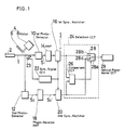
- FIG.1 is a block diagram of an optical power meter according to one preferred embodiment of the present invention.
- the optical power meter system 1 receives the optical signal under the measurement through an optical fiber 2.
- a light chopper 4 is disposed in an incident light path 1.
- the light chopper 4 includes a semicircular total reflection mirror 6 which is positioned in the incident light path 1 with being tilted at a predetermined angle, preferably, 45° ,smaller than 90° .
- the total reflection mirror 6 is coupled to the axis of rotation of a motor 8.
- a first photo-detector 10 is positioned in the path of the light unreflected by the total reflection mirror 6 of the chopper 4.
- a second photo-detector 12 is positioned in the path of the light reflected by the total reflection mirror 6 of the chopper 4.
- the first photo-detector 10 comprises a first photoelectric conversion element providing a peak value at a wavelength ⁇ 1 ( lambda 1 ) while the second photo-detector 12 comprises a second photoelectric conversion element providing a peak value at a wavelength ⁇ 2 ( lambda 2 ).
- An amplifier 14 is provided for amplifying a photo-detection signal delivered from the first photo-detector 10.
- a first synchronous rectifier 16 is provided for synchronously rectifying the photo-detection signal outputted by the amplifier 14.
- a phase-reverse amplifier 18 is provided for amplifying a photo-detection signal delivered from the second photo detector 12 and reversing the phase of the photo-detection signal at 180° .
- a second synchronous rectifier 20 is connected to synchronously rectify the photo-detection signal outputted by the phase-reverse amplifier 18.
- a synchronous-signal generator 23 with a light source and a photo-detector is coupled to the optical chopper 4 and an output signal of the generator 23 is applied to the first synchronous rectifier 16 and the second synchronous rectifier 20 through the synchronous signal circuit 22.
- a selection circuit 24 is provided for selectively outputting the photo-detection signal of a higher level by comparing the photo-detection signals delivered from the first and the second photo-detectors 10 and 12.
- the selection circuit 24 comprises a comparison circuit 26 and a switch 28.
- the comparison circuit 26 is responsive to the photo-detection signals from the first and the second photo-detectors 10 and 12 to compare the levels of the photo-detection signals in order to output a comparison signal representing which photo detection signal is great.
- the switch 28 is responsive to the comparison signal outputted by the comparison circuit 26 to switch the photo-detection signals outputted by the first and the second synchronous rectifiers 16 and 20.
- the switch 28 has three terminals 28a, 28b, and 28c.
- An optical power meter circuit 29 is coupled to the terminal 28a.
- the light signal from the optical fiber 2 is incident on the chopper 4 to measure the power of the optical signals with the above-arranged optical power meter.
- the light from the optical fiber 2 is split to the detectors 10 and 12 by the optical chopper 4, alternatively. Therefore, each output of the detector 10 or 12 has an alternative signal which has 180° phase difference each other, as shown in FIG. 3.
- the output signal S1 of the detector 10 is amplified by the amplifier 14, so that the amplified signal is rectified by the first synchronous rectifier 16 with the synchronous signal outputted by the synchronous-signal circuit 22.
- the synchronously rectified output is applied to the terminal 28b of the switch 28 and to a first input terminal of the comparison circuit 26.
- the output signal S2 of the second detector 12 is amplified and phase-reversed at 180° by the phase-reverse amplifier 18 in order to produce a signal S2' in phase of signal S1.
- This rectifier signal S2' is applied to the second synchronous rectifier 20, so that it is synchronously rectified with the synchronous signal outputted by the synchronous signal circuit 22.
- the synchronously rectified output is applied to the terminal 28c of the switch 28 and to a second input terminal of the comparison circuit 26.
- the comparison circuit 26 compares the output signal levels of the first and second synchronous rectifiers 16 and 20. It outputs the comparison signal representing which of the signals S1 and S2 has a larger level.
- the comparison signal is applied to the switch 28.
- the switch 28 is responsive to the comparison signal to connect the common terminal 28a to the terminal 28b.
- the switch 28 is responsive to the comparison signal to connect the common terminal 28a to the terminal 28c.
- the switch 28 is switched so as to receive the photo-dectection signal of a higher level in response to the comparison of the levels of the photo-detection signals S1 and S2.
- the selection circuit 24, therefore, can continue to output the photo-detection signal derived from the photo-detector 10 or 12 which can appropriately respond to the wavelength of the optical signal under measurement.
- the power of the optical signal over the added wavelength zones of the first and second photo-detectors 10 and 12 can be measured by the above-arranged optical power meter system 1.
- the total reflection mirror 6 is rotated by the motor 8, but it should not be limited to this. It may be possible that the total reflection mirror 6 is merely slided into the incident light path I with remaining tilted.
- a tuning amplifier and a rectifier circuit may be combined in which case the phase-reverse amplifier 18 and the synchronous signal circuit 22 can be omitted.
- an adder 30 as shown in FIG. 4 can be provided for adding the synchronously detected output signals from the first and the second synchronous rectifiers 16 and 20.
- the output of the adder 30 is shown in the chain line and the solid line of FIG. 5, so that the additive characteristics of the photo-sensitivity of the first and the second synchronous rectifiers 16 and 20 can be obtained.
- the light signal from the optical fiber 2 is chopped by the chopper 4 to alternatively switch the light path for the straightly incident light and the reflected light.
- the straightly incident light and the reflected light are introduced into the photo-detectors respectively having the different characteristics of the wavelength sensitivity.
- Each of the photo-detectors outputs the photo-detection signal which is inputted into the comparison circuit.
- the comparison circuit compares the photo-detection signals so as to produce the comparison signal indicating either of the photo-detection signals of a higher level.
- the comparison circuit outputs the comparison signal indicating which of the photo-detectors has sensitivity suitable for the wavelength of the light under the measurement.
- the adder may be provided for adding the photo-detection signal levels obtained by the photo-detectors.
- the power of the optical signal can be efficiently and effectively measured over the wide rangeof the wavelength without having to change photo-electric conversion elements.
Landscapes
- Physics & Mathematics (AREA)
- General Physics & Mathematics (AREA)
- Spectroscopy & Molecular Physics (AREA)
- Photometry And Measurement Of Optical Pulse Characteristics (AREA)
- Spectrometry And Color Measurement (AREA)
Applications Claiming Priority (2)
| Application Number | Priority Date | Filing Date | Title |
|---|---|---|---|
| JP224576/85 | 1985-10-08 | ||
| JP60224576A JPS6283625A (ja) | 1985-10-08 | 1985-10-08 | 光パワ−メ−タ |
Publications (3)
| Publication Number | Publication Date |
|---|---|
| EP0218219A2 true EP0218219A2 (de) | 1987-04-15 |
| EP0218219A3 EP0218219A3 (en) | 1989-05-17 |
| EP0218219B1 EP0218219B1 (de) | 1992-01-15 |
Family
ID=16815905
Family Applications (1)
| Application Number | Title | Priority Date | Filing Date |
|---|---|---|---|
| EP86113739A Expired EP0218219B1 (de) | 1985-10-08 | 1986-10-03 | Vorrichtung zur Messung des optischen Vermögens |
Country Status (4)
| Country | Link |
|---|---|
| US (1) | US4749275A (de) |
| EP (1) | EP0218219B1 (de) |
| JP (1) | JPS6283625A (de) |
| DE (1) | DE3683437D1 (de) |
Cited By (1)
| Publication number | Priority date | Publication date | Assignee | Title |
|---|---|---|---|---|
| US5634938A (en) * | 1992-01-30 | 1997-06-03 | Cardiac Pacemakers, Inc. | Defibrillator waveform generator for generating waveform of long duration |
Families Citing this family (8)
| Publication number | Priority date | Publication date | Assignee | Title |
|---|---|---|---|---|
| GB8605394D0 (en) * | 1986-03-05 | 1986-05-08 | Nat Radiological Protection Bo | Radiation detector |
| JPH03210438A (ja) * | 1990-01-16 | 1991-09-13 | Anritsu Corp | 光波長測定装置 |
| US5087808A (en) * | 1991-02-26 | 1992-02-11 | Reed Edwin A | Combined optical power and noise meter |
| US5262639A (en) * | 1992-04-15 | 1993-11-16 | Norscan Instruments Ltd. | Fiber optic cable monitoring method and apparatus including moisture detection and bending loss detection |
| US5805277A (en) * | 1997-08-06 | 1998-09-08 | Coherent, Inc. | Portable laser power measuring apparatus |
| US6208370B1 (en) | 1998-12-22 | 2001-03-27 | Eastman Kodak Company | Method and apparatus for determining the starting position and the power of a scanning light beam to be used in writing on a media |
| JP2002071511A (ja) * | 2000-08-31 | 2002-03-08 | Ando Electric Co Ltd | 光学部品測定装置及び光学部品の試験方法 |
| JP2003322563A (ja) * | 2002-04-30 | 2003-11-14 | Ando Electric Co Ltd | 光パワーメータ |
Family Cites Families (6)
| Publication number | Priority date | Publication date | Assignee | Title |
|---|---|---|---|---|
| DE1472283B2 (de) * | 1966-06-02 | 1971-02-18 | Ernst Leitz Gmbh, 6330 Wetzlar | Zweistrahlfotometer |
| FR1598834A (de) * | 1968-12-27 | 1970-07-06 | ||
| US3981591A (en) * | 1972-09-04 | 1976-09-21 | Nippon Kogaku K.K. | Automatic photometer |
| US4223215A (en) * | 1978-05-19 | 1980-09-16 | The Perkin-Elmer Corporation | Photodetector arrangements and circuits |
| US4260255A (en) * | 1979-10-22 | 1981-04-07 | The United States Of America As Represented By The Secretary Of The Army | High energy laser beam sampling meter |
| US4467203A (en) * | 1981-10-19 | 1984-08-21 | Panametrics, Inc. | Low noise amplifier and method for energy biased radiation sensitive receiver |
-
1985
- 1985-10-08 JP JP60224576A patent/JPS6283625A/ja active Granted
-
1986
- 1986-09-30 US US06/913,252 patent/US4749275A/en not_active Expired - Fee Related
- 1986-10-03 EP EP86113739A patent/EP0218219B1/de not_active Expired
- 1986-10-03 DE DE8686113739T patent/DE3683437D1/de not_active Expired - Fee Related
Cited By (1)
| Publication number | Priority date | Publication date | Assignee | Title |
|---|---|---|---|---|
| US5634938A (en) * | 1992-01-30 | 1997-06-03 | Cardiac Pacemakers, Inc. | Defibrillator waveform generator for generating waveform of long duration |
Also Published As
| Publication number | Publication date |
|---|---|
| DE3683437D1 (de) | 1992-02-27 |
| EP0218219A3 (en) | 1989-05-17 |
| US4749275A (en) | 1988-06-07 |
| JPH0378921B2 (de) | 1991-12-17 |
| EP0218219B1 (de) | 1992-01-15 |
| JPS6283625A (ja) | 1987-04-17 |
Similar Documents
| Publication | Publication Date | Title |
|---|---|---|
| CA1108430A (en) | Optical measurement system | |
| EP0218219B1 (de) | Vorrichtung zur Messung des optischen Vermögens | |
| US4758086A (en) | Apparatus for measuring spectral power of a light beam | |
| CA1044055A (en) | Signal processor for focus detecting apparatus | |
| JPH08265263A (ja) | 双方向光空間伝送装置 | |
| US4305664A (en) | Spectrophotometer | |
| CN211978136U (zh) | 一种激光波长与功率监测装置 | |
| KR100387288B1 (ko) | 파장분할 다중방식 광통신에서 광신호의 파장과 광 세기와광신호 대 잡음비를 측정하는 장치 | |
| JPH01250778A (ja) | 光学検出装置 | |
| EP0600636A1 (de) | Selbstkalibrierter Leistungsmesser | |
| JP3223789B2 (ja) | レーザ測長器 | |
| SU1578504A1 (ru) | Фотоприемное устройство | |
| JPS6217621A (ja) | 光パワ−メ−タ | |
| JPS6285832A (ja) | 光学式温度計 | |
| SU1663420A1 (ru) | Оптико-электронное устройство дл измерени линейных смещений | |
| SU1078289A1 (ru) | Цифровой регистратор углового смещени света в атмосфере | |
| SU1442839A1 (ru) | Двухканальный фотометр | |
| SU1362947A1 (ru) | Логарифмирующий фотометр | |
| SU1316388A1 (ru) | Устройство дл измерени коэффициентов отражени | |
| SU1481602A1 (ru) | Прозрачномер | |
| JPS6144334A (ja) | 温度測定装置 | |
| SU1402807A2 (ru) | Устройство дл измерени малых зазоров | |
| SU1137403A1 (ru) | Устройство дл бесконтактного измерени силы тока | |
| SU737990A1 (ru) | Оптоэлектронное запоминающее устройство | |
| SU1695127A1 (ru) | Блок нормировани дл измерител с генератором накачки лазера и четырехплощадочным квадрантным фотоприемником |
Legal Events
| Date | Code | Title | Description |
|---|---|---|---|
| PUAI | Public reference made under article 153(3) epc to a published international application that has entered the european phase |
Free format text: ORIGINAL CODE: 0009012 |
|
| AK | Designated contracting states |
Kind code of ref document: A2 Designated state(s): DE FR GB |
|
| PUAL | Search report despatched |
Free format text: ORIGINAL CODE: 0009013 |
|
| AK | Designated contracting states |
Kind code of ref document: A3 Designated state(s): DE FR GB |
|
| 17P | Request for examination filed |
Effective date: 19890427 |
|
| 17Q | First examination report despatched |
Effective date: 19910312 |
|
| GRAA | (expected) grant |
Free format text: ORIGINAL CODE: 0009210 |
|
| AK | Designated contracting states |
Kind code of ref document: B1 Designated state(s): DE FR GB |
|
| REF | Corresponds to: |
Ref document number: 3683437 Country of ref document: DE Date of ref document: 19920227 |
|
| ET | Fr: translation filed | ||
| PGFP | Annual fee paid to national office [announced via postgrant information from national office to epo] |
Ref country code: GB Payment date: 19921002 Year of fee payment: 7 |
|
| PGFP | Annual fee paid to national office [announced via postgrant information from national office to epo] |
Ref country code: FR Payment date: 19921019 Year of fee payment: 7 |
|
| PGFP | Annual fee paid to national office [announced via postgrant information from national office to epo] |
Ref country code: DE Payment date: 19921029 Year of fee payment: 7 |
|
| PLBE | No opposition filed within time limit |
Free format text: ORIGINAL CODE: 0009261 |
|
| STAA | Information on the status of an ep patent application or granted ep patent |
Free format text: STATUS: NO OPPOSITION FILED WITHIN TIME LIMIT |
|
| 26N | No opposition filed | ||
| PG25 | Lapsed in a contracting state [announced via postgrant information from national office to epo] |
Ref country code: GB Effective date: 19931003 |
|
| GBPC | Gb: european patent ceased through non-payment of renewal fee |
Effective date: 19931003 |
|
| PG25 | Lapsed in a contracting state [announced via postgrant information from national office to epo] |
Ref country code: FR Effective date: 19940630 |
|
| PG25 | Lapsed in a contracting state [announced via postgrant information from national office to epo] |
Ref country code: DE Effective date: 19940701 |
|
| REG | Reference to a national code |
Ref country code: FR Ref legal event code: ST |