EP0218660B2 - Verfahren und vorrichtung zur erzeugung von ozon - Google Patents
Verfahren und vorrichtung zur erzeugung von ozon Download PDFInfo
- Publication number
- EP0218660B2 EP0218660B2 EP86902421A EP86902421A EP0218660B2 EP 0218660 B2 EP0218660 B2 EP 0218660B2 EP 86902421 A EP86902421 A EP 86902421A EP 86902421 A EP86902421 A EP 86902421A EP 0218660 B2 EP0218660 B2 EP 0218660B2
- Authority
- EP
- European Patent Office
- Prior art keywords
- ozone
- oxygen
- gas
- adsorption
- loop
- Prior art date
- Legal status (The legal status is an assumption and is not a legal conclusion. Google has not performed a legal analysis and makes no representation as to the accuracy of the status listed.)
- Expired - Lifetime
Links
- CBENFWSGALASAD-UHFFFAOYSA-N Ozone Chemical compound [O-][O+]=O CBENFWSGALASAD-UHFFFAOYSA-N 0.000 title claims description 70
- 238000004519 manufacturing process Methods 0.000 title claims description 27
- 238000000034 method Methods 0.000 title claims description 24
- 239000007789 gas Substances 0.000 claims abstract description 68
- 239000000203 mixture Substances 0.000 claims abstract description 61
- 239000001301 oxygen Substances 0.000 claims abstract description 52
- 229910052760 oxygen Inorganic materials 0.000 claims abstract description 52
- QVGXLLKOCUKJST-UHFFFAOYSA-N atomic oxygen Chemical compound [O] QVGXLLKOCUKJST-UHFFFAOYSA-N 0.000 claims abstract description 51
- 238000001179 sorption measurement Methods 0.000 claims abstract description 47
- 238000003795 desorption Methods 0.000 claims abstract description 43
- OGIIWTRTOXDWEH-UHFFFAOYSA-N [O].[O-][O+]=O Chemical compound [O].[O-][O+]=O OGIIWTRTOXDWEH-UHFFFAOYSA-N 0.000 claims abstract description 33
- 238000006467 substitution reaction Methods 0.000 claims abstract description 33
- 238000006385 ozonation reaction Methods 0.000 claims abstract description 13
- 238000001816 cooling Methods 0.000 claims abstract description 4
- 238000004821 distillation Methods 0.000 claims abstract description 4
- 230000002000 scavenging effect Effects 0.000 claims abstract 13
- 238000005192 partition Methods 0.000 claims description 47
- 239000003463 adsorbent Substances 0.000 claims description 31
- 230000008569 process Effects 0.000 claims description 17
- 238000011144 upstream manufacturing Methods 0.000 claims description 8
- 239000000463 material Substances 0.000 claims description 3
- 238000004891 communication Methods 0.000 claims description 2
- 230000006835 compression Effects 0.000 claims description 2
- 238000007906 compression Methods 0.000 claims description 2
- 239000013589 supplement Substances 0.000 claims description 2
- 230000000063 preceeding effect Effects 0.000 claims 1
- IJGRMHOSHXDMSA-UHFFFAOYSA-N Atomic nitrogen Chemical compound N#N IJGRMHOSHXDMSA-UHFFFAOYSA-N 0.000 abstract description 103
- 229910052757 nitrogen Inorganic materials 0.000 abstract description 51
- VYPSYNLAJGMNEJ-UHFFFAOYSA-N Silicium dioxide Chemical compound O=[Si]=O VYPSYNLAJGMNEJ-UHFFFAOYSA-N 0.000 abstract description 3
- 239000000741 silica gel Substances 0.000 abstract description 3
- 229910002027 silica gel Inorganic materials 0.000 abstract description 3
- 239000012071 phase Substances 0.000 description 31
- 238000009434 installation Methods 0.000 description 29
- PNBAHWFGUWWTQC-UHFFFAOYSA-N [N].[O-][O+]=O Chemical compound [N].[O-][O+]=O PNBAHWFGUWWTQC-UHFFFAOYSA-N 0.000 description 10
- 238000010586 diagram Methods 0.000 description 8
- 238000010408 sweeping Methods 0.000 description 8
- 238000000926 separation method Methods 0.000 description 6
- 239000012159 carrier gas Substances 0.000 description 5
- 238000007789 sealing Methods 0.000 description 5
- 230000001154 acute effect Effects 0.000 description 4
- 238000011084 recovery Methods 0.000 description 4
- MYMOFIZGZYHOMD-UHFFFAOYSA-N Dioxygen Chemical compound O=O MYMOFIZGZYHOMD-UHFFFAOYSA-N 0.000 description 3
- 230000008901 benefit Effects 0.000 description 3
- 239000000243 solution Substances 0.000 description 3
- 230000000153 supplemental effect Effects 0.000 description 3
- OLBVUFHMDRJKTK-UHFFFAOYSA-N [N].[O] Chemical compound [N].[O] OLBVUFHMDRJKTK-UHFFFAOYSA-N 0.000 description 2
- 238000009826 distribution Methods 0.000 description 2
- 235000021183 entrée Nutrition 0.000 description 2
- 239000012530 fluid Substances 0.000 description 2
- 239000007788 liquid Substances 0.000 description 2
- 150000002829 nitrogen Chemical class 0.000 description 2
- 238000010926 purge Methods 0.000 description 2
- 230000009467 reduction Effects 0.000 description 2
- PEDCQBHIVMGVHV-UHFFFAOYSA-N Glycerine Chemical compound OCC(O)CO PEDCQBHIVMGVHV-UHFFFAOYSA-N 0.000 description 1
- 239000002250 absorbent Substances 0.000 description 1
- 230000002745 absorbent Effects 0.000 description 1
- 230000006978 adaptation Effects 0.000 description 1
- 230000033228 biological regulation Effects 0.000 description 1
- 230000008859 change Effects 0.000 description 1
- 230000008878 coupling Effects 0.000 description 1
- 238000010168 coupling process Methods 0.000 description 1
- 238000005859 coupling reaction Methods 0.000 description 1
- 125000004122 cyclic group Chemical group 0.000 description 1
- 230000007423 decrease Effects 0.000 description 1
- 230000000694 effects Effects 0.000 description 1
- 229940082150 encore Drugs 0.000 description 1
- 238000002347 injection Methods 0.000 description 1
- 239000007924 injection Substances 0.000 description 1
- 239000007791 liquid phase Substances 0.000 description 1
- 238000012423 maintenance Methods 0.000 description 1
- 239000002184 metal Substances 0.000 description 1
- 238000002156 mixing Methods 0.000 description 1
- 239000012299 nitrogen atmosphere Substances 0.000 description 1
- 150000002926 oxygen Chemical class 0.000 description 1
- 230000002093 peripheral effect Effects 0.000 description 1
- 239000000047 product Substances 0.000 description 1
- 238000000746 purification Methods 0.000 description 1
- 238000005057 refrigeration Methods 0.000 description 1
- 230000008929 regeneration Effects 0.000 description 1
- 238000011069 regeneration method Methods 0.000 description 1
- 230000000630 rising effect Effects 0.000 description 1
- 239000007787 solid Substances 0.000 description 1
- 239000006200 vaporizer Substances 0.000 description 1
Images





Classifications
-
- C—CHEMISTRY; METALLURGY
- C01—INORGANIC CHEMISTRY
- C01B—NON-METALLIC ELEMENTS; COMPOUNDS THEREOF; METALLOIDS OR COMPOUNDS THEREOF NOT COVERED BY SUBCLASS C01C
- C01B13/00—Oxygen; Ozone; Oxides or hydroxides in general
- C01B13/10—Preparation of ozone
-
- B—PERFORMING OPERATIONS; TRANSPORTING
- B01—PHYSICAL OR CHEMICAL PROCESSES OR APPARATUS IN GENERAL
- B01J—CHEMICAL OR PHYSICAL PROCESSES, e.g. CATALYSIS OR COLLOID CHEMISTRY; THEIR RELEVANT APPARATUS
- B01J8/00—Chemical or physical processes in general, conducted in the presence of fluids and solid particles; Apparatus for such processes
- B01J8/02—Chemical or physical processes in general, conducted in the presence of fluids and solid particles; Apparatus for such processes with stationary particles, e.g. in fixed beds
- B01J8/0207—Chemical or physical processes in general, conducted in the presence of fluids and solid particles; Apparatus for such processes with stationary particles, e.g. in fixed beds the fluid flow within the bed being predominantly horizontal
- B01J8/0214—Chemical or physical processes in general, conducted in the presence of fluids and solid particles; Apparatus for such processes with stationary particles, e.g. in fixed beds the fluid flow within the bed being predominantly horizontal in a cylindrical annular shaped bed
-
- B—PERFORMING OPERATIONS; TRANSPORTING
- B01—PHYSICAL OR CHEMICAL PROCESSES OR APPARATUS IN GENERAL
- B01J—CHEMICAL OR PHYSICAL PROCESSES, e.g. CATALYSIS OR COLLOID CHEMISTRY; THEIR RELEVANT APPARATUS
- B01J8/00—Chemical or physical processes in general, conducted in the presence of fluids and solid particles; Apparatus for such processes
- B01J8/02—Chemical or physical processes in general, conducted in the presence of fluids and solid particles; Apparatus for such processes with stationary particles, e.g. in fixed beds
- B01J8/0242—Chemical or physical processes in general, conducted in the presence of fluids and solid particles; Apparatus for such processes with stationary particles, e.g. in fixed beds the fluid flow within the bed being predominantly vertical
- B01J8/0257—Chemical or physical processes in general, conducted in the presence of fluids and solid particles; Apparatus for such processes with stationary particles, e.g. in fixed beds the fluid flow within the bed being predominantly vertical in a cylindrical annular shaped bed
-
- B—PERFORMING OPERATIONS; TRANSPORTING
- B01—PHYSICAL OR CHEMICAL PROCESSES OR APPARATUS IN GENERAL
- B01J—CHEMICAL OR PHYSICAL PROCESSES, e.g. CATALYSIS OR COLLOID CHEMISTRY; THEIR RELEVANT APPARATUS
- B01J8/00—Chemical or physical processes in general, conducted in the presence of fluids and solid particles; Apparatus for such processes
- B01J8/08—Chemical or physical processes in general, conducted in the presence of fluids and solid particles; Apparatus for such processes with moving particles
- B01J8/10—Chemical or physical processes in general, conducted in the presence of fluids and solid particles; Apparatus for such processes with moving particles moved by stirrers or by rotary drums or rotary receptacles or endless belts
-
- B—PERFORMING OPERATIONS; TRANSPORTING
- B01—PHYSICAL OR CHEMICAL PROCESSES OR APPARATUS IN GENERAL
- B01D—SEPARATION
- B01D2256/00—Main component in the product gas stream after treatment
- B01D2256/14—Ozone
-
- B—PERFORMING OPERATIONS; TRANSPORTING
- B01—PHYSICAL OR CHEMICAL PROCESSES OR APPARATUS IN GENERAL
- B01J—CHEMICAL OR PHYSICAL PROCESSES, e.g. CATALYSIS OR COLLOID CHEMISTRY; THEIR RELEVANT APPARATUS
- B01J2208/00—Processes carried out in the presence of solid particles; Reactors therefor
- B01J2208/02—Processes carried out in the presence of solid particles; Reactors therefor with stationary particles
- B01J2208/021—Processes carried out in the presence of solid particles; Reactors therefor with stationary particles comprising a plurality of beds with flow of reactants in parallel
-
- B—PERFORMING OPERATIONS; TRANSPORTING
- B01—PHYSICAL OR CHEMICAL PROCESSES OR APPARATUS IN GENERAL
- B01J—CHEMICAL OR PHYSICAL PROCESSES, e.g. CATALYSIS OR COLLOID CHEMISTRY; THEIR RELEVANT APPARATUS
- B01J2208/00—Processes carried out in the presence of solid particles; Reactors therefor
- B01J2208/02—Processes carried out in the presence of solid particles; Reactors therefor with stationary particles
- B01J2208/023—Details
- B01J2208/027—Beds
- B01J2208/028—Beds rotating
Definitions
- the present invention relates to a method for producing ozone, of the type in which oxygen circulating in an ozonization loop is partially ozonized in an ozonator, then the ozone is trapped by adsorption and desorbed by a gas. of substitution.
- the object of the invention is to provide improvements to known processes of this type making it possible to reduce investment, in particular for the production of large quantities of ozone, for example of the order of 1800 kg / h of ozone.
- the subject of the invention is a process of the aforementioned type, characterized in that the oxygen-ozone mixture is sent into a first mass of adsorbent, in a direction known as co-current, where the ozone is adsorbed; a stream of substitution gas serving for the desorption of this second mass is sent simultaneously into a second mass of adsorbent against the current; a third mass of adsorbent is simultaneously scanned by passing this third mass of adsorbent through a stream of sweeping gas consisting of part of the oxygen-ozone mixture taken from the loop, this sweeping gas circulating at co-current in said third mass of adsorbent, and in that the sweeping gas having passed through the third mass of adsorbent is added to the substitution gas before the latter enters said second mass of adsorbent, each mass d the adsorbent being successively traversed by the oxygen-ozone mixture, the substitution gas and the purging gas.
- FIG. 1 shows the principle of an installation for producing ozone from oxygen with a single ozonization loop 1.
- This installation essentially comprises a "Roots" compressor 2, an ozonator 3 of any suitable type and three bottles adsorption 4, 5, 6 filled with silica gel.
- a carrier or substitution gas which can be impure nitrogen (mixed with oxygen) or dry air and which will be referred to hereinafter as "nitrogen" for convenience, enters via a pipe 9 against the current in another bottle, for example the bottle 6, to carry out the desorption of the ozone, and a mixture of this gas and ozone leaves the bottle 6 by a line 10 constituting the production stream.
- the third bottle (bottle 5) is purged by co-current sweep by deriving part of the oxygen-ozone mixture, just before it enters the bottle 4; the ozone is trapped in the bottle 6, and it is a mixture of nitrogen and oxygen which leaves this bottle; this mixture is added, via a line 100 5 , to the main nitrogen stream of the line 9.
- the loss of gas from loop 1 due to the production of ozone and to this sweeping is compensated by an addition of oxygen in 11, between the outlet of the bottle 4 and the inlet of the ozonator 3. It is noted that the flow of sweeping gas simultaneously carries out the start of the adsorption phase of the bottle 5.
- the oxygen-ozone mixture is introduced into the bottle 4 at a temperature of - 90 ° C, and l the oxygen leaving this bottle at approximately - 80 ° C. is put into heat exchange relation with the mixture leaving the ozonator in a heat exchanger 8.
- the installation requires an additional cold, which can be provided by several different ways, as will be described later.
- the installation includes means (not shown) for switching between the three bottles 4 to 6, and operates according to the cycle illustrated in FIG. 2: each bottle operates successively in co-current adsorption (bottle 4 in FIG. 1), in counter-current desorption (bottle 6 in FIG. 1) and in co-current scanning (bottle 5 in FIG. 1), and these three phases have the same duration, for example of 4 minutes.
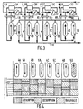
- the installation shown diagrammatically in FIG. 3 is of the modular type, that is to say it comprises several independent ozonization loops 1A to 1D. This has significant advantages from the point of view of reliability (arrangement of the loops in individual rooms facilitating loop-by-loop maintenance) and adaptation to variable ozone requirements. In addition, by coupling all the loops for desorption and sweeping, the number of adsorbent bottles is reduced from three to two for each loop, as follows.
- Each loop 1A to 1D comprises, as previously, respectively, a "Roots” compressor 2A to 2D, an ozonator 3A to 3D and a heat exchanger 8A to 8D.
- Each loop is associated with two bottles of silica gel 4A, 5A to 4D, 5 D.
- the collectors 9 and 10 can respectively be selectively connected to the upper inlet and to the lower inlet of each bottle, while the collector 11 is permanently connected, by four branches 11A to 11D, to the four loops 1A to 1D upstream compressor. This ensures a constant flow of oxygen in the compressor and in the ozonator.
- each bypass of the collector 11 supplying the four loops provides the loop comprising a scanning with a corresponding additional flow of oxygen.
- the upper inlet of each bottle can be connected by does not conduct such as 100 5D to the manifold 9 to recover the sweep rate in the carrier gas.
- the installation includes switching means (not shown) which ensure cyclic operation of all the bottles, as illustrated in FIG. 4: for a cycle of 8 minutes, each bottle successively performs a co-current adsorption phase of 4 minutes, a counter-current desorption phase of 3 minutes and a co-current scanning phase of one minute, the nitrogen and sweep flow rates being adapted accordingly.
- switching means (not shown) which ensure cyclic operation of all the bottles, as illustrated in FIG. 4: for a cycle of 8 minutes, each bottle successively performs a co-current adsorption phase of 4 minutes, a counter-current desorption phase of 3 minutes and a co-current scanning phase of one minute, the nitrogen and sweep flow rates being adapted accordingly.
- the following table summarizes this operation. In the boxes of this table, "A” denotes an adsorption phase, "D” denotes a desorption phase and "B" denotes a scanning phase.
- Bottle 1 3 4 5 6 7 8 Time (min) 1 AT D AT D AT B 2 AT B AT D AT D D AT 3 D AT AT B AT D D AT 4 D AT D AT B D AT 5 D AT D AT B AT 6 B AT D AT D AT AT D 7 AT D B AT D AT AT D 8 AT D AT D B AT D;
- n bottles are in the co-current adsorption phase
- (n - 1) bottles in the counter-current desorption phase and one bottle is in co-current scanning phase.
- the duration of the adsorption is taken as a unit, the duration of scanning is in principle 1 not and therefore the duration of desorption n-1 not .
- each ozonator treats 250 Nm 3 / h of oxygen, each loop permanently receives an additional 45/4 Nm 3 / h; and the sweep, which must be carried out for a period equal to a quarter of the adsorption time, consumes 45 Nm 3 / h, so that the corresponding bypass (here 11D) supplies the 1D loop with an oxygen supplement of 45 Mn 3 / h.
- This sweeping gas is recovered in the collector 9, and from each of the three bottles in desorption exits against the current a flow of 1000 3 Nm 3 / h of nitrogen-ozone mixture.
- the recovery of the scanning flow makes it possible to reduce the flow of carrier gas to be supplied. If it is impure nitrogen, as will be seen below in the case where the installation is coupled to an air separation device, it is the nitrogen flow rate which defines the size of this device. , and the gain, of the order of 5%, obtained on this speed reduces investment and energy. If the carrier gas is air, it must be dehydrated, which is expensive, and the aforementioned recovery also provides a gain.
- FIGS. 5A and 5B together represent a complete ozone production installation comprising on the one hand (FIG. 5A) an air separation device suitable for this application, and on the other hand (FIG. 5B) four loops arranged in the same as in Figure 3.
- the apparatus of FIG. 5A supplies the four loops of FIG. 5B with supplemental oxygen, via the collector 11, and the carrier nitrogen via the collector 9. It is also connected to the four loops by the production collector 10 carrying the nitrogen-ozone mixture. It provides all the gases and cold necessary for the production of ozone.
- This device comprises an air compressor 20, a device 21 for purifying the compressed air, a turbine 22 - booster 23 assembly, a heat exchange line 24 and a distillation column 25.
- the compressed air 4 bar by the compressor 20 then purified, is compressed to 5 bar by the blower 23 then is cooled from the temperature ambient in the exchange line 24.
- a significant portion, for example of the order of half, or even more, of the air flow is diverted before reaching the cold end of this exchange line and is turbinated in 22, which ensures the cold resistance of the installation as well as the mechanical drive of the booster 23.
- the turbine flow, expanded to 1.4 bar is introduced into an intermediate zone of the column 25.
- the rest of the air is cooled to approximately - 175 ° C, liquefied in a tank condenser-vaporizer 26 of the column then expanded to 1.4 ata and injected at the top of the latter.
- column 25 produces oxygen in the tank at a purity of between 95% and 99.5% and at the top a residual gas R consisting of nitrogen and 10 to 15% of oxygen. It is this gas which will constitute the carrier gas of the ozone and will be called “nitrogen” in the following for more convenience. This gas also contributes to the sub-cooling of the air in a heat exchanger 26 is associated with the column.
- the nitrogen drawn off at the head of the column is heated in the exchange line 24 against the flow of air to about -90 ° C. and then passes into the manifold 9.
- the nitrogen-ozone production mixture penetrates substantially. at the same level in the exchange line 24 and heats up against the air flow to room temperature, below about 1.1 ata. Part of the nitrogen, diverted in a pipe 27 before entering the exchange line, crosses it from end to end and is used for the regeneration of the adsorbent bottles of the purification device 21.
- the nitrogen collector 9 is in fact split into a first collector 9 1 and a second collector 9 2 .
- a bypass 9 1A heats the nitrogen to approximately - 80 ° C in the exchanger 8A against the current of the O 2 - O 3 mixture, then opens into the collector 9 2 , from which the nitrogen can be distributed in the three bottles in desorption (here 5A to 5C) by branches 9 2A to 9 2C ' then to come out again by branches 10A to 10C of the collector 10.
- the oxygen collector 11 has two branches: a branch 11 1 , controlled by a valve 28 with constant flow, from which four branches 11 1A , ... emerge in each loop just upstream of the corresponding compressor 2; and a branch 11 2 from which four branches 11 2A , .... controlled by valves 29A, ... leave, subject to the pressure of the corresponding loop and also opening just upstream of the corresponding compressor 2.
- the oxygen-ozone mixture leaving the ozonator 3A is cooled to - 90 ° C by crossing the end-to-end exchanger 8A against the current of nitrogen, crossing the bottle (here 4A) in adsorption, comes out towards - 80 ° C, enters at this temperature in the exchanger 8A, heats up there against the current of the oxygen-ozone mixture and returns to ambient temperature in the compressor 2A.
- the sweep flow is compensated by an equal flow injected into the loop by the corresponding bypass 11 1 (here 11 1D ), and any possible difference in flow rate is compensated by the intervention of the corresponding valve 29 (here 29D) which brings the pressure of the loop at the inlet of the compressor "Roots" back to the set value (here 2D).
- FIG. 5B also shows all of the connecting pipes and of the solenoid valves which allow the circulation of the gases and the permutation of the roles of the bottles, as explained above.
- an oxygen bypass 31 for each loop, an oxygen bypass 31; thanks to this, a flow of cold oxygen can avoid the exchanger 8A, ... in order to effect a temperature adjustment, this flow being controlled by the temperature of the nitrogen leaving the exchanger.
- the phase of desorption use either hotter nitrogen or nitrogen at lower pressure (relative to the pressure of the adsorption phase).
- the first solution is to be ruled out because of the short duration of the various phases, which does not allow to play on the temperatures; there therefore remains only the second solution, which can be achieved by increasing the operating pressure of the ozonizers, the desorption pressure being fixed by the pressure of use of the nitrogen-ozone mixture (here approximately 1.1 bar).
- adsorption pressure 1.1 to 2.5 ata and a desorption pressure of between 0.5 and 1.5 ata.
- Another possible advantage of desorption at a pressure lower than that of adsorption is a higher ozone concentration in the production gas R + O 3 appreciably increased in the inverse ratio of the absolute pressures.
- the collector 9 is not split; the nitrogen is simply reheated to approximately - 80 ° C in the exchanger 8 then sent to the bottle (here 6) in desorption, and the nitrogen-ozone mixture is recovered by the collector 10.
- the circulating oxygen-ozone mixture in the loop crosses the bottle in adsorption (here 4) and enters the exchanger 8 at the temperature level (approximately - 80 ° C) where the desorption nitrogen comes out, then is warmed up to room temperature and returned to compressor 2. It is the sweep flow derived from the loop which crosses the third bottle (here 5) via a manifold 32 and a bypass 32 5 and is recovered by a line 100 5 in the collector 9, downstream of the exchanger 8.
- the three lines 100 4 , 100 5 and 100 6 meet to form the recovery collector 100, controlled by the valve 30 at constant flow.
- the collector 11 has a single branch.
- the make-up oxygen leaves the exchange line 24 of FIG. 5A at the same temperature level as the nitrogen, that is to say approximately -90 ° C., as indicated in broken lines at 11 a in FIG. 5A, and is warmed to room temperature in the exchanger 8, against the current of the oxygen-ozone mixture, before being injected into the loop 1, via the valve 29 controlled by the pressure of this loop.
- the variant of FIG. 7 differs from the previous one in that the cooling of the oxygen-ozone mixture of loop 1 is entirely ensured against the current by the supplemental oxygen, which is brought by the manifold 11 in gaseous form. but at its dew point, that is to say approximately - 175 ° C., as indicated in phantom in 11b in FIG. 5A, or even in the liquid state, and injected into the loop at the cold end of the exchanger 8.
- the nitrogen is extracted from the exchange line 24 directly at the desorption temperature, ie approximately - 80 ° C.
- the cold gas was topped up not directly in the oxygen-ozone mixture before its introduction into the adsorber 4, but in the fluid leaving the latter, therefore in a fluid with very low ozone concentration.
- the process as described makes it possible to obtain, at a constant flow rate of substitution gas, a practically constant ozone content from the start to the end of the desorption phase, with however a slight regular drop in this content depending on the dimensioning of the adsorbers and the duration of the phases.
- the solution with n ozonization loops leads, due to the time lag of the desorption phase of the bottles of the different loops, to a reduction in the ratio n of the drop in ozone content. compared to a single loop installation.
- the process makes it possible to ensure this consistency of production by modulating the flow rate of substitution gas during the desorption phase so as to compensate for the slight drop in content by a substantially proportional increase in the flow rate.
- the ozone generator is acted on by varying the ozone content at an unchanged oxygen flow rate, the new steady state regime will be obtained with a substitution gas with modified ozone content, but at unchanged flow rate; the flow rate will only have been temporarily changed, while the ozone ballast corresponding to the new operating regime is reconstituted in the adsorbers.
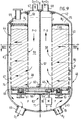
- the apparatus shown in Figures 8, 9 and 10 comprises an outer casing 40, consisting of a cylindrical shell 41 of vertical axis X - X and two domed upper 42 and lower 43 bottoms, in which is mounted coaxially a rotary assembly 44.
- the latter comprises a horizontal lower support 45 in the form of a circular plate, an annular upper cover 46 and two cylindrical grids, outer 47 and inner 48, between which is disposed an annular bed 49 of adsorbent material.
- the grid 47 connects the outer peripheries of the support 45 and the cover 46, while the grid 47 passes through the central opening of this cover and is guided in rotation at its upper end by a sealed bearing 50 secured to the bottom 42 of the envelope. .
- the two grids are perforated over their entire height except in their upper part, from a level situated a little below the cover 46.
- the support 45 is mounted on a circular bearing 51 with rollers carried by the lower bottom 43 of the casing by means of a metal frame 52 comprising a floor 53.
- the crew 44 can be rotated about the axis XX by a pinion 54 connected to a motor 55 inside the casing and attacking a ring gear 56 fixed under the support 45.
- a radial partition 57 divides the interior space of the grid 48 into two half-spaces 58, 59. This partition is fixed to the upper bottom 42 and rubs on the one hand, along its lower edge, on the support 45 by means of a sealing scraper 60, on the other hand, along each longitudinal edge , on the grid 48 by means of two sealing rakes 61, 62 (FIGS. 8 and 10).
- FIG. 8 there is provided, over the entire height of the crew 44, from the cover 46 to the fixed floor 53, two radial partitions (FIG. 8): a radial partition 63 coplanar with the partition 57, and another radial partition 64 angularly offset by an acute angle clockwise (considering FIG. 8) relative to location 76.
- Each of the partitions 63 and 64 is fixed by its outer edge to the ferrule 41 and rubs by a sealing scraper on the grid 47.
- two seals are provided, each extending in a horizontal plane over a little more than a semicircle, from the partition 63 to the partition 64.
- the upper seal 65 is fixed to the upper bottom. 42 of the envelope and rubs on the outer periphery of the cover 46, while the lower seal 66 is fixed on the upper face of the floor 53 and rubs on the outer periphery of the support 45.
- the top of the upper bottom 42 has two orifices 67,68 opening out inside the grid 48, on either side of the partition 57, while the lower bottom 43 has two orifices 69, 70 emerging under the support 45, on either side of a radial partition 71 which is part of the framework 52.
- the adsorbent bed 49 is moreover divided into multiple sectors 72 (thirty-two in number in the example shown) by radial plates 73 ( Figure 8) connecting the two grids.
- the space between the crew 44 and the envelope 40 is divided in leaktight fashion into a half-space 74 which communicates only with the orifice 69 and, through part of the sectors 72 of the adsorbent bed, with the orifice 67, and in a half-space 75 which communicates only with the orifice 70 and, through another part of the sectors 72, with the orifice 68.
- This device is used in the following manner to implement a process similar to that illustrated in phantom in Figure 1, the device replacing the three bottles illustrated in this figure.
- the orifice 67 is connected to the loop 1, downstream of the heat exchanger 8, so that it is permanently supplied with the oxygen-ozone mixture cooled by this exchanger.
- the orifice 68 is connected to the pipe of production gas 10.
- the orifice 69 is connected to the loop 1, upstream of the return to the exchanger 8.
- the orifice 70 is connected to the pipe 9 for supplying nitrogen.
- the crew 44 is rotated at constant speed clockwise in FIG. 8.
- the oxygen at the orifice 69 and the nitrogen at the orifice 70 are at substantially the same pressure P, for example slightly higher than atmospheric pressure; taking into account a pressure drop p, for example of the order of 30 mb, when crossing the bed 49, there will be a pressure P + p at the orifice 65 and P - p at the orifice 68, which imposes the directions of circulation of the gases.
- sector (s) 72 3 , 72 4 are in the co-current scanning phase (radially from the inside to the outside) by the oxygen-ozone mixture coming from the half space central 59 and the oxygen-nitrogen mixture which emerges therefrom reaches the outside half-space 75 and mixes with the nitrogen which feeds the latter to participate with this nitrogen in the desorption against the current of the N / 2 sectors comprised between the partition 63 and location 76.
- N sectors 72 we have N / 2 sectors in desorption, n sectors in scanning-adsorption (number of sectors between the partition 64 and the location 76) and (N / 2) - n sectors in adsorption.
- the installation thus permanently supplies a constant flow of mixture consisting essentially of nitrogen and ozone, without the need for a switching valve.
- the relative duration of each adsorption, desorption and scanning-adsorption phase can be adjusted by the choice of the angular offset between the partition 64 and the plane of the partitions 57 and 63, and the absolute duration of each phase by choosing the rotation speed of the crew 44.
- bearings 50 and 51 as well as the pinion 54 and its drive motor 55 are entirely contained in the half-space 75, and therefore under a nitrogen atmosphere, which is advantageous for their proper functioning and for safety. .
- FIG. 11 takes as an example the diagram of FIG. 6, with the same reference numbers, but uses l the rotary absorbent bed apparatus as explained above.
- an annular bed adsorbent 49 delimited by two external 47 and internal 48 grids is divided into N sectors 72 by radial plates 73 extending between these two grids, and each of these sectors is placed successively in communication with a supply of oxygen-ozone mixture , with a supply of nitrogen and with a supply of a purging gas which is, in the example shown, oxygen.
- the essential difference lies in the fact that, now, the bed 49 is fixed while the apparatus comprises a rotating core, constituting the rotary assembly 44, which ensures the desired distribution of the three gases between the sectors 72.
- the casing 40 has in its lower part a double bottom 77 converging downwards which ends, at its lower end, by an open cylinder 78.
- a tube constituting the orifice 69 starts radially from this cylinder and crosses at tight seal the ferrule 41, and two annular seals 79 are fixed in the cylinder 78, above and below this tubing.
- the orifice 70 opens into the space between the lower bottom 43 and the double bottom 77.
- the two grids 47 and 48 are connected at their top by the upper bottom 42 and at their base by the support 45, which is here roughly frustoconical and parallel to the double bottom 77.
- the inner grid 48 extends downwards until to the cylinder 78, and an annular seal 80 is fixed in the grid 47 at the connection between the latter and the support 45.
- the plates 73 extend outwards to the bottom 42, at the ferrule 41 and the double bottom 77, so that it is all the space delimited by the grid 47, the bottom 42, the ferrule 41 and the double bottom 77 which is divided into N sectors, as seen in the figures 13 and 14.
- the envelope 40 has at its top an opening 81 of the same diameter as the grid 48 and on which is fixed a cylindrical dome 82 of the same diameter, closed at its top and open at its base.
- Two annular seals 83 are fixed in the dome respectively between the two pipes 67 and 68 and below tubing 67.
- the rotating core 44 is guided by an upper bearing 84 provided at the top of the dome 82 and by a lower bearing 85 provided at the bottom point 83. It is rotated by a motor 55 fixed to the bottom 43, inside the casing 40, by means of an endless screw 86 which attacks a toothed wheel 87 secured to the core.
- the core 44 comprises a cylindrical plug open at its two ends.
- the upper plug 88 cooperates by its end parts with the two seals 83 and has between them a semicircular slot 89 whose upper edge is connected to the periphery of a horizontal plate 90 in the shape of a semi-moon ( Figure 15 ).
- a diametral vertical partition 57 extends downward, the width of which is equal to the internal diameter of the plug 88.
- the partition 57 Over the entire height of the grid 48, the partition 57 carries two wipers 61, 62 which rub on this grid (FIG. 13) so as to delimit two interior half-spaces 58 and 59.
- the partition 57 carries a shutter 91 in the form of an inverted cup 91 whose peripheral wall cooperates with the seal 80.
- the lower plug 92 cooperates by its end parts with the two seals 79 and has between them a slot 93 whose lower edge is connected to the periphery of a horizontal plate 94 located directly above the plate 90.
- a partition 95 forming a dihedral of the same angle, extends vertically between these spokes and the underside of the shutter 91. Between the upper seal 79 and the seal 80, this partition 95 rubs by its two edges, provided with scrapers seal, on the lower extension of the grille 48.
- Each plug 88, 92 delimits an annular space, respectively 96, 97, with the cylindrical wall 82, 78 which surrounds it.
- the orifices 67 to 70 are connected as in FIGS. 8 to 11, and the core 44 is driven in clockwise rotation in FIGS. 13 and 14.
- the oxygen-ozone mixture arrives through the tube 67 and enters the space 59 through slot 89 and possibly the space 96. From there, this mixture crosses N / 2 sectors 72 1 (FIG. 13), and oxygen comes out in the corresponding compartments 98 located outside the grid 47.
- a part of the oxygen crosses back in the opposite direction, that is to say towards the axis XX, n sectors 72 3 and 72 4 (FIG. 13), and the main part of the oxygen leaves via the tube 69 via the slot 93, and possibly the annular space 97, of the lower plug 92.
- the nitrogen introduced through the tube 70 crosses the plug 92 from bottom to top, enters the (N / 2) - n compartments 98 remaining and, from there, crosses the corresponding sectors 72 2 towards the axis XX, for evacuate through tubing 68 in the form of a nitrogen-ozone mixture (with a little oxygen), after passing from bottom to top the top plug 88.
- each sector 72 successively undergoes a phase of adsorption of ozone from the oxygen-ozone mixture, a phase of desorption against the current by nitrogen and a phase co-current scanning with oxygen, this oxygen then participating in the desorption and being found in the production gas consisting essentially of nitrogen and ozone.
- FIG. 17 illustrates a device quite similar to that of FIGS. 12 to 16 but which differs from it only in that the adsorbent bed 49 is of the "flat" type, that is to say axial flow, instead of the radial flow type.
- the apparatus is modified in the following way: the external grid 47 is removed, and the support 45 is replaced by a horizontal support grid 45 A extending from the grid 48, at the joint 80, up to to the ferrule 41.
- the bed 49 extends approximately to the top of the latter and, over the entire height of this bed, the grid 48 is full.
- the apparatus operates in the same manner as that of FIGS. 12 to 16, except that the gases pass vertically through the bed 49.
- FIGS. 8 to 10 can be applied to the case of a "flat" adsorbent bed, as shown in FIGS. 18 to 20.
- the rotary assembly 44 comprises two cylindrical sheets 47 A, 48 A, delimiting an annular space in which the adsorbent bed 49 is arranged, which fills it up to a short distance from its top.
- This annular space is closed at its base by a support grid 45 A and is open upwards.
- the space inside the interior sheet 48 A is closed at its two ends by solid discs upper 99 and lower 100.
- annular space containing the bed 49 is as previously divided into N sectors 72 by radial plates 73 extending over its entire height and from one sheet to another.
- a rounded 101 (FIG. 20) which gives it a T-section.
- the crew 44 rests on a circular bearing 51, at least one of the rollers of which is driven by a non-motor represented.
- the orifices 67 and 68 open on either side of the partition 103, while the orifices 69 and 70 open on either side of the partition 105.
- the crew 44 is rotated clockwise.
- the oxygen-ozone mixture enters through the orifice 67 in the device, crosses from top to bottom N / 2 sectors 72 1 in the adsorption phase and essentially leaves through the orifice 69 in the form of pure oxygen.
- the nitrogen enters through the orifice 70, crosses from bottom to top (N / 2) - n sectors 72 2 in the desorption phase and leaves through the orifice 68 in the form of the production mixture consisting essentially of nitrogen and ozone.
- Part of the oxygen is returned from bottom to top through the n remaining sectors 72 3 , 72 4 , to complete the desorption of these sectors and to carry out the scanning.
- the space containing nitrogen is adjacent to that containing oxygen, these two spaces (for example spaces 75 and 74 of Figures 8 to 10) being at substantially the same pressure P.
- these two spaces respectively containing the oxygen-ozone mixture and the production mixture, are adjacent to each other, the first (space 59 in FIGS. 8 to 10) being at the maximum pressure P + p and the second (space 58 of Figures 8 to 10) being at the minimum pressure Pp.
Landscapes
- Chemical & Material Sciences (AREA)
- Organic Chemistry (AREA)
- Chemical Kinetics & Catalysis (AREA)
- Physics & Mathematics (AREA)
- Fluid Mechanics (AREA)
- Inorganic Chemistry (AREA)
- Oxygen, Ozone, And Oxides In General (AREA)
- Separation Of Gases By Adsorption (AREA)
- Pharmaceuticals Containing Other Organic And Inorganic Compounds (AREA)
- Separation By Low-Temperature Treatments (AREA)
- Lubricants (AREA)
- Fats And Perfumes (AREA)
- Treating Waste Gases (AREA)
Claims (18)
- Verfahren zur Herstellung von Ozon des Typs, in welchem der in einem Ozonisierungskreislauf (1) zirkulierende Sauerstoff in einem Ozonisator (3) teilweise ozonisiert und das Ozon danach durch Adsorption aufgenommen und von einem Austauschgas desorbiert wird, dadurch gekennzeichnet, daß das Sauerstoff-Ozon-Gemisch im Gleichstrom durch eine erste Adsorbensmasse (4; 721), worin das Ozon adsorbiert wird, und gleichzeitig durch eine zweite Adsorbensmasse (6; 722) ein Strom eines Austauschgases, das zum Desorbieren der zweiten Masse dient, im Gegenstrom geführt und gleichzeitig eine dritte Adsorbensmasse (5; 723, 724) gespült wird, indem man diese dritte Adsorbensmasse von einem Spülgasstrom durchströmen läßt, der aus einem Teil des Sauerstoff-Ozon-Gemischs besteht, der dem Kreislauf (1) entnommen worden ist, wobei dieses Spülgas im Gleichstrom durch die dritte Adsorbensmasse (5; 723, 724) zirkuliert, und daß das Spülgas, das die dritte Adsorbensmasse (5; 723, 724) durchströmt hat, dem Austauschgas zugesetzt wird, bevor dieses in die zweite Adsorbensmasse (6; 722) eintritt, wobei jede Adsorbensmasse (4 bis 6; 721 bis 724) nacheinander von dem Sauerstoff-Ozon-Gemisch, dem Austauschgas und dem Spülgas durchströmt wird.
- Verfahren zur Herstellung von Ozon nach Anspruch 1 des Typs, worin in wenigstens einem Ozonisierungskreislauf (1; 1A ... 1D) der Sauerstoff in einem Ozonisator (3) teilweise ozonisiert und danach das Ozon in der Kälte durch Adsorption aufgenommen und von einem Austauschgas desorbiert wird, dadurch gekennzeichnet, daß der zu ozonisierende Sauerstoff und ein Restgas durch Luftdestillation erzeugt werden und daß das Restgas als Austauschgas und wenigstens eines der beiden Gase zur zusätzliches Bereitstellung der Kälte verwendet wird, die erforderlich ist, um das Sauerstoff-Ozon-Gemisch auf kalte Adsorptionstemperatur zu bringen.
- Verfahren nach Anspruch 2, dadurch gekennzeichnet, daß man die gesamte erforderliche Kälte erzeugt, indem in einer Turbine (22) ein großer Teil, insbesondere wenigstens die Hälfte, des Durchsatzes der Luft vor deren Destillation entspannt und die so entstehende mechanische Energie zur Vervollständigung der Luftverdichtung genutzt wird.
- Verfahren nach einem der Ansprüche 1 bis 3, dadurch gekennzeichnet, daß ein Durchsatz des Austauschgases eingesetzt wird, der dieselbe Größenordnung wie der des Sauerstoff-Ozon-Gemisches hat.
- Verfahren nach einem der Ansprüche 1 bis 4, dadurch gekennzeichnet, daß das Austauschgas zur Desorption bei einer Temperatur eingesetzt wird, die etwas über der Adsorptionstemperatur liegt.
- Verfahren nach einem der Ansprüche 1 bis 5, dadurch gekennzeichnet, daß das Austauschgas zur Desorption bei einem Druck eingesetzt wird, der unter dem Adsorptionsdruck liegt.
- Verfahren nach einem der Ansprüche 1 bis 6, dadurch gekennzeichnet, daß man während der Desorptionsphase den Durchsatz des Austauschgases derart verändert, daß die an den Verbraucher gelieferte Ozonmenge im wesentlichen konstant bleibt.
- Verfahren nach einem der Ansprüche 1 bis 7, dadurch gekennzeichnet, daß man, um unmittelbar auf einen veränderten Ozonbedarf zu reagieren, sofort im gleichen Sinn auf den Durchsatz des Austauschgases einwirkt.
- Verfahren zur Herstellung von Ozon nach einem der vorhergehenden Ansprüche mit n Ozonisierungskreisläufen (1A ... 1D) des Typs, in welchem in jedem Kreislauf der Sauerstoff in einem Ozonisator (3) teilweise ozonisiert und das Ozon danach durch Adsorption aufgenommen und von einem Austauschgas desorbiert wird, dadurch gekennzeichnet, daß man in jedem Kreislauf zwei Adsorptionskolonnen (4A, 5A ... 4D, 5D) auf folgende Weise einsetzt: Das Sauerstoff-Ozon-Gemisch wird abgekühlt und im Gleichstrom durch eine Adsorptionskolonne (4) geleitet, worin das Ozon adsorbiert wird, danach wird durch dieselbe Kolonne im Gegenstrom ein Austauschgasstrom geleitet und anschließend gespült, indem man diese Kolonne von einem Spülgasstrom durchströmen läßt, der aus einem Teil des Sauerstoff-Ozon-Gemischs besteht, der dem Kreislauf entnommen worden ist, wobei dieses Spülgas im Gleichstrom zirkuliert, und daß sich in wenigstens einem Teil jedes n-ten Zyklus gleichzeitig eine Kolonne (4A, ... 4D) jedes Kreislaufs in einer Adsorptionsphase im Gleichstrom, eine Kolonne (5A, 5B, 5C) der (n-1)-ten Kreisläufe (1A, 1B, 1C) in der Desorptionsphase im Gegenstrom und die übrige Kolonne (5D) des N-ten Kreislaufs (1D) in der Spülphase mit einem Strom des Spülgases befindet, der dem n-ten Kreislauf entnommen ist und im Gleichstrom zirkuliert.
- Verfahren nach Anspruch 9, dadurch gekennzeichnet, daß die Desorptions- und die Spülzeit jeder Kolonne (4A, 5A ... 4D, 5D) (n - 1)/n bzw. 1/n, bezogen auf die als Einheit genommene Adsorptionszeit, beträgt.
- Vorrichtung zur Durchführung des Verfahrens nach einem der Ansprüche 1 bis 8, dadurch gekennzeichnet, daß sie- einen Mantel (40), der ein ringförmiges Bett (49), das in eine bestimmte Anzahl Sektoren (72) eingeteilt ist, aus einem Adsorbens enthält,- Zwischenwände (53, 57, 63 bis 66, 71; 57, 88, 91, 92; 95, 102, 103, 105), die vier Zwischenräume (59, 74, 75, 58) begrenzen, die jeweils mit einer ersten Öffnung (67) für den Eintritt des Sauerstoff-Ozon-Gemisches, einer zweiten Öffnung (69) für den Sauerstoffausgang, einer dritten Öffnung (70) für den Eintritt des Austauschgases und einer vierten Öffnung (68) für den Ausgang des Produktgases, das im wesentlichen aus Austauschgas und Ozon besteht, in Verbindung stehen, wobei diese Zwischenwände die zweite Öffnung (69) mit der gegenüber der Adsorption stromabwärtigen Seite einer ersten Gruppe (721) von Sektoren, die erste Öffnung (67) mit der gegenüber der Adsorption stromaufwärtigen Seite einer zweiten Gruppe (721, 723, 724) von Sektoren, die aus der ersten Gruppe (721) und einer an diese erste Gruppe angrenzenden dritten Gruppe (723, 724) von Sektoren besteht, die vierte Öffnung (68) mit der gegenüber der Desorption im Gegenstrom stromabwärtigen Seite einer vierten Gruppe (722) von Sektoren, die aus den übrigen Sektoren besteht, und die dritte Öffnung (70) mit der gegenüber der Desorption stromaufwärtigen Seite der dritten und vierten Gruppe (722, 723, 724) von Sektoren kommunizieren lassen, und- Mittel (51, 55), um zwischen dem ringförmigen Bett (49) und den Zwischenwänden eine relative Drehung in einer solchen Richtung ausführen zu können, daß jeder Sektor (72) nacheinander und zyklisch Teil der ersten, vierten und dritten Gruppe wird,umfaßt.
- Vorrichtung nach Anspruch 11, dadurch gekennzeichnet, daß das Adsorbensbett (49) im Mantel (40) drehbar angebracht ist, während die Zwischenwände fest sind.
- Vorrichtung nach Anspruch 11, dadurch gekennzeichnet, daß das Adsorbensbett (49) fest ist, während die Zwischenwände drehbar im Mantel (40) angebracht sind.
- Vorrichtung nach Anspruch 13, dadurch gekennzeichnet, daß die Zwischenwände einen im Zentrum des Adsorbensbetts (49) angeordneten, sich drehenden Kern (44) bilden, der zwei abgestufte Rohre (88, 92) enthält.
- Vorrichtung nach einem der Ansprüche 11 bis 14, dadurch gekennzeichnet, daß das Adsorbensbett (49) radial durchströmt wird.
- Vorrichtung nach einem der Ansprüche 11 bis 14, dadurch gekennzeichnet, daß das Adsorbensbett (49) axial durchströmt wird.
- Vorrichtung nach einem der Ansprüche 11 bis 16, dadurch gekennzeichnet, daß sich die Mittel (51, 54 bis 56) für den Drehantrieb vollständig in demselben Zwischenraum (75) des Mantels (40) befinden, der das Austauschgas enthält.
- Vorrichtung nach einem der Ansprüche 11 bis 17, dadurch gekennzeichnet, daß die Zwischenräume (58, 59), die jeweils mit der vierten Öffnung (68) bzw. der ersten Öffnung (67) in Verbindung stehen, wie die beiden anderen Zwischenräume (74, 75) aneinander angrenzen.
Priority Applications (1)
| Application Number | Priority Date | Filing Date | Title |
|---|---|---|---|
| AT86902421T ATE43823T1 (de) | 1985-04-16 | 1986-04-15 | Verfahren und vorrichtung zur erzeugung von ozon. |
Applications Claiming Priority (3)
| Application Number | Priority Date | Filing Date | Title |
|---|---|---|---|
| FR8505699A FR2580271B1 (fr) | 1985-04-16 | 1985-04-16 | Procede de production d'ozone |
| FR8505699 | 1985-04-16 | ||
| PCT/FR1986/000126 WO1986006056A1 (fr) | 1985-04-16 | 1986-04-15 | Procede et appareil de production d'ozone |
Publications (3)
| Publication Number | Publication Date |
|---|---|
| EP0218660A1 EP0218660A1 (de) | 1987-04-22 |
| EP0218660B1 EP0218660B1 (de) | 1989-06-07 |
| EP0218660B2 true EP0218660B2 (de) | 1996-08-07 |
Family
ID=9318272
Family Applications (1)
| Application Number | Title | Priority Date | Filing Date |
|---|---|---|---|
| EP86902421A Expired - Lifetime EP0218660B2 (de) | 1985-04-16 | 1986-04-15 | Verfahren und vorrichtung zur erzeugung von ozon |
Country Status (16)
| Country | Link |
|---|---|
| US (2) | US4786489A (de) |
| EP (1) | EP0218660B2 (de) |
| JP (1) | JP2562815B2 (de) |
| KR (1) | KR930006688B1 (de) |
| AT (1) | ATE43823T1 (de) |
| BR (1) | BR8606627A (de) |
| DE (1) | DE3663794D1 (de) |
| ES (1) | ES8708199A1 (de) |
| FI (1) | FI78441C (de) |
| FR (1) | FR2580271B1 (de) |
| MX (1) | MX170450B (de) |
| NO (1) | NO167275C (de) |
| NZ (1) | NZ215839A (de) |
| PT (1) | PT82371B (de) |
| WO (1) | WO1986006056A1 (de) |
| ZA (1) | ZA862817B (de) |
Families Citing this family (43)
| Publication number | Priority date | Publication date | Assignee | Title |
|---|---|---|---|---|
| AT392256B (de) * | 1989-06-26 | 1991-02-25 | Voest Alpine Ind Anlagen | Verfahren zur herstellung von sauerstoff und/oder ozon |
| FR2667801B1 (fr) * | 1990-10-11 | 1992-12-04 | Air Liquide | Procede et equipement de separation par adsorption d'au moins un constituant d'un melange gazeux. |
| GB9207298D0 (en) * | 1992-03-31 | 1992-05-13 | Boc Group Plc | Treating materials with ozone |
| BE1005764A3 (nl) * | 1992-04-15 | 1994-01-18 | Atlas Copco Airpower Nv | Inrichting voor het drogen van een gas. |
| CA2136265C (en) * | 1993-11-22 | 1999-07-27 | Masami Shimizu | Apparatus for generating and condensing ozone |
| FR2728554B1 (fr) | 1994-12-27 | 1997-06-20 | Air Liquide | Procede et dispositif de traitement d'un melange gazeux comprenant de l'ozone |
| WO1996024554A1 (en) * | 1995-02-06 | 1996-08-15 | Nippon Sanso Corporation | Ozone enriching method |
| US5807422A (en) * | 1995-03-03 | 1998-09-15 | Grgich; George R. | Divided radial and spherical desiccant bed adsorption units |
| US5632802A (en) * | 1995-03-03 | 1997-05-27 | Grgich; George R. | Apparatus and method of regenerating adsorbers for drying air |
| US5810910A (en) * | 1995-10-06 | 1998-09-22 | Air Products And Chemicals, Inc. | Adsorbents for ozone recovery from gas mixtures |
| JP3980091B2 (ja) * | 1996-03-01 | 2007-09-19 | 三菱電機株式会社 | オゾン貯蔵装置 |
| US5759242A (en) * | 1996-07-23 | 1998-06-02 | Praxair Technology, Inc. | Radial bed vaccum/pressure swing adsorber vessel |
| US5846298A (en) * | 1997-05-09 | 1998-12-08 | Air Products And Chemicals, Inc. | Ozone recovery by zeolite adsorbents |
| US6193852B1 (en) | 1997-05-28 | 2001-02-27 | The Boc Group, Inc. | Ozone generator and method of producing ozone |
| GB9712165D0 (en) * | 1997-06-11 | 1997-08-13 | Air Prod & Chem | Processes and apparatus for producing a gaseous product |
| AU752114B2 (en) * | 1997-12-01 | 2002-09-05 | Air Products And Chemicals, Inc. | Modular pressure swing adsorption apparatus |
| US7094275B2 (en) * | 1997-12-01 | 2006-08-22 | Questair Technologies, Inc. | Modular pressure swing adsorption apparatus |
| JPH11335102A (ja) * | 1998-05-22 | 1999-12-07 | Iwatani Internatl Corp | 高濃度オゾン連続発生方法及びその装置 |
| AU5466400A (en) * | 1999-06-04 | 2000-12-28 | Flair Corporation | Rotating drum adsorber process and system |
| CA2274318A1 (en) * | 1999-06-10 | 2000-12-10 | Questor Industries Inc. | Pressure swing adsorption with axial or centrifugal compression machinery |
| RU2179149C2 (ru) * | 1999-08-04 | 2002-02-10 | Открытое акционерное общество криогенного машиностроения | Способ получения озоногазовой смеси и устройство для его осуществления |
| US6136284A (en) * | 1999-12-09 | 2000-10-24 | The Boc Group, Inc. | Process for the removal of nitrogen oxides from gas streams |
| JP2001248794A (ja) | 2000-03-02 | 2001-09-14 | Kansai Electric Power Co Inc:The | オゾン貯蔵方法および装置 |
| US6585805B1 (en) * | 2001-12-13 | 2003-07-01 | General Motors Corporation | Gas stream apparatus and method |
| ATE530242T1 (de) | 2003-07-18 | 2011-11-15 | David Richard Hallam | Luftbehandlungsvorrichtung |
| US7392657B2 (en) * | 2004-06-09 | 2008-07-01 | American Air Liquide, Inc. | Methods of dissolving ozone in a cryogen |
| FR2873750B1 (fr) * | 2004-08-02 | 2009-04-17 | Inst Francais Du Petrole | Dispositif pour la production d'un gaz chaud par oxydation utilisant un reacteur rotatif simule |
| US7491261B2 (en) | 2005-06-27 | 2009-02-17 | Wearair Oxygen, Inc. | Process and apparatus for generating and delivering an enriched gas fraction |
| US20080028933A1 (en) * | 2006-08-07 | 2008-02-07 | Ross David A | Radial sieve module |
| JP5492566B2 (ja) * | 2007-11-30 | 2014-05-14 | 東芝三菱電機産業システム株式会社 | 高濃度オゾンガス生成装置および高濃度オゾンガス生成方法 |
| US8029603B2 (en) | 2009-01-23 | 2011-10-04 | Air Products And Chemicals, Inc. | Pressure swing adsorption cycle for ozone production |
| US8182772B2 (en) * | 2009-06-26 | 2012-05-22 | Leon Yuan | Radial flow continuous reaction/regeneration apparatus |
| FR2963417B1 (fr) * | 2010-08-02 | 2014-03-28 | Air Liquide | Vaporiseur a tubes en forme de u |
| US8840705B2 (en) * | 2011-07-07 | 2014-09-23 | Linde Aktiengesellschaft | Methods for the ozonolysis of organic compounds |
| US8808426B2 (en) * | 2012-09-04 | 2014-08-19 | Exxonmobil Research And Engineering Company | Increasing scales, capacities, and/or efficiencies in swing adsorption processes with hydrocarbon gas feeds |
| DE102014218344B4 (de) * | 2014-09-12 | 2023-08-03 | Dürr Systems Ag | Verfahren und Anlage zum Abtrennen von Verunreinigungen aus Prozessabluft |
| FR3033264B1 (fr) * | 2015-03-05 | 2017-03-03 | Ifp Energies Now | Reacteur radial a lits catalytiques fixes |
| WO2017044684A1 (en) * | 2015-09-10 | 2017-03-16 | Linde Aktiengesellschaft | Methods for separating ozone |
| DE102016210224A1 (de) * | 2016-06-09 | 2017-12-14 | Friedrich-Alexander-Universität Erlangen-Nürnberg | Reaktor und Verfahren zur Umsetzung von gleichgewichtslimitierten Reaktionen |
| WO2018026517A1 (en) | 2016-08-04 | 2018-02-08 | Exxonmobil Research And Engineering Company | Increasing scales, capacities, and/or efficiencies in swing adsorption processes with hydrocarbon gas feeds |
| US10695710B2 (en) * | 2018-08-02 | 2020-06-30 | Messer Industries Usa, Inc. | Methods for producing ozone and oxygen mixtures |
| US10730004B2 (en) | 2018-08-03 | 2020-08-04 | Messer Industries Usa, Inc. | Recovery of oxygen used in ozone production |
| FR3114519B1 (fr) * | 2020-09-29 | 2022-08-26 | Commissariat Energie Atomique | Reacteur tubulaire a lit fixe |
Family Cites Families (36)
| Publication number | Priority date | Publication date | Assignee | Title |
|---|---|---|---|---|
| US2630191A (en) * | 1946-10-28 | 1953-03-03 | Jefferson Lake Sulphur Co | Cyclic adsorption process |
| US2799362A (en) * | 1956-10-19 | 1957-07-16 | Jefferson Lake Sulphur Co | Cyclic adsorption process |
| DE1181674B (de) * | 1959-01-05 | 1964-11-19 | Dr Josef Heyes | Vorrichtung zur Trennung von Gas- oder Fluessigkeitsgemischen |
| SE332052B (de) * | 1967-07-20 | 1971-01-25 | Munters C | |
| US3504483A (en) * | 1967-09-08 | 1970-04-07 | Hitachi Ltd | Apparatus for the removal of sulfur oxides from waste gases |
| US3607133A (en) * | 1968-10-23 | 1971-09-21 | Kachita Co Ltd | Apparatus for removing carbon monoxide from room air and exhaust gas |
| SE368662B (de) * | 1972-03-10 | 1974-07-15 | Munters Ab Carl | |
| GB1451645A (de) * | 1973-12-20 | 1976-10-06 | ||
| JPS50116389A (de) * | 1973-12-29 | 1975-09-11 | ||
| JPS5239793B2 (de) * | 1973-12-29 | 1977-10-07 | ||
| US3921002A (en) * | 1974-04-22 | 1975-11-18 | Martin Marietta Corp | Ozone generator |
| JPS5167266A (en) * | 1974-12-09 | 1976-06-10 | Daikin Ind Ltd | Chitsuso sansokongogasuhatsuseisochi |
| US3963625A (en) * | 1975-03-12 | 1976-06-15 | W. R. Grace & Co. | Ozone generation and recovery system |
| JPS539290A (en) * | 1976-07-13 | 1978-01-27 | Mitsubishi Electric Corp | Ozone supplier |
| JPS5813483B2 (ja) * | 1976-10-28 | 1983-03-14 | 三菱電機株式会社 | 酸素リサイクルオゾン発生装置 |
| DE2706992C3 (de) * | 1977-02-18 | 1981-08-06 | Hoechst Ag, 6000 Frankfurt | Verfahren zur Bestimmung des Ozongehaltes von Gasgemischen |
| JPS5925724B2 (ja) * | 1977-06-14 | 1984-06-20 | 石川島播磨重工業株式会社 | 連続式オゾン添加装置 |
| US4143118A (en) * | 1977-08-08 | 1979-03-06 | Xerox Corporation | Apparatus and method for ozone reduction in electrostatographic reproduction equipment |
| US4421533A (en) * | 1978-03-27 | 1983-12-20 | Takeda Chemical Industries, Ltd. | Method of removing ozone and composition therefor |
| JPS54130493A (en) * | 1978-03-31 | 1979-10-09 | Sumitomo Precision Prod Co | Ozonizer |
| JPS54134091A (en) * | 1978-04-11 | 1979-10-18 | Kiyoshi Fukui | Ozoneecontaining gas manufacturing method and apparatus |
| JPS5547202A (en) * | 1978-09-29 | 1980-04-03 | Osaka Oxgen Ind Ltd | Treating method for ozone contained in gas |
| DE2854060A1 (de) * | 1978-12-14 | 1980-07-03 | Linde Ag | Verfahren zum bereitstellen eines einsatzgases fuer eine chemische reaktion und zum abtrennen eines gasfoermigen reaktionsproduktes |
| JPS55158107A (en) * | 1979-05-29 | 1980-12-09 | Mitsubishi Electric Corp | Oxygen recycling type ozone generating apparatus |
| US4240798A (en) * | 1979-07-05 | 1980-12-23 | Aga Aktiebolag | Method and apparatus for reducing ozone |
| US4388274A (en) * | 1980-06-02 | 1983-06-14 | Xerox Corporation | Ozone collection and filtration system |
| US4324564A (en) * | 1980-07-07 | 1982-04-13 | Near Equilibrium Research Associates | Adsorption beds and method of operation thereof |
| DE3132758A1 (de) * | 1981-08-19 | 1983-03-03 | Linde Ag, 6200 Wiesbaden | Absorptionsverfahren |
| JPS5925724A (ja) * | 1982-08-04 | 1984-02-09 | オリンパス光学工業株式会社 | 内視鏡插入部の先端部 |
| DE3230922A1 (de) * | 1982-08-20 | 1984-02-23 | Messer Griesheim Gmbh, 6000 Frankfurt | Verfahren zur behandlung von stoffen mit ozon |
| US4589892A (en) * | 1983-04-07 | 1986-05-20 | Bry-Air, Inc. | Sequenced modular bed carousel dehumidifier |
| US4764276A (en) * | 1984-07-30 | 1988-08-16 | Advanced Separation Technologies Incorporated | Device for continuous contacting of fluids and solids |
| US4522726A (en) * | 1984-07-30 | 1985-06-11 | Progress Equities Incorporated | Advanced separation device and method |
| DE3434169C2 (de) * | 1984-09-18 | 1987-01-02 | Messer Griesheim Gmbh, 6000 Frankfurt | Verfahren zur Gewinnung von Ozon |
| US4617182A (en) * | 1985-08-26 | 1986-10-14 | Air Products And Chemicals, Inc. | Cascade heat recovery with coproduct gas production |
| US4619821A (en) * | 1985-12-02 | 1986-10-28 | Amoco Corporation | Ozone decomposition |
-
1985
- 1985-04-16 FR FR8505699A patent/FR2580271B1/fr not_active Expired - Lifetime
-
1986
- 1986-04-11 ES ES553897A patent/ES8708199A1/es not_active Expired
- 1986-04-11 PT PT82371A patent/PT82371B/pt not_active IP Right Cessation
- 1986-04-15 BR BR8606627A patent/BR8606627A/pt unknown
- 1986-04-15 KR KR1019860700890A patent/KR930006688B1/ko not_active Expired - Fee Related
- 1986-04-15 AT AT86902421T patent/ATE43823T1/de not_active IP Right Cessation
- 1986-04-15 JP JP61502249A patent/JP2562815B2/ja not_active Expired - Lifetime
- 1986-04-15 NZ NZ215839A patent/NZ215839A/xx unknown
- 1986-04-15 ZA ZA862817A patent/ZA862817B/xx unknown
- 1986-04-15 WO PCT/FR1986/000126 patent/WO1986006056A1/fr not_active Ceased
- 1986-04-15 US US06/940,812 patent/US4786489A/en not_active Expired - Fee Related
- 1986-04-15 DE DE8686902421T patent/DE3663794D1/de not_active Expired
- 1986-04-15 MX MX002175A patent/MX170450B/es unknown
- 1986-04-15 EP EP86902421A patent/EP0218660B2/de not_active Expired - Lifetime
- 1986-12-11 NO NO864998A patent/NO167275C/no unknown
- 1986-12-11 FI FI865064A patent/FI78441C/fi not_active IP Right Cessation
-
1988
- 1988-08-09 US US07/230,153 patent/US4863497A/en not_active Expired - Fee Related
Also Published As
| Publication number | Publication date |
|---|---|
| EP0218660A1 (de) | 1987-04-22 |
| PT82371A (fr) | 1986-05-01 |
| KR870700221A (ko) | 1987-05-30 |
| NO864998L (no) | 1986-12-11 |
| NO167275C (no) | 1991-10-23 |
| FI78441C (fi) | 1989-08-10 |
| FI78441B (fi) | 1989-04-28 |
| JP2562815B2 (ja) | 1996-12-11 |
| WO1986006056A1 (fr) | 1986-10-23 |
| BR8606627A (pt) | 1987-08-04 |
| KR930006688B1 (ko) | 1993-07-22 |
| PT82371B (pt) | 1992-07-31 |
| US4786489A (en) | 1988-11-22 |
| US4863497A (en) | 1989-09-05 |
| MX170450B (es) | 1993-08-23 |
| FR2580271A1 (fr) | 1986-10-17 |
| JPS62502682A (ja) | 1987-10-15 |
| NO167275B (no) | 1991-07-15 |
| FI865064A0 (fi) | 1986-12-11 |
| ES553897A0 (es) | 1987-10-01 |
| ZA862817B (en) | 1986-11-26 |
| DE3663794D1 (en) | 1989-07-13 |
| FI865064L (fi) | 1986-12-11 |
| ES8708199A1 (es) | 1987-10-01 |
| ATE43823T1 (de) | 1989-06-15 |
| NZ215839A (en) | 1989-07-27 |
| EP0218660B1 (de) | 1989-06-07 |
| FR2580271B1 (fr) | 1994-07-08 |
Similar Documents
| Publication | Publication Date | Title |
|---|---|---|
| EP0218660B1 (de) | Verfahren und vorrichtung zur erzeugung von ozon | |
| EP0480840B1 (de) | Verfahren und Vorrichtung zur Abtrennung durch Adsorption von mindestens einem Bestandteil einer Gasmischung | |
| EP0655941A1 (de) | Verfahren und vorrichtung zur trennung von gaskomponenten durch adsorption | |
| EP2129449B1 (de) | Verfahren und vorrichtung zur reinigung oder trennung mit mehreren phasenverschobenen adsorptionseinheiten | |
| EP0071553B1 (de) | Verfahren und Vorrichtung zur Reinigung von Helium in einer Gasmischung | |
| WO2005000447A1 (fr) | Procede de prepurification d'air par cycle tsa accelere | |
| EP2654925B1 (de) | Abschliessendes reinigungsverfahren für biogas | |
| US4350500A (en) | Process and apparatus for separating gaseous component from a mixture | |
| EP3174618A1 (de) | Adsorber mit rotierendem trockner | |
| FR2651149A1 (fr) | Procede continu et dispositif de separation chromatographique d'un melange d'au moins trois constituants en trois effluents purifies au moyen d'un seul solvant a deux temperatures et/ou a deux pressions differentes. | |
| EP3927449B1 (de) | Verfahren und anlage zur reinigung eines gasstroms mit hohem durchfluss | |
| EP3928043A1 (de) | Anlage und verfahren zur luftgasabscheidung mittels eines parallelepipedischen adsorbers | |
| WO1999058225A1 (fr) | Procede de purification, et de concentration en un constituant minoritaire, d'un melange gazeux, procede de detection de ce constituant, et installation | |
| CA1280999C (fr) | Procede de production d'ozone | |
| EP1480732B1 (de) | Verfahren zur herstellung von wasserstoff aus einem wasserstoffreichen speisegas | |
| FR2564816A1 (fr) | Procede et dispositif pour la separation par adsorption de krypton d'un melange gazeux krypton/azote | |
| EP3274074B1 (de) | Verfahren zur sauerstoffproduktion durch vpsa mit vier adsorbern | |
| EP3775668A1 (de) | Verfahren zur herstellung eines gasstroms mit einem speichertank | |
| WO2002094417A1 (fr) | Procede et dispositif pour la separation de gaz par adsorption, en particulier pour la production d'oxygene industriel | |
| EP1714061A1 (de) | Im dauerbetrieb arbeitender rotationsverteiler | |
| EP0888164A1 (de) | Verfahren und vorrichtung zur selektiven abscheidung von mindestens einem bestandteil aus einer gasmischung | |
| JPS62117627A (ja) | 発熱形ガス発生装置におけるco↓2除去方法 | |
| BE671808A (de) | ||
| BE550772A (de) | ||
| FR2722703A1 (fr) | Procede et installation de traitement par adsorption d'un gaz, notamment d'air atmospherique |
Legal Events
| Date | Code | Title | Description |
|---|---|---|---|
| PUAI | Public reference made under article 153(3) epc to a published international application that has entered the european phase |
Free format text: ORIGINAL CODE: 0009012 |
|
| 17P | Request for examination filed |
Effective date: 19861110 |
|
| AK | Designated contracting states |
Kind code of ref document: A1 Designated state(s): AT BE CH DE FR GB IT LI LU NL SE |
|
| 17Q | First examination report despatched |
Effective date: 19881121 |
|
| GRAA | (expected) grant |
Free format text: ORIGINAL CODE: 0009210 |
|
| AK | Designated contracting states |
Kind code of ref document: B1 Designated state(s): AT BE CH DE FR GB IT LI LU NL SE |
|
| REF | Corresponds to: |
Ref document number: 43823 Country of ref document: AT Date of ref document: 19890615 Kind code of ref document: T |
|
| ITF | It: translation for a ep patent filed | ||
| GBT | Gb: translation of ep patent filed (gb section 77(6)(a)/1977) | ||
| REF | Corresponds to: |
Ref document number: 3663794 Country of ref document: DE Date of ref document: 19890713 |
|
| PLBI | Opposition filed |
Free format text: ORIGINAL CODE: 0009260 |
|
| 26 | Opposition filed |
Opponent name: LINDE AKTIENGESELLSCHAFT, WIESBADEN Effective date: 19900306 |
|
| NLR1 | Nl: opposition has been filed with the epo |
Opponent name: LINDE AKTIENGESELLSCHAFT. |
|
| REG | Reference to a national code |
Ref country code: FR Ref legal event code: TP |
|
| PGFP | Annual fee paid to national office [announced via postgrant information from national office to epo] |
Ref country code: GB Payment date: 19930315 Year of fee payment: 8 |
|
| PGFP | Annual fee paid to national office [announced via postgrant information from national office to epo] |
Ref country code: BE Payment date: 19930316 Year of fee payment: 8 |
|
| PGFP | Annual fee paid to national office [announced via postgrant information from national office to epo] |
Ref country code: LU Payment date: 19930318 Year of fee payment: 8 |
|
| PGFP | Annual fee paid to national office [announced via postgrant information from national office to epo] |
Ref country code: SE Payment date: 19930322 Year of fee payment: 8 |
|
| PGFP | Annual fee paid to national office [announced via postgrant information from national office to epo] |
Ref country code: AT Payment date: 19930323 Year of fee payment: 8 |
|
| ITTA | It: last paid annual fee | ||
| PGFP | Annual fee paid to national office [announced via postgrant information from national office to epo] |
Ref country code: NL Payment date: 19930430 Year of fee payment: 8 |
|
| EPTA | Lu: last paid annual fee | ||
| PG25 | Lapsed in a contracting state [announced via postgrant information from national office to epo] |
Ref country code: LU Free format text: LAPSE BECAUSE OF NON-PAYMENT OF DUE FEES Effective date: 19940415 Ref country code: GB Effective date: 19940415 Ref country code: AT Effective date: 19940415 |
|
| PG25 | Lapsed in a contracting state [announced via postgrant information from national office to epo] |
Ref country code: SE Effective date: 19940416 |
|
| PG25 | Lapsed in a contracting state [announced via postgrant information from national office to epo] |
Ref country code: BE Effective date: 19940430 |
|
| BERE | Be: lapsed |
Owner name: L' AIR LIQUIDE S.A. POUR L'ETUDE ET L'EXPLOITATION Effective date: 19940430 |
|
| PG25 | Lapsed in a contracting state [announced via postgrant information from national office to epo] |
Ref country code: NL Effective date: 19941101 |
|
| GBPC | Gb: european patent ceased through non-payment of renewal fee |
Effective date: 19940415 |
|
| NLV4 | Nl: lapsed or anulled due to non-payment of the annual fee | ||
| EUG | Se: european patent has lapsed |
Ref document number: 86902421.6 Effective date: 19941110 |
|
| PLAW | Interlocutory decision in opposition |
Free format text: ORIGINAL CODE: EPIDOS IDOP |
|
| PUAH | Patent maintained in amended form |
Free format text: ORIGINAL CODE: 0009272 |
|
| STAA | Information on the status of an ep patent application or granted ep patent |
Free format text: STATUS: PATENT MAINTAINED AS AMENDED |
|
| 27A | Patent maintained in amended form |
Effective date: 19960807 |
|
| AK | Designated contracting states |
Kind code of ref document: B2 Designated state(s): AT BE CH DE FR GB IT LI LU NL SE |
|
| REG | Reference to a national code |
Ref country code: CH Ref legal event code: AEN Free format text: MAINTIEN DU BREVET DONT L'ETENDUE A ETE MODIFIEE |
|
| PGFP | Annual fee paid to national office [announced via postgrant information from national office to epo] |
Ref country code: DE Payment date: 19970320 Year of fee payment: 12 |
|
| PGFP | Annual fee paid to national office [announced via postgrant information from national office to epo] |
Ref country code: CH Payment date: 19970326 Year of fee payment: 12 |
|
| PGFP | Annual fee paid to national office [announced via postgrant information from national office to epo] |
Ref country code: FR Payment date: 19970430 Year of fee payment: 12 |
|
| PG25 | Lapsed in a contracting state [announced via postgrant information from national office to epo] |
Ref country code: LI Free format text: LAPSE BECAUSE OF NON-PAYMENT OF DUE FEES Effective date: 19980430 Ref country code: CH Free format text: LAPSE BECAUSE OF NON-PAYMENT OF DUE FEES Effective date: 19980430 |
|
| REG | Reference to a national code |
Ref country code: CH Ref legal event code: PL |
|
| PG25 | Lapsed in a contracting state [announced via postgrant information from national office to epo] |
Ref country code: FR Free format text: THE PATENT HAS BEEN ANNULLED BY A DECISION OF A NATIONAL AUTHORITY Effective date: 19981231 |
|
| PG25 | Lapsed in a contracting state [announced via postgrant information from national office to epo] |
Ref country code: DE Free format text: LAPSE BECAUSE OF NON-PAYMENT OF DUE FEES Effective date: 19990202 |
|
| REG | Reference to a national code |
Ref country code: FR Ref legal event code: ST |
|
| PG25 | Lapsed in a contracting state [announced via postgrant information from national office to epo] |
Ref country code: IT Free format text: LAPSE BECAUSE OF NON-PAYMENT OF DUE FEES;WARNING: LAPSES OF ITALIAN PATENTS WITH EFFECTIVE DATE BEFORE 2007 MAY HAVE OCCURRED AT ANY TIME BEFORE 2007. THE CORRECT EFFECTIVE DATE MAY BE DIFFERENT FROM THE ONE RECORDED. Effective date: 20050415 |
|
| APAH | Appeal reference modified |
Free format text: ORIGINAL CODE: EPIDOSCREFNO |