EP0218855A1 - Verfahren und Vorrichtung zum Stranggiessen - Google Patents
Verfahren und Vorrichtung zum Stranggiessen Download PDFInfo
- Publication number
- EP0218855A1 EP0218855A1 EP86111710A EP86111710A EP0218855A1 EP 0218855 A1 EP0218855 A1 EP 0218855A1 EP 86111710 A EP86111710 A EP 86111710A EP 86111710 A EP86111710 A EP 86111710A EP 0218855 A1 EP0218855 A1 EP 0218855A1
- Authority
- EP
- European Patent Office
- Prior art keywords
- mold
- continuous casting
- gas
- overhang
- mould
- Prior art date
- Legal status (The legal status is an assumption and is not a legal conclusion. Google has not performed a legal analysis and makes no representation as to the accuracy of the status listed.)
- Granted
Links
- 238000009749 continuous casting Methods 0.000 title claims abstract description 21
- 238000000034 method Methods 0.000 title claims abstract description 15
- 239000007789 gas Substances 0.000 claims abstract description 28
- 239000000314 lubricant Substances 0.000 claims abstract description 20
- 238000005266 casting Methods 0.000 claims abstract description 14
- IJGRMHOSHXDMSA-UHFFFAOYSA-N Atomic nitrogen Chemical compound N#N IJGRMHOSHXDMSA-UHFFFAOYSA-N 0.000 claims abstract description 6
- 239000000203 mixture Substances 0.000 claims abstract description 6
- 239000003570 air Substances 0.000 claims abstract description 3
- 239000011261 inert gas Substances 0.000 claims abstract description 3
- 229910052757 nitrogen Inorganic materials 0.000 claims abstract description 3
- 239000003795 chemical substances by application Substances 0.000 claims description 4
- 238000000926 separation method Methods 0.000 claims description 2
- 230000007704 transition Effects 0.000 claims description 2
- 230000005499 meniscus Effects 0.000 claims 1
- 239000003595 mist Substances 0.000 abstract description 2
- 239000011796 hollow space material Substances 0.000 abstract 2
- 150000001875 compounds Chemical class 0.000 abstract 1
- 239000002184 metal Substances 0.000 description 5
- 239000003921 oil Substances 0.000 description 5
- 230000000694 effects Effects 0.000 description 4
- XLYOFNOQVPJJNP-UHFFFAOYSA-N water Substances O XLYOFNOQVPJJNP-UHFFFAOYSA-N 0.000 description 4
- 229910045601 alloy Inorganic materials 0.000 description 3
- 239000000956 alloy Substances 0.000 description 3
- ATUOYWHBWRKTHZ-UHFFFAOYSA-N Propane Chemical compound CCC ATUOYWHBWRKTHZ-UHFFFAOYSA-N 0.000 description 2
- 230000015572 biosynthetic process Effects 0.000 description 2
- 230000001105 regulatory effect Effects 0.000 description 2
- XSTXAVWGXDQKEL-UHFFFAOYSA-N Trichloroethylene Chemical group ClC=C(Cl)Cl XSTXAVWGXDQKEL-UHFFFAOYSA-N 0.000 description 1
- HSFWRNGVRCDJHI-UHFFFAOYSA-N alpha-acetylene Natural products C#C HSFWRNGVRCDJHI-UHFFFAOYSA-N 0.000 description 1
- 238000009529 body temperature measurement Methods 0.000 description 1
- -1 butadine Natural products 0.000 description 1
- 238000001816 cooling Methods 0.000 description 1
- 239000000498 cooling water Substances 0.000 description 1
- 238000009826 distribution Methods 0.000 description 1
- 239000000839 emulsion Substances 0.000 description 1
- 125000002534 ethynyl group Chemical group [H]C#C* 0.000 description 1
- 238000002474 experimental method Methods 0.000 description 1
- 230000002349 favourable effect Effects 0.000 description 1
- 239000003292 glue Substances 0.000 description 1
- 239000007788 liquid Substances 0.000 description 1
- 229910001338 liquidmetal Inorganic materials 0.000 description 1
- 239000010687 lubricating oil Substances 0.000 description 1
- 238000004519 manufacturing process Methods 0.000 description 1
- 238000012544 monitoring process Methods 0.000 description 1
- 230000002265 prevention Effects 0.000 description 1
- 238000012545 processing Methods 0.000 description 1
- 239000001294 propane Substances 0.000 description 1
- 238000003887 surface segregation Methods 0.000 description 1
- 238000012360 testing method Methods 0.000 description 1
Images



Classifications
-
- B—PERFORMING OPERATIONS; TRANSPORTING
- B22—CASTING; POWDER METALLURGY
- B22D—CASTING OF METALS; CASTING OF OTHER SUBSTANCES BY THE SAME PROCESSES OR DEVICES
- B22D11/00—Continuous casting of metals, i.e. casting in indefinite lengths
- B22D11/07—Lubricating the moulds
-
- B—PERFORMING OPERATIONS; TRANSPORTING
- B22—CASTING; POWDER METALLURGY
- B22D—CASTING OF METALS; CASTING OF OTHER SUBSTANCES BY THE SAME PROCESSES OR DEVICES
- B22D11/00—Continuous casting of metals, i.e. casting in indefinite lengths
- B22D11/04—Continuous casting of metals, i.e. casting in indefinite lengths into open-ended moulds
- B22D11/0401—Moulds provided with a feed head
Definitions
- the invention relates to a process for continuous casting in a continuous casting mold with a mold attachment, the inner wall of which projects to form an overhang over the inner wall of the continuous casting mold, in which the inner wall of the continuous casting mold is cooled and lubricated, a gas under pressure such as air, nitrogen or inert gas is introduced into the continuous casting mold at the transition of the mold attachment into the mold cavity.
- a gas under pressure such as air, nitrogen or inert gas
- a method and a device of the type mentioned is known from DE-OS 27 34 388 (Showa).
- the known method leads to reasonably smooth bar surfaces only under favorable conditions.
- monitoring and regulating the pressure of gas and lubricating oil flow rate is required, as well as ongoing temperature measurement to set the casting parameters. In operation, this often leads to difficulties which are exacerbated by fluctuations in the metal level and changes in the metallostatic pressure during the casting process.
- the object of the present invention is to avoid the disadvantages mentioned at the outset and to develop a method and a device for continuous casting, with which smooth and clean ingot surfaces can be achieved independently of the respective casting conditions.
- the special surface quality is characterized by the prevention of glue points and reduction of surface segregation to a level which enables further processing without turning off the bar.
- the mold tread below the overhang is absolutely smooth and free of bores, steps or grooves.
- a laminar flow parallel to the mold running surface must be maintained so that the metal flowing in does not come into contact with the mold wall.
- This effect is reinforced by the fact that a minimum distance of 2-5 mm is provided between the start-up block and the mold running surface and a negative pressure is generated in this intermediate space, preferably by the cooling water blown out at the mold outlet end (water jet pump effect).
- FIG. 1 shows a cross section through the mold according to the invention.
- the mold attachment which consists of a hot head 2 and a gas guide block 3 with a gas channel 13.
- the mold 1 there is a bore 4 for the separating and / or lubricant and a channel 5 for water cooling.
- An annular gap 6 is formed between the mold 1, the hot head 2 and the gas guide block 3, which runs parallel to the running surface 7 at least in the vicinity of the outlet opening. It is important that there are no shoulders, bores or grooves on the tread and in the exit area of the ring channel, so that an approximately laminar flow of the mixture of separating and / or lubricant and gas is made possible.
- the gas is blown through the annular channel 6 into the space below the overhang 8 of the meniscal cavity 9.
- the vacuum there generated by the water jet emerging from channel 5, provides for the formation of an annular gas / oil veil which completely shields the mold wall 7 from the liquid metal.
- the method according to the invention is preferably applied to crack-sensitive alloy groups.
- an embodiment for strands with a 10 inch diameter is given, the ratio of separating agent and gas being 3: 1000.
- FIGS. 2 to 5 show further embodiments of the invention.
- the mold attachment 22 in FIG. 2 is made in one piece.
- the bore for the gas channel 14 is located in the mold attachment 22 and opens into a wide antechamber 15 between the overhang 8 and the mold running surface 7. This is where the mixture formation with the separating and / or lubricant that takes place from the bore 4 in the mold 1 takes place.
- water 11 is blown out of the channel 5.
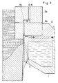
- FIG. 3 A further variant of the device according to the invention is shown in FIG. 3.
- the mold attachment is divided horizontally into two partial areas 22a, 22b.
- the gas line 16 also extends in the upper part 22a in the direction of the strand withdrawal and is only interrupted by a chamber 22c for gas distribution.
- the mold 1 has a support wall 12 for the secure positioning of the mold attachment 22a, b.
- the remaining parts, such as lubricant bore 4 and anteroom 15 correspond to the embodiment according to FIG. 2.
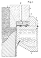
- a differently shaped gas guide block in the form of an insert 17 is provided between the mold 1 and the hot head 2.
- an insert 18 is arranged between the mold 1 and the hot head 2 in a corresponding manner.
- the gas line 19 is guided horizontally through the mold 1 and that and the insert part 18 into an antechamber 20, from which the gas reaches the annular gap 6.
- the mixture with the lubricant, which is supplied via bore 4 is variable between 2 and 10 mm before the outlet of the annular gap opening. All other features correspond to the parts described in connection with the previous figures.
Landscapes
- Engineering & Computer Science (AREA)
- Mechanical Engineering (AREA)
- Continuous Casting (AREA)
- Toys (AREA)
- Electrical Discharge Machining, Electrochemical Machining, And Combined Machining (AREA)
- Coating With Molten Metal (AREA)
- Treatment Of Steel In Its Molten State (AREA)
Abstract
Description
- Die Erfindung betrifft ein Verfahren zum Stranggießen in einer Stranggießkokille mit einem Kokillenaufsatz, dessen Innenwandung unter Bildung eines Überhanges über die Innenwandung der Stranggießkokille vorsteht, bei dem die Innenwandung der Stranggießkokille gekühlt und geschmiert wird, wobei ein unter Druck stehendes Gas wie Luft, Stickstoff oder Inertgas am Übergang des Kokillenaufsatzes in den Formhohlraum in die Stranggießkokille eingeleitet wird.
- Ein Verfahren und eine Vorrichtung der eingangs genannten Art ist aus der DE-OS 27 34 388 (Showa) bekannt. das bekannte Verfahren führt nur unter günstigen Voraussetzungen zu einigermaßen glatten Barrenoberflächen. Beim Angießen ist beispielsweise eine Überwachung und Regelung des Druckes von Gas und Schmieröl-Strömungsmenge erforderlich, sowie eine laufende Temperaturmessung zur Einstellung der Gießparameter. Dies führt im Betriebsfalle häufig zu Schwierigkeiten, die durch Schwankungen des Metallstandes und Änderungen des metallostatischen Druckes im laufenden Gießverfahren noch verstärkt werden.
- Ferner hat sich gezeigt, daß mit dem Verfahren nach DE-OS 27 34 388 bleihaltige Legierungen mit Gehalten bis zu 2,5 % Blei nicht zufriedenstellend zu vergießen sind. Diese Legierungen sind aber für die Herstellung von spanend zu bearbeitenden Stranggußprodukten von besonderer Bedeutung.
- Aufgabe der vorliegenden Erfindung ist es, die eingangs genannten Nachteile zu vermeiden und ein Verfahren und eine Vorrichtung zum Stranggießen zu entwickeln, womit unabhänig von den jeweilige- Gießbedingungen glatte und saubere Barrenoberflächen erzielt werden können. Die besondere Oberflächenqualität zeichnet sich durch Verhinderung von Klebstellen und Verringerung der Oberflächenseigerungen auf ein Maß aus, welches die Weiterverarbeitung ohne Abdrehen des Barrens ermöglicht.
- Erfindungsgemäß wird diese Aufgabe durch die in den Patentansprüchen angegebenen Merkmale gelöst. Es hat sich gezeigt, daß durch die Anordnung eines Ringspaltes in Richtung der Kokillenlauffläche und durch Vormischung von Trenn- und/oder Schmiermittel und Gas eine Nachregulierung der Gießparameter, insbesondere der Gas- und Schmiermittelmenge auch bei schwankendem Metallstand nicht erforderlich ist. Versuche mit gasförmigen Schmiermitteln wie Acetylen, Butadin, Propan und Trichloräthylen haben gezeigt, daß bei den in der Kokille herrschenden Bedingungen (Druck und Temperatur) eine einwandfreie Trennwirkung durch Zersetzung der gasförmigen Schmiermittel nicht möglich ist. Bei Zugabe von konventionellen Schmiermitteln ohne Gas parallel zur Kokillenachse treten in der Startphase Verbrennungen des Schmiermittels auf und anschließend Unterdosierung. Deshalb ist die Herstellung eines optimalen Schmiermittelzustandes nur durch Schmiermitteldosierung nicht möglich.
- Bei dem erfindungsgemäßen Verfahren hat es sich als wichtig herausgestellt, daß die Kokillenlauffläche unterhalb des Überhanges absolut glatt und frei von Bohrungen, Stufen oder Nuten ist. Insbesondere beim Angießen muß eine laminare Strömung parallel zur Kokillenlauffläche aufrechterhalten werden, damit das einfließende Metall nicht mit der Kokillenwand in Berührung kommt. Dieser Effekt wird dadurch verstärkt, daß zwischen Anfahrblock und Kokillenlauffläche ein Mindestabstand von 2-5 mm vorgesehen ist und in diesem Zwischenraum ein Unterdruck, vorzugsweise durch das am Kokillenaustrittsende ausgeblasene Kühlwasser (Wasserstrahl-Pumpen-Effekt) erzeugt wird.
- Im folgenden wird die Erfindung anhand eines Ausführungsbeispieles näher erläutert.
In Fig. 1 ist ein Querschnitt durch die erfindungsgemäße Kokille gezeigt. Man erkennt die Kokille 1 mit dem Kokillenaufsatzt der aus einem Heißkopf 2 und einem Gasführungsblock 3 mit Gaskanal 13 besteht. In der Kokille 1 ist eine Bohrung 4 für das Trenn- und/oder Schmiermittel und einen Kanal 5 für die Wasserkühlung enthalten. Zwischen Kokille 1, Heißkopf 2 und Gasführungsblock 3 wird ein Ringspalt 6 gebildet, der zumindest in der Nähe der Austrittsöffnung parallel und in Fortsetzung zur Lauffläche 7 verläuft. Wichtig ist hierbei, daß keinerlei Absätze, Bohrungen oder Nuten an der Lauffläche und im Austrittsbereich des Ringkanals vorhanden sind, damit eine annähernd laminare Strömung des Gemisches aus Trenn- und/oder Schmiermittel und Gas ermöglicht wird. - Im Betriebsfalle wird durch den Ringkanal 6 das Gas in den Raum unterhalb des Überhanges 8 dem Menikushohlraum 9 eingeblasen. Dabei reißt das Gas an der Schmiermittelzuführung (Bohrung 4) Teile des flüssigen Trenn- oder Schmiermittels mit, z. B. Öl. Es bilden sich Ga/Öl-Nebel (Emulsionen), die in laminare Strömung unterhalb des Überhanges 8 in Abzugsrichtung und parallel zur Kokillenlauffläche austreten und bis in den Zwischenraum von Kokille 1 und dem Anfahrblock reichen. Der dort wirksame Unterdruck, erzeugt durch den aus Kanal 5 austretenden Wasserstrahl, sorgt für Ausbildung eines ringförmigen Gas/Öl-Schleiers, der die Kokillenwand 7 vollständig gegenüber dem flüssigen Metall abschirmt.
- In zahlreichen Versuchen hat sich gezeigt, daß die erfindungsgemäße Zugabe eines Gas/Öl-Gemisches auch bei schwankendem Metallstand nicht durch Veränderung der Pumpendrücke oder Fördermengen geregelt werden muß. Offenbar ist die kombinierte Anwendung von Gas/Öl-Schleier und Saugwirkung entlang der Lauffläche so stark, daß auch bei Änderung des metallostatischen Druckes stets eine Pufferwirkung zwischen Metall und Lauffläche erhalten bleibt.
- Das erfindungsgemäße Verfahren wird vorzugsweise auf rißempfindliche Legierungsgruppen angewendet. Im folgenden wird ein Ausführungsbeispiel für Stränge mit 10 Zoll Durchmesser gegeben, wobei das Verhältnis von Trennmittel und Gas bei 3:1000 lag.
AlMg5 Gießgeschwindigkeit 70 mm pro Minute
AlCuMg2 Gießgeschwindigkeit 65 mm pro Minute
AlZnMgCu1,5 Gießgeschwindigkeit 65 mm pro Minute
AlCuMgPb Gießgeschwindigkeit 65 mm pro Minute - Diese Gießgeschwindigkeiten konnten unmittelbar nach dem Anfahren konstant gehalten werden. Weitere Gießparameter waren nicht nachzuregulieren. Die erhaltenen Barrenoberflächen zeigten eine hohe Oberflächenqualität.
- Weitere Ausführungsformen der Erfindung zeigen die Figuren 2 bis 5. Im Vergleich zu Fig. 1 ist der Kokillenaufsatz 22 in Fig. 2 einteilig ausgeführt. Die Bohrung für den Gaskanal 14 befindet sich im Kokillenaufsatz 22 und mündet in einen breiten Vorraum 15 zwischen Überhang 8 und Kokillenlauffläche 7. Hier findet die Gemischbildung mit dem Trenn- und/oder Schmiermittel statt, das aus Bohrung 4 in der Kokille 1 herangeführt wird. Zur Kühlung des Stranges 10 wird Wasser 11 aus dem Kanal 5 ausgeblasen.
- Eine weitere Variante der erfindungsgemäßen Vorrichtung zeigt Fig. 3. Hier ist der Kokillenaufsatz horizontal geteilt in zwei Teilflächen 22a,22b. Die Gasleitung 16 verläuft auch im oberen Teil 22a in Strangabzugsrichtung und wird nur durch eine Kammer 22c zur Gasverteilung unterbrochen. Die Kokille 1 weist eine Stützwand 12 zur sicheren Positionierung des Kokillenaufsatzes 22a,b auf. Die übrigen Teile, wie Schmiermittelbohrung 4 und Vorraum 15 entsprechen der Ausführung nach Fig. 2.
- In Fig. 4 ist zwischen der Kokille 1 und dem Heißkopf 2 ein anders geformter Gasführungsblock in Form eines Einsatzes 17 vorgesehen. In Fig. 5 ist in entsprechender Weise ein Einsatzteil 18 zwischen der Kokille 1 und dem Heißkopf 2 angeordnet. Im Unterschied zu Fig. 4 wird bei Fig. 5 die Gasleitung 19 horizontal durch die Kokille 1 und das und das Einsatzteil 18 in einen Vorraum 20 geführt, von dem aus das Gas in den Ringspalt 6 gelangt. Die Mischung mit dem Schmiermittel, das über Bohrung 4 zugeführt wird, erfolgt variabel zwischen 2 und 10 mm vor Austrittsöffnung der Ringspaltmündung. Alle übrigen Merkmale entsprechen den im Zusammenhang mit den vorhergehenden Figuren beschriebenen Teilen.
Claims (9)
Priority Applications (1)
| Application Number | Priority Date | Filing Date | Title |
|---|---|---|---|
| AT86111710T ATE47544T1 (de) | 1985-09-20 | 1986-08-23 | Verfahren und vorrichtung zum stranggiessen. |
Applications Claiming Priority (2)
| Application Number | Priority Date | Filing Date | Title |
|---|---|---|---|
| DE3533517 | 1985-09-20 | ||
| DE19853533517 DE3533517A1 (de) | 1985-09-20 | 1985-09-20 | Verfahren und vorrichtung zum stranggiessen |
Publications (2)
| Publication Number | Publication Date |
|---|---|
| EP0218855A1 true EP0218855A1 (de) | 1987-04-22 |
| EP0218855B1 EP0218855B1 (de) | 1989-10-25 |
Family
ID=6281441
Family Applications (1)
| Application Number | Title | Priority Date | Filing Date |
|---|---|---|---|
| EP86111710A Expired EP0218855B1 (de) | 1985-09-20 | 1986-08-23 | Verfahren und Vorrichtung zum Stranggiessen |
Country Status (7)
| Country | Link |
|---|---|
| EP (1) | EP0218855B1 (de) |
| JP (1) | JPH06104267B2 (de) |
| AT (1) | ATE47544T1 (de) |
| AU (1) | AU588369B2 (de) |
| CA (1) | CA1282220C (de) |
| DE (2) | DE3533517A1 (de) |
| NO (1) | NO167443C (de) |
Cited By (12)
| Publication number | Priority date | Publication date | Assignee | Title |
|---|---|---|---|---|
| EP0449771A1 (de) * | 1990-03-26 | 1991-10-02 | Alusuisse-Lonza Services Ag | Programmgesteuertes Einspeisen von schmelzflüssigem Metall in die Kokillen einer automatischen Stranggiessanlage |
| GB2222792B (en) * | 1988-09-14 | 1993-01-20 | Showa Denko Kk | Method for continuous casting a hollow metallic ingot and apparatus therefor |
| EP0566865A1 (de) * | 1992-04-15 | 1993-10-27 | VAW Aluminium AG | Gas- und Trennmittelzuführungs- und Verteilungssystem für eine Vorrichtung zum Stranggiessen |
| US5343933A (en) * | 1992-02-06 | 1994-09-06 | Vaw Aluminium Ag | Process and apparatus for continuously casting metals |
| FR2747063A1 (fr) * | 1996-04-05 | 1997-10-10 | Ugine Savoie Sa | Lingotiere de coulee continue en charge verticale des metaux |
| FR2747060A1 (fr) * | 1996-04-05 | 1997-10-10 | Ugine Savoie Sa | Procede de coulee continue des metaux et installation de coulee pour sa mise en oeuvre |
| FR2765126A1 (fr) * | 1997-06-26 | 1998-12-31 | Lorraine Laminage | Procede de coulee de metal liquide dans un conduit comprenant au moins deux pieces refractaires |
| FR2766394A1 (fr) * | 1997-07-23 | 1999-01-29 | Ascometal Sa | Reglage de la tete d'une lingotiere de coulee continue en charge des metaux |
| EP0941786A1 (de) * | 1998-03-13 | 1999-09-15 | Honda Giken Kogyo Kabushiki Kaisha | Verfahren und Vorrichtung zur Schmierung beim kontinuierlichen Giessen von Leichtmetallen |
| WO2002074471A1 (de) * | 2001-03-20 | 2002-09-26 | Sms Demag Aktiengesellschaft | Stranggiesskokille für flüssige metalle, insbesondere für flüssigen stahl |
| WO2005042185A1 (de) * | 2003-10-17 | 2005-05-12 | Loi Thermprocess Gmbh | Verfahren und eine vorrichtung zum stranggiessen von metall |
| CN109014090A (zh) * | 2018-08-31 | 2018-12-18 | 苏州铭恒金属科技有限公司 | 一种7系铝合金圆棒的热顶铸造工艺 |
Families Citing this family (3)
| Publication number | Priority date | Publication date | Assignee | Title |
|---|---|---|---|---|
| JPH0741389B2 (ja) * | 1987-10-02 | 1995-05-10 | 日本軽金属株式会社 | 鋳塊の半連続鋳造法及び鋳造装置 |
| US5052469A (en) * | 1988-09-20 | 1991-10-01 | Showa Denko Kabushiki Kaisha | Method for continuous casting of a hollow metallic ingot and apparatus therefor |
| KR102783704B1 (ko) * | 2020-09-02 | 2025-03-18 | 왁스타프, 인크. | 직접 냉각 주조 배기를 위한 시스템, 장치, 및 방법 |
Citations (4)
| Publication number | Priority date | Publication date | Assignee | Title |
|---|---|---|---|---|
| GB1143475A (en) * | 1965-07-24 | 1969-02-19 | Vaw Ver Aluminium Werke Ag | Method of continuously horizontally or vertically casting thin bands, plates or the like |
| DE1814658A1 (de) * | 1967-12-22 | 1969-07-17 | United States Steel Corp | Stranggiesskokille |
| US4157728A (en) * | 1976-07-29 | 1979-06-12 | Showa Denko Kabushiki Kaisha | Process for direct chill casting of metals |
| GB2129344A (en) * | 1982-10-20 | 1984-05-16 | Wagstaff Engineering Inc | Direct chill casting |
Family Cites Families (2)
| Publication number | Priority date | Publication date | Assignee | Title |
|---|---|---|---|---|
| JP6039456B2 (ja) | 2013-02-22 | 2016-12-07 | 大和ハウス工業株式会社 | 電力供給システム |
| JP6039458B2 (ja) | 2013-02-25 | 2016-12-07 | キヤノン株式会社 | 液体吐出ヘッド |
-
1985
- 1985-09-20 DE DE19853533517 patent/DE3533517A1/de not_active Withdrawn
-
1986
- 1986-07-31 NO NO863097A patent/NO167443C/no not_active IP Right Cessation
- 1986-08-23 DE DE8686111710T patent/DE3666549D1/de not_active Expired
- 1986-08-23 EP EP86111710A patent/EP0218855B1/de not_active Expired
- 1986-08-23 AT AT86111710T patent/ATE47544T1/de not_active IP Right Cessation
- 1986-09-19 JP JP61219889A patent/JPH06104267B2/ja not_active Expired - Lifetime
- 1986-09-19 AU AU62946/86A patent/AU588369B2/en not_active Expired
- 1986-09-19 CA CA000518615A patent/CA1282220C/en not_active Expired - Lifetime
Patent Citations (5)
| Publication number | Priority date | Publication date | Assignee | Title |
|---|---|---|---|---|
| GB1143475A (en) * | 1965-07-24 | 1969-02-19 | Vaw Ver Aluminium Werke Ag | Method of continuously horizontally or vertically casting thin bands, plates or the like |
| DE1814658A1 (de) * | 1967-12-22 | 1969-07-17 | United States Steel Corp | Stranggiesskokille |
| US4157728A (en) * | 1976-07-29 | 1979-06-12 | Showa Denko Kabushiki Kaisha | Process for direct chill casting of metals |
| US4157728B1 (de) * | 1976-07-29 | 1987-06-09 | ||
| GB2129344A (en) * | 1982-10-20 | 1984-05-16 | Wagstaff Engineering Inc | Direct chill casting |
Cited By (19)
| Publication number | Priority date | Publication date | Assignee | Title |
|---|---|---|---|---|
| GB2222792B (en) * | 1988-09-14 | 1993-01-20 | Showa Denko Kk | Method for continuous casting a hollow metallic ingot and apparatus therefor |
| EP0449771A1 (de) * | 1990-03-26 | 1991-10-02 | Alusuisse-Lonza Services Ag | Programmgesteuertes Einspeisen von schmelzflüssigem Metall in die Kokillen einer automatischen Stranggiessanlage |
| US5170838A (en) * | 1990-03-26 | 1992-12-15 | Alusuisse-Lonza Services Ltd. | Program-controlled feeding of molten metal into the dies of an automatic continuous casting plant |
| US5343933A (en) * | 1992-02-06 | 1994-09-06 | Vaw Aluminium Ag | Process and apparatus for continuously casting metals |
| EP0566865A1 (de) * | 1992-04-15 | 1993-10-27 | VAW Aluminium AG | Gas- und Trennmittelzuführungs- und Verteilungssystem für eine Vorrichtung zum Stranggiessen |
| US5320159A (en) * | 1992-04-15 | 1994-06-14 | Vaw Aluminum Ag | Continuous casting apparatus having gas and mold release agent supply and distribution plate |
| WO1997037795A1 (fr) * | 1996-04-05 | 1997-10-16 | Ugine Savoie | Procede et installation de coulee continue des metaux |
| FR2747060A1 (fr) * | 1996-04-05 | 1997-10-10 | Ugine Savoie Sa | Procede de coulee continue des metaux et installation de coulee pour sa mise en oeuvre |
| FR2747063A1 (fr) * | 1996-04-05 | 1997-10-10 | Ugine Savoie Sa | Lingotiere de coulee continue en charge verticale des metaux |
| WO1997037792A1 (fr) * | 1996-04-05 | 1997-10-16 | Ugine Savoie | Lingotiere de coulee continue en charge verticale des metaux |
| US6109335A (en) * | 1996-04-05 | 2000-08-29 | Ugine Savoie | Ingot mould for the continuous vertical casting of metals |
| FR2765126A1 (fr) * | 1997-06-26 | 1998-12-31 | Lorraine Laminage | Procede de coulee de metal liquide dans un conduit comprenant au moins deux pieces refractaires |
| FR2766394A1 (fr) * | 1997-07-23 | 1999-01-29 | Ascometal Sa | Reglage de la tete d'une lingotiere de coulee continue en charge des metaux |
| WO1999004918A1 (fr) * | 1997-07-23 | 1999-02-04 | Ascometal | Procede et dispositif pour la coulee continue en charge des metaux |
| EP0941786A1 (de) * | 1998-03-13 | 1999-09-15 | Honda Giken Kogyo Kabushiki Kaisha | Verfahren und Vorrichtung zur Schmierung beim kontinuierlichen Giessen von Leichtmetallen |
| US6840303B1 (en) | 1998-03-13 | 2005-01-11 | Honda Giken Kogyo Kabushiki Kaisha | Process for continuously casting light alloy and apparatus for continuously casting light alloy |
| WO2002074471A1 (de) * | 2001-03-20 | 2002-09-26 | Sms Demag Aktiengesellschaft | Stranggiesskokille für flüssige metalle, insbesondere für flüssigen stahl |
| WO2005042185A1 (de) * | 2003-10-17 | 2005-05-12 | Loi Thermprocess Gmbh | Verfahren und eine vorrichtung zum stranggiessen von metall |
| CN109014090A (zh) * | 2018-08-31 | 2018-12-18 | 苏州铭恒金属科技有限公司 | 一种7系铝合金圆棒的热顶铸造工艺 |
Also Published As
| Publication number | Publication date |
|---|---|
| NO863097L (no) | 1987-03-23 |
| CA1282220C (en) | 1991-04-02 |
| EP0218855B1 (de) | 1989-10-25 |
| AU6294686A (en) | 1987-03-26 |
| DE3533517A1 (de) | 1987-04-02 |
| JPH06104267B2 (ja) | 1994-12-21 |
| AU588369B2 (en) | 1989-09-14 |
| ATE47544T1 (de) | 1989-11-15 |
| NO167443C (no) | 1991-11-06 |
| NO167443B (no) | 1991-07-29 |
| DE3666549D1 (en) | 1989-11-30 |
| JPS6268657A (ja) | 1987-03-28 |
| NO863097D0 (no) | 1986-07-31 |
Similar Documents
| Publication | Publication Date | Title |
|---|---|---|
| EP0218855B1 (de) | Verfahren und Vorrichtung zum Stranggiessen | |
| DE2734388C2 (de) | Verfahren und Vorrichtung zum Stranggießen | |
| DE60011474T2 (de) | Giessen eines stahlbandes | |
| DE2252722A1 (de) | Verfahren und vorrichtung zum direkten kuehlen einer kontinuierlich gewalzten stange | |
| US5325910A (en) | Method and apparatus for continuous casting | |
| DE3113611C2 (de) | Verfahren zum Stranggießen von oberflächenfehlerfreien Stahlbrammen und -vorblöcken | |
| DE19637402C2 (de) | Bandgießen | |
| EP1181997A1 (de) | Verfahren und Vorrichtung zum kontinuierlichen Giessen von Stahlband aus Stahlschmelze | |
| EP0062606B1 (de) | Vorrichtung zum Kühlen eines Giessstranges während des Stranggiessens | |
| EP0566865B1 (de) | Gas- und Trennmittelzuführungs- und Verteilungssystem für eine Vorrichtung zum Stranggiessen | |
| DE2163928A1 (de) | Dreh-Stranggußverfahren für Metallrohlinge sowie Vorrichtung zur Durchführung dieses Verfahrens | |
| EP0746434A1 (de) | Verfahren und vorrichtung zum kühlen schmelzflüssigen stahls | |
| DE69913013T2 (de) | Vorrichtung zum Stranggiessen mit Badbewegung | |
| EP2483014B1 (de) | Verfahren zum bandgiessen von stahl und anlage zum bandgiessen | |
| DE68922285T2 (de) | Stranggiesskokille mit direkter Kühlung mit verstellbarem Kühlmitteltreffpunkt. | |
| DE830387C (de) | Verfahren und Vorrichtung zum stetigen Giessen eines Metallstranges | |
| DE69408603T2 (de) | Vakuumdruckgiessvorrichtung | |
| DE3210824A1 (de) | Verfahren und vorrichtung zur herstellung eines langen duennen aluminiumprodukts | |
| DE3856161T2 (de) | Verfahren und vorrichtung zum direkten giessen von metall zur bildung langer körper | |
| EP0107069A1 (de) | Verfahren zum Stranggiessen von Metallen, insbesondere von Stahl und Stranggiessanlagen dazu | |
| DE2518903A1 (de) | Stranggiessverfahren und -vorrichtung | |
| DE2418853A1 (de) | Verfahren und vorrichtung zum kontinuierlichen giessen und walzen eines products aus nichteisenmetall | |
| DE3406730C2 (de) | ||
| DE2419684A1 (de) | Verfahren und kokille zum vollkontinuierlichen giessen von metallischen straengen | |
| DE2613363A1 (de) | Stranggussmaschine |
Legal Events
| Date | Code | Title | Description |
|---|---|---|---|
| PUAI | Public reference made under article 153(3) epc to a published international application that has entered the european phase |
Free format text: ORIGINAL CODE: 0009012 |
|
| AK | Designated contracting states |
Kind code of ref document: A1 Designated state(s): AT BE CH DE FR GB IT LI LU NL SE |
|
| 17P | Request for examination filed |
Effective date: 19870609 |
|
| 17Q | First examination report despatched |
Effective date: 19880115 |
|
| GRAA | (expected) grant |
Free format text: ORIGINAL CODE: 0009210 |
|
| AK | Designated contracting states |
Kind code of ref document: B1 Designated state(s): AT BE CH DE FR GB IT LI LU NL SE |
|
| REF | Corresponds to: |
Ref document number: 47544 Country of ref document: AT Date of ref document: 19891115 Kind code of ref document: T |
|
| ITF | It: translation for a ep patent filed | ||
| REF | Corresponds to: |
Ref document number: 3666549 Country of ref document: DE Date of ref document: 19891130 |
|
| GBT | Gb: translation of ep patent filed (gb section 77(6)(a)/1977) | ||
| ET | Fr: translation filed | ||
| PLBE | No opposition filed within time limit |
Free format text: ORIGINAL CODE: 0009261 |
|
| STAA | Information on the status of an ep patent application or granted ep patent |
Free format text: STATUS: NO OPPOSITION FILED WITHIN TIME LIMIT |
|
| 26N | No opposition filed | ||
| ITTA | It: last paid annual fee | ||
| EPTA | Lu: last paid annual fee | ||
| EAL | Se: european patent in force in sweden |
Ref document number: 86111710.9 |
|
| PGFP | Annual fee paid to national office [announced via postgrant information from national office to epo] |
Ref country code: GB Payment date: 19960802 Year of fee payment: 11 |
|
| PGFP | Annual fee paid to national office [announced via postgrant information from national office to epo] |
Ref country code: BE Payment date: 19960822 Year of fee payment: 11 Ref country code: AT Payment date: 19960822 Year of fee payment: 11 |
|
| PGFP | Annual fee paid to national office [announced via postgrant information from national office to epo] |
Ref country code: LU Payment date: 19960901 Year of fee payment: 11 |
|
| PG25 | Lapsed in a contracting state [announced via postgrant information from national office to epo] |
Ref country code: LU Free format text: LAPSE BECAUSE OF NON-PAYMENT OF DUE FEES Effective date: 19970823 Ref country code: GB Free format text: LAPSE BECAUSE OF NON-PAYMENT OF DUE FEES Effective date: 19970823 Ref country code: AT Free format text: LAPSE BECAUSE OF NON-PAYMENT OF DUE FEES Effective date: 19970823 |
|
| PG25 | Lapsed in a contracting state [announced via postgrant information from national office to epo] |
Ref country code: BE Free format text: LAPSE BECAUSE OF NON-PAYMENT OF DUE FEES Effective date: 19970831 |
|
| BERE | Be: lapsed |
Owner name: VEREINIGTE ALUMINIUM-WERKE A.G. Effective date: 19970831 |
|
| GBPC | Gb: european patent ceased through non-payment of renewal fee |
Effective date: 19970823 |
|
| PGFP | Annual fee paid to national office [announced via postgrant information from national office to epo] |
Ref country code: SE Payment date: 20020823 Year of fee payment: 17 Ref country code: CH Payment date: 20020823 Year of fee payment: 17 |
|
| PG25 | Lapsed in a contracting state [announced via postgrant information from national office to epo] |
Ref country code: SE Free format text: LAPSE BECAUSE OF NON-PAYMENT OF DUE FEES Effective date: 20030824 |
|
| PG25 | Lapsed in a contracting state [announced via postgrant information from national office to epo] |
Ref country code: LI Free format text: LAPSE BECAUSE OF NON-PAYMENT OF DUE FEES Effective date: 20030831 Ref country code: CH Free format text: LAPSE BECAUSE OF NON-PAYMENT OF DUE FEES Effective date: 20030831 |
|
| EUG | Se: european patent has lapsed | ||
| REG | Reference to a national code |
Ref country code: CH Ref legal event code: PL |
|
| PGFP | Annual fee paid to national office [announced via postgrant information from national office to epo] |
Ref country code: NL Payment date: 20050812 Year of fee payment: 20 Ref country code: FR Payment date: 20050812 Year of fee payment: 20 Ref country code: DE Payment date: 20050812 Year of fee payment: 20 |
|
| PG25 | Lapsed in a contracting state [announced via postgrant information from national office to epo] |
Ref country code: IT Free format text: LAPSE BECAUSE OF NON-PAYMENT OF DUE FEES;WARNING: LAPSES OF ITALIAN PATENTS WITH EFFECTIVE DATE BEFORE 2007 MAY HAVE OCCURRED AT ANY TIME BEFORE 2007. THE CORRECT EFFECTIVE DATE MAY BE DIFFERENT FROM THE ONE RECORDED. Effective date: 20050823 |
|
| PG25 | Lapsed in a contracting state [announced via postgrant information from national office to epo] |
Ref country code: NL Free format text: LAPSE BECAUSE OF EXPIRATION OF PROTECTION Effective date: 20060823 |
|
| NLV7 | Nl: ceased due to reaching the maximum lifetime of a patent |
Effective date: 20060823 |
|
| REG | Reference to a national code |
Ref country code: FR Ref legal event code: TP Ref country code: FR Ref legal event code: CD Ref country code: FR Ref legal event code: CA |