EP0941786A1 - Verfahren und Vorrichtung zur Schmierung beim kontinuierlichen Giessen von Leichtmetallen - Google Patents
Verfahren und Vorrichtung zur Schmierung beim kontinuierlichen Giessen von Leichtmetallen Download PDFInfo
- Publication number
- EP0941786A1 EP0941786A1 EP99104936A EP99104936A EP0941786A1 EP 0941786 A1 EP0941786 A1 EP 0941786A1 EP 99104936 A EP99104936 A EP 99104936A EP 99104936 A EP99104936 A EP 99104936A EP 0941786 A1 EP0941786 A1 EP 0941786A1
- Authority
- EP
- European Patent Office
- Prior art keywords
- molten metal
- lubricating oil
- water
- casting mold
- spout
- Prior art date
- Legal status (The legal status is an assumption and is not a legal conclusion. Google has not performed a legal analysis and makes no representation as to the accuracy of the status listed.)
- Granted
Links
- 229910001234 light alloy Inorganic materials 0.000 title abstract description 14
- 238000000034 method Methods 0.000 title description 14
- 230000008569 process Effects 0.000 title description 14
- 230000001050 lubricating effect Effects 0.000 title description 3
- 238000005266 casting Methods 0.000 abstract description 129
- 229910052751 metal Inorganic materials 0.000 abstract description 127
- 239000002184 metal Substances 0.000 abstract description 127
- 239000010687 lubricating oil Substances 0.000 abstract description 122
- 238000009749 continuous casting Methods 0.000 abstract description 38
- 238000009834 vaporization Methods 0.000 abstract description 20
- 230000008016 vaporization Effects 0.000 abstract description 18
- 238000009825 accumulation Methods 0.000 abstract description 12
- 238000004519 manufacturing process Methods 0.000 abstract description 3
- 230000002093 peripheral effect Effects 0.000 description 41
- 239000003921 oil Substances 0.000 description 24
- 235000019198 oils Nutrition 0.000 description 24
- XEEYBQQBJWHFJM-UHFFFAOYSA-N Iron Chemical group [Fe] XEEYBQQBJWHFJM-UHFFFAOYSA-N 0.000 description 14
- 239000000498 cooling water Substances 0.000 description 12
- 238000013019 agitation Methods 0.000 description 11
- 229910000838 Al alloy Inorganic materials 0.000 description 10
- 239000000314 lubricant Substances 0.000 description 10
- 239000011247 coating layer Substances 0.000 description 9
- 239000000203 mixture Substances 0.000 description 9
- 239000007787 solid Substances 0.000 description 8
- 238000007788 roughening Methods 0.000 description 6
- 239000004810 polytetrafluoroethylene Substances 0.000 description 5
- 229920001343 polytetrafluoroethylene Polymers 0.000 description 5
- 239000010935 stainless steel Substances 0.000 description 5
- 229910001220 stainless steel Inorganic materials 0.000 description 5
- VYPSYNLAJGMNEJ-UHFFFAOYSA-N Silicium dioxide Chemical compound O=[Si]=O VYPSYNLAJGMNEJ-UHFFFAOYSA-N 0.000 description 4
- 238000004891 communication Methods 0.000 description 4
- 239000011888 foil Substances 0.000 description 4
- 239000000463 material Substances 0.000 description 4
- XLYOFNOQVPJJNP-UHFFFAOYSA-N water Substances O XLYOFNOQVPJJNP-UHFFFAOYSA-N 0.000 description 4
- 229910000906 Bronze Inorganic materials 0.000 description 3
- OAICVXFJPJFONN-UHFFFAOYSA-N Phosphorus Chemical compound [P] OAICVXFJPJFONN-UHFFFAOYSA-N 0.000 description 3
- 239000010974 bronze Substances 0.000 description 3
- 238000010276 construction Methods 0.000 description 3
- KUNSUQLRTQLHQQ-UHFFFAOYSA-N copper tin Chemical compound [Cu].[Sn] KUNSUQLRTQLHQQ-UHFFFAOYSA-N 0.000 description 3
- 238000005461 lubrication Methods 0.000 description 3
- 239000000843 powder Substances 0.000 description 3
- 239000010723 turbine oil Substances 0.000 description 3
- PNEYBMLMFCGWSK-UHFFFAOYSA-N aluminium oxide Inorganic materials [O-2].[O-2].[O-2].[Al+3].[Al+3] PNEYBMLMFCGWSK-UHFFFAOYSA-N 0.000 description 2
- 239000000378 calcium silicate Substances 0.000 description 2
- 229910052918 calcium silicate Inorganic materials 0.000 description 2
- OYACROKNLOSFPA-UHFFFAOYSA-N calcium;dioxido(oxo)silane Chemical compound [Ca+2].[O-][Si]([O-])=O OYACROKNLOSFPA-UHFFFAOYSA-N 0.000 description 2
- 239000010949 copper Substances 0.000 description 2
- 238000010586 diagram Methods 0.000 description 2
- 238000007599 discharging Methods 0.000 description 2
- 238000010438 heat treatment Methods 0.000 description 2
- 238000002844 melting Methods 0.000 description 2
- 230000008018 melting Effects 0.000 description 2
- 239000000377 silicon dioxide Substances 0.000 description 2
- 239000007858 starting material Substances 0.000 description 2
- OKTJSMMVPCPJKN-UHFFFAOYSA-N Carbon Chemical compound [C] OKTJSMMVPCPJKN-UHFFFAOYSA-N 0.000 description 1
- RYGMFSIKBFXOCR-UHFFFAOYSA-N Copper Chemical compound [Cu] RYGMFSIKBFXOCR-UHFFFAOYSA-N 0.000 description 1
- 229910000861 Mg alloy Inorganic materials 0.000 description 1
- ZOKXTWBITQBERF-UHFFFAOYSA-N Molybdenum Chemical compound [Mo] ZOKXTWBITQBERF-UHFFFAOYSA-N 0.000 description 1
- 239000000470 constituent Substances 0.000 description 1
- 229910052802 copper Inorganic materials 0.000 description 1
- 230000007547 defect Effects 0.000 description 1
- 239000002480 mineral oil Substances 0.000 description 1
- 235000010446 mineral oil Nutrition 0.000 description 1
- CWQXQMHSOZUFJS-UHFFFAOYSA-N molybdenum disulfide Chemical compound S=[Mo]=S CWQXQMHSOZUFJS-UHFFFAOYSA-N 0.000 description 1
- 229910052982 molybdenum disulfide Inorganic materials 0.000 description 1
- 230000001737 promoting effect Effects 0.000 description 1
- 239000010499 rapseed oil Substances 0.000 description 1
- 230000009467 reduction Effects 0.000 description 1
- 230000001105 regulatory effect Effects 0.000 description 1
- 230000004044 response Effects 0.000 description 1
- 239000000126 substance Substances 0.000 description 1
- 238000010117 thixocasting Methods 0.000 description 1
- 235000015112 vegetable and seed oil Nutrition 0.000 description 1
- 239000008158 vegetable oil Substances 0.000 description 1
Images


Classifications
-
- B—PERFORMING OPERATIONS; TRANSPORTING
- B22—CASTING; POWDER METALLURGY
- B22D—CASTING OF METALS; CASTING OF OTHER SUBSTANCES BY THE SAME PROCESSES OR DEVICES
- B22D11/00—Continuous casting of metals, i.e. casting in indefinite lengths
- B22D11/07—Lubricating the moulds
-
- B—PERFORMING OPERATIONS; TRANSPORTING
- B22—CASTING; POWDER METALLURGY
- B22D—CASTING OF METALS; CASTING OF OTHER SUBSTANCES BY THE SAME PROCESSES OR DEVICES
- B22D11/00—Continuous casting of metals, i.e. casting in indefinite lengths
- B22D11/04—Continuous casting of metals, i.e. casting in indefinite lengths into open-ended moulds
- B22D11/0401—Moulds provided with a feed head
-
- B—PERFORMING OPERATIONS; TRANSPORTING
- B22—CASTING; POWDER METALLURGY
- B22D—CASTING OF METALS; CASTING OF OTHER SUBSTANCES BY THE SAME PROCESSES OR DEVICES
- B22D11/00—Continuous casting of metals, i.e. casting in indefinite lengths
- B22D11/10—Supplying or treating molten metal
- B22D11/11—Treating the molten metal
- B22D11/114—Treating the molten metal by using agitating or vibrating means
- B22D11/115—Treating the molten metal by using agitating or vibrating means by using magnetic fields
Definitions
- the present invention relates to a process for continuously casting a light alloy and to an apparatus for continuously casting a light alloy.
- a process for producing a light alloy ingot using a continuous casting apparatus which will be described below, is conventionally known as a process for continuously casting a light alloy (an aluminum alloy, a magnesium alloy or the like).
- the apparatus includes a cylindrical water-cooled casting mold which is disposed immediately below a spout having an upward-turned molten metal receiving port and a downward-turned molten metal outlet and which has an inside radius larger than that of the molten metal outlet, and a lubricating oil discharge passage provided below the spout to supply a lubricating oil to a portion between the water-cooled casting mold and the molten metal brought into contact with the water-cooled casting mold.
- a plurality of lubricating oil discharge passages are generally disposed in a circumferential direction of the water-cooled casting mold.
- the dynamic viscosity of the lubricating oil is varied remarkably depending on the temperature and cannot be constant in each of the discharge passages. For this reason, a difference between discharge resistances to the lubricating oil in the discharge passages is produced and as a result, the amount of lubricating oil fed out of each of the discharge passages is liable to be non-uniform. This also causes the casting skin failure.
- each of the discharge ports has a predetermined length in a direction of discharging of a lubricating oil, and the amount of lubricating oil discharged is controlled by constricting each of the discharge ports.
- the lubricating oil is not uniformly discharged from each of the discharge ports, whereby the roughening of a casting skin of a produced ingot is produced.
- a continuous casting process for continuously casting a light alloy for producing an ingot made of a light alloy by using a continuous casting apparatus comprising a cylindrical water-cooled casting mold which is disposed immediately below a spout having an upward-turned molten metal receiving port and a downward-turned molten metal outlet and which has an inside radius larger than an inside radius of the molten metal outlet, and lubricating oil discharge passages provided below the spout to supply a lubricating oil to a portion between the water-cooled casting mold and the molten metal brought into contact with the water-cooled casting mold, wherein the lubricating oil is an oil having a vaporization rate of 30 % or more at 300°C, and an annular gas accumulation for spacing the molten metal apart from outlets of the lubricating oil discharge passages is defined below an annular protrusion of the spout.
- the entering of the molten metal into the outlet can be inhibited by the annular gas accumulation and hence, the generation of a casting skin failure due to the outlet can be avoided.
- the lubricating oil which has not been vaporized lubricates the portion between the water-cooled casting mold and the molten metal.
- the vaporization rate of the lubricating oil at 300°C may be 100 %.
- the gas in a lower end of the gas accumulation is cooled and liquefied by the water-cooled casting mold, and the liquefied lubricating oil contributes to the lubrication between the water-cooled casting mold and the molten metal.
- the vaporisation rate of the lubricating oil at 300°C is lower than 30 %, it is impossible to form a gas accumulation having a pressure enough to space the molten metal apart from the outlet.
- the gas accumulation exhibits the function to inhibit the entering of the molten metal into the outlet even in the continuous casting process in which a circumferential electromagnetic agitating force is applied to the molten metal.
- the amount A of solid lubricating agent mixed is set in a range of 1 % by weight ⁇ A ⁇ 10 % by weight. If the amount A is lower than 1 % by weight, the use of the solid lubricating agent is meaningless. On the other hand, if A > 10 % by weight, the amount of the solid lubricating agent is excessive, thereby causing an oil-baking on an outer peripheral surface of an ingot.
- the dynamic viscosity ⁇ of the lubricating oil in an inlet of each of the lubricating oil discharge passages may be set in a range of ⁇ ⁇ 30 mm 2 /sec. If the dynamic viscosity ⁇ is set in such range, the variation in viscosity attendant on a variation in temperature of the lubricating oil can be reduced extremely to uniformize the amount of lubricating oil distributed from each of the discharge passages. However, if the dynamic viscosity ⁇ is higher than 30 mm 2 /sec., a casting skin failure of an ingot is liable to be produced.
- a continuous casting apparatus for continuously casting a light alloy comprising a spout having an upward-turned molten metal receiving port and a downward-turned molten metal outlet, a cylindrical water-cooled casting mold which is disposed immediately below the spout to cool a molten metal from the molten metal outlet and which has an inside radius r 1 larger than an inside radius r 2 of the molten metal outlet, an agitator for applying a circumferential electromagnetic agitating force to the molten metal, lubricating oil discharge passages provided between an annular lower end face of the spout and an annular upper end face of the water-cooled casting mold to supply a lubricating oil to a portion between the water-cooled casting mold and the molten metal brought into contact with the water-cooled casting mold, and a coating layer which is provided on the annular upper end face and which has a heat conductivity coefficient lower than that of the water-cooled casting mold
- the dropping of the temperature of the lubricating oil by the water-cooled casting mold can be inhibited in accordance with the coating layer, thereby promoting the vaporization of the lubricating oil to achieve the intended object.
- the lubricating oil discharge passages can be defined by a discharge passage defining plate.
- the discharge passage defining plate is formed from a material having a heat conductivity coefficient lower than that of the water-cooled casting mold to promote the vaporization rate of the lubricating oil.
- the apparatus includes a lubricating oil supply passageway which includes the discharge passages, that portion of the lubricating oil supply passageway which is connected to the discharge passages being disposed around the spout.
- the apparatus may includes a lubricating oil heating heater disposed in the vicinity of inlets of the discharge passages.
- a lubricating oil heating heater disposed in the vicinity of inlets of the discharge passages.
- a continuous casting apparatus comprising a cylindrical water-cooled casting mold having a vertically-turned axis, and a supply passageway for supplying a lubricating oil to an inner peripheral surface side of the cylindrical water-cooled casting mold, the supply passageway including a plurality of discharge ports disposed in the vicinity of an annular upper end of the cylindrical water-cooled casting mold, and a plurality of distributing passages for distributing the lubricating oil to the discharge ports and having constrictions, the length L of each of the discharge ports in an ingot-withdrawing direction being set at a value enough to avoid the generation of a break-out, the relationship between a sum A 1 of sectional areas of all the discharge ports and a sum A 2 of sectional areas of all the constrictions being determined to ensure A 1 > A 2 , the ratio A 2 /A 1 of both the sums A 1 and A 2 of the sectional areas being in a range Lmin/L ⁇
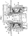
- a first embodiment of a hot-top type continuous casting apparatus 1 shown in Figs.1 and 2 includes a drum-shaped body 2 having an axis turned vertically.
- the drum-shaped body 2 is comprised of an inner peripheral wall 3, an outer peripheral wall 4 disposed at a predetermined distance around the outer periphery of the inner peripheral wall 3, an annular upper end wall 5 located at upper ends of both the walls 3 and 4, and an annular lower end wall 6 located at lower ends of both the walls 3 and 4.
- the inner peripheral wall 3 comprises an upper cylindrical portion 7 and a lower cylindrical portion 8.
- An inward-turned annular portion 10 of an annular rubber seal 9 fitted over an outer peripheral surface of a lower portion of the upper cylindrical portion 7 is interposed between both the cylindrical portions 7 and 8 to seal a section between both the cylindrical portions 7 and 8.
- a lower half of the upper cylindrical portion 7 is formed at a thickness larger than that of an upper half, so that an annular step is formed inside the lower half, thereby forming a cylindrical water-cooled casting mold 13. Therefore, the cylindrical water-cooled casting mold 13 has a cylindrical portion 12 comprised of the upper half, and an annular upper end face 11 comprised of the annular step.
- the cylindrical water-cooled casting mold 13 is formed of an aluminum alloy (e.g., A5052).
- the cylindrical portion 12 surrounds a spout 15 with a thin cylindrical member 14 interposed therebetween, and an annular lower end face 17 defining a downward-turned molten metal outlet 16 of the spout 15 abuts against the annular upper end face 11 of the water-cooled casting mold 13.
- An annular removal-preventing plate 18 is fitted over a portion of the spout 15, which protrudes from the upper end wall 5. The removal-preventing plate 18 is fixed to the upper end wall 5.
- the spout 15 is formed of calcium silicate having a heat-insulating property and a fire resistance. Alternatively, alumina, silica or the like may be used as a material for forming the spout 15.
- the water-cooled casting mold 13 has an inside radius r 1 set larger than an inside radius r 2 at the molten metal outlet 16 of the spout 15. Therefore, a portion around the molten metal outlet 16 of the spout 15 presents an annular protrusion 15a.
- a molten metal tub 19 for horizontal pouring of a molten metal is disposed above the spout 15 and has a downward-turned molten metal supply port 20 which communicates with an upward-turned molten metal receiving port 21 of the spout 15.
- An electromagnetic induction-type agitator 23 is disposed in a cylindrical closed space 22 between the inner and outer peripheral walls 3 and 4 of the drum-shaped body 2 and applies a circumferential electromagnetic agitating force to the molten metal m within the spout 15.
- the agitator 23 comprises a cylindrical stratified iron core 24 and a plurality of coils 25 wound around the stratified iron core 24.
- the stratified iron core 24 is comprised of a cylindrical portion 26, and a plurality of projections 27 disposed at circumferentially equal distances around an inner peripheral surface of the cylindrical portion 26 and extending along a generatrix line, as best shown in Fig.3.
- Each of the coils 25 is wound around the adjacent projections 27, so that portions of two coils 25 are overlapped on each other at one projection 27.
- a thin cylindrical coil-retaining member 28 is fitted inside the stratified iron core 24, so that tip end faces of the projections 27 are in close contact with the coil-retaining member 28.
- the cylindrical member 28 is fixed within the cylindrical closed space 22 with a portion of its inner peripheral surface in close contact with the annular rubber seal 9.
- the stratified iron core 24 is placed onto an annular support member 29 and fixed to the support member 29 by a plurality of bolts 30 and nuts 31.
- a plurality of connectors 32 are prepared two for one coil 25 and mounted through the lower end wall 6 by a water-tight means.
- a plurality of water supply ports 33 are defined in the outer peripheral wall 4, so that cooling water w is supplied through each of the water supply ports 33 into the closed space 22.
- a plurality of through-bores 34 are defined in the cylindrical member 28 inside the stratified iron core 24 and located in the vicinity of an upper end of the cylindrical member 28 and thus, a cooling water sump 35 is provided above the annular rubber seal 9.
- the water-cooled casting mold 13 is cooled by means of the cooling water sump 35, and has a plurality of ejection bores 36 for ejecting the cooling water w in the cooling water sump 35 obliquely and downwards.
- a lubricating oil supply passageway F L which will be described below is provided around the spout 15.
- a lower plate 37 of the upper end wall 5 is integrally provided at an upper end of the upper cylindrical portion 7 of the inner peripheral wall 3.
- An annular passage 39 surrounding the spout 15, and a plurality of straight passages 40 extending radiately from the annular passage 39.
- An introducing passage 41 defined in the upper plate 38 communicates with ends of the straight passages 40, and is connected to an oil supply pump P.
- a cylindrical passage 42 is defined around the spout 15, e.g., between an outer peripheral surface of the cylindrical member 14 and an inner peripheral surface of the cylindrical portion 12 in the illustrated embodiment, and a plurality of obliquely-turned through-bores 43 are defined in a connection between the cylindrical portion 12 and the lower plate 37 to permit the communication between the cylindrical passage 42 and the annular passage 39.
- a lower end of the cylindrical passage 42 communicates with a plurality of discharge passages 44 defined at circumferentially equal distances in the water-cooled casting mold 13.
- Each of the discharge passages 44 is of an L-shape, and has an inlet 44a which is located at a tip end of a vertical portion of each discharge passage 44 and which opens into the annular upper end face 11 to communicate with the cylindrical passage 42, and an outlet 44b which is located at a tip end of a horizontal portion of each discharge passage 44 and which opens into an inner peripheral surface.
- the lubricating oil supply passageway F L is comprised of the introducing passage 41, the straight passages 40, the annular passage 39, the through-bores 43, the cylindrical passage (the portion connected to the discharge passages 44) 42 and the discharge passages 44.
- An oil having a vaporization rate of 30 % or more at 300°C e.g., Terasu oil #46, #32 or #22 (which is a trade name and is commercially available from Showa Shell Co.) is commonly used alone as the lubricating oil Lu.
- Another lubrication oil may be mixed with this oil.
- a solid lubricating agent which is mixed into the lubricating oil Lu to form a lubricating agent mixture which may be used, is a PTFE powder, a graphite powder, a BN powder, a molybdenum powder (e.g., a molybdenum disulfide) or the like.
- the amount A of solid lubricating agent mixed is set in a range of 1 % by weight ⁇ A ⁇ 10 % by weight.
- the lubricating oil Lu while is flowing in the cylindrical passage 42, is heated by the spout 15, e.g., the cylindrical member 14 which has received a heat transferred from the spout 15 in the illustrated embodiment, so that the dynamic viscosity is stabilized, whereby the amount of lubricating oil delivered from each of the discharge passages 44 is equalized.
- the temperature of the molten metal m existing in the vicinity of the outlet 44b of each of the lubricating oil discharge passages 44 is in a range of 300 to 400°C and hence, the lubricating oil Lu existing in the outlet 44b and in the vicinity of the outlet 44b is further heated by the molten metal m , whereby 30 % or more of the lubricating oil Lu is vaporized.
- an annular gas accumulation G for spacing the molten metal m from each of the outlets 44b is formed below the annular protrusion 15a of the spout 15.
- the entering of the molten metal m into each of the outlets 44b can be inhibited by the annular gas accumulation G and hence, the generation of a casting skin failure in an outer peripheral surface of the ingot I due to the outlets 44b can be avoided.
- the unvaporized lubricating oil Lu and/or the solid lubricating agent lubricate an area between the water-cooled casting mold 13 and the molten metal m .
- the annular gas accumulation G is formed even when an electromagnetic agitation as described above is provided. Therefore, the annular gas accumulation G is, of course, formed even in a usual continuous casting process in which the electromagnetic agitation is not provided.
- the spheroidization of the crystallized products having a high melting point is conducted by the electromagnetic agitation and hence, an ingot I optimal for a thixocasting process can be obtained.
- a second embodiment of a continuous casting apparatus shown in Figs.4 and 5 is different from the first embodiment in respect of only the structure of lubricating oil discharge passages 44.
- a plurality of straight discharge passages 44 are provided between the annular lower end face 17 of the spout 15 and the annular upper end face 11 of the water-cooled casting mold 13.
- a plurality of V-grooves 45 are defined radiately in the annular upper end face 11 of the water-cooled casting mold 13, and the discharge passages 44 are defined by closing upward-turned openings of the V-grooves 45 by the annular lower end face 17 of the spout 15 and the lower end face of the cylindrical member 14.
- a coating layer 46 having a heat-conductivity coefficient lower than that [0.331 cal/(cm ⁇ s ⁇ deg)] of the water-cooled casting mold 13 made of the aluminum alloy (A5052) is provided on the annular upper end face 11.
- the coating layer 46 is formed of a stainless steel foil [0.0617 cal/(cm ⁇ s ⁇ deg)] having a thickness of 50 ⁇ m, and the stainless steel foil is stuck on an inner surface of each of the V-grooves 45 and an upper surface of each of lands 47.
- a third embodiment of a continuous casting apparatus shown in Figs.6 to 10 is likewise different from the first embodiment in respect of only the structure of lubricating oil discharge passages 44.
- a discharge passage defining plate 48 defining a plurality of discharge passages 44 is disposed between the annular lower end face 17 of the spout 15 and the annular upper end face 11 of the water-cooled casting mold 13.
- the discharge passage defining plate 48 is formed of a material having a heat conductivity coefficient lower than the heat conductivity coefficient [0.331 cal/(cm ⁇ s ⁇ deg)] of the water-cooled casting mold 13, e.g., phosphor bronze [0.202 cal/(cm ⁇ s ⁇ deg)], a stainless steel [0.0617 cal/(cm ⁇ s ⁇ deg)] or the like.
- the discharge passage defining plate 48 is comprised of thin upper and lower annular plates 49 and 50 disposed in a superposed manner between the spout 15 and the water-cooled casting mold 13.
- the lower annular plate 50 has a plurality of discharge passage slits which are disposed radiately, so that they extend from its inner peripheral surface to its outer periphery, and openings in the inner peripheral surface are outlets 44b.
- An end of each of the slits 51 on the side of its outer periphery is formed into a circular bore 52.
- the upper annular plate 49 has a plurality of U-shaped notch inlets 44a disposed radiately in its outer periphery.
- Each of the inlets 44a is matched with each of the circular bores 52 located in the outer periphery of the lower annular plate 50, and is connected to the annular passage 42 located on the lubricating oil supply side, as best shown in Figs.6 and 7.
- Each of the inlets 44a has an area sufficiently larger than each of the circular bores 52.
- the upper annular plate 49 is disposed on the side of the annular lower end face 17 of the spout 15, as described above, the narrowing of the discharge passage 44 due to the thermal deformation of the spout 15 can be avoided.
- the circular bore 52 is provided in each of the slits 51 and the area of each of the inlets 44a is larger, the lubricating oil Lu from the cylindrical passage 42 can be introduced smoothly through the inlets 44a and the circular bores 52 to main slit portions 54.
- the lower annular plate 50 functions as the discharge passage defining plate 48 by only itself.
- examples 1 to 11 of ingots having a diameter of 152 mm were produced in a casting manner with varied types of lubricating oils (including a lubricating mixture) Lu under conditions of a casting speed of 170 mm/min; an amount of lubricating oil supplied of 1 cc/min; an amount of cooling water supplied of 80 liters/min and a temperature of a molten metal set in a range of 650 to 690°C in the molten metal receiving port 21 of the spout 15 and under an electromagnetic agitation of 50 Hz and 30 A using a four-pole coil.
- lubricating oils including a lubricating mixture
- Table 1 shows the type of the lubricating oil Lu used in the casting production of the examples 1 to 11, the vaporization rate of the lubricating oil at 300°C and 400°C, the amount A of PTFE powder mixed and the state of the casting skin of the ingot I.
- Passable means that the casting skin of the ingot I is smooth
- Good means that the degree of smoothness is better than that in a case of "Passable”.
- Terasu oil #22 which is commercially available from Showa Shell Co.
- caster oil 9 : 1 (by weight ratio).
- Example 6 Mixture of Terasu oil #22 and caster oil 49 98 - Passable Example 7 92 4.2 Good
- Example 8 Turbine oil (FBK#100 commercially available from Nisseki Co.) 12 64 - Failure (torn off)
- Example 10 Turbine oil (FBK#32 commercially available from Nisseki Co.) 19 100
- examples 1 to 3 of ingots I having a diameter of 152 mm were produced in a casting manner using JIS AC2B as an aluminum alloy which was a starting material under conditions of a casting speed of 170 mm/min; a lubricating oil comprising Terasu oil #46 commercially available from Showa Shell Co.; an amount of lubricating oil supplied of 1 cc/min; an amount of cooling water supplied of 80 liter/min; a temperature of a molten metal set in a range of 650 to 690°C in the molten metal receiving port 21 of the spout 15 and under an electromagnetic agitation of 50 Hz and 30
- Table 2 shows the feature of the lubricating oil discharge passage 44 and the state of the casting skin of the ingot for the examples 1 to 3.
- “Excellent” means that the degree of the smoothness of the casting skin in the ingot I is better than that in "Good”.
- Ingot Feature of lubricating oil discharge passage State of casting skin of ingot Example 1 Stainless coating layer (Figs. 4 and 5) Excellent Example 2 Upper and lower annular plates (Figs.6 to 10) Excellent Example 3 Upper annular plate (Figs.8 and 9) Good
- a coating layer 46 formed of a copper (Cu) foil in place of a stainless steel foil namely, a coating layer 46 having a heat conductivity coefficient [0.923 cal/(cm ⁇ s ⁇ deg)] higher than the heat conductivity coefficient [0.331 cal/(cm ⁇ s ⁇ deg)] of the water-cooled casting mold 13 was used in the second embodiment of the continuous casting apparatus shown in Figs.4 and 5, the state of the casting surface of the ingot I was "Passable". From this, the those skilled in the art will understand the meaning that the heat conductivity coefficient of the coating layer 46 is set lower than that of the water-cooled casting mold 13.
- a fifth embodiment of a continuous casting apparatus 1 will now be described, in which the generation of the failure of a casting skin in a light alloy ingot I due to the outlet 44b can be avoided without provision of a gas accumulation as described above.
- the fifth embodiment of the continuous casting apparatus 1 has a structure substantially similar to that shown in Figs.6 to 10, and includes a spout 15 having an upward-turned molten metal receiving port 21 and a downward-turned molten metal outlet 16, a cylindrical water-cooled casting mold 13 disposed immediately below the spout 15 to cool a molten metal m from the molten metal outlet 16, an agitator 23 for applying a circumferential electromagnetic agitating force to the molten metal m , and thin upper and lower annular plates 49 and 50 which are disposed in a superposed manner between an annular lower end face 17 of the spout 15 and an annular upper end face 11 of the water-cooled casting mold 13 to define a lubricating oil discharge passage 44 having an outlet 44b having a size enough to supply a lubricating oil Lu to between the water-cooled casting mold 13 and the molten metal m contacting with the water-cooled casting mold 13 and to inhibit the entering of the molten metal m .
- the lower annular plate 50 has a plurality of outlet slits 51 extending from its inner peripheral surface to its outer peripheral surface and having openings in the inner peripheral surface, which are the outlets 44b.
- the upper annular plate 49 has a plurality of U-shaped notch inlets 44a each of which is matched with an end of each of the slits 51 located in the outer periphery of the lower annular plate 50, i.e., a circular bore 52 and connected to a cylindrical passage 42 located on the lubricating oil supply side.
- the upper and lower annular plates 49 and 50 are formed of a stainless steel (JIS SUS304H) and have a thickness T (Fig.6) set at 50 ⁇ m.
- Each of the slits 51 has a width Wd (Fig.9) set at 0.5 mm, and the circular bore 52 has a diameter D (Fig.9) set at 1.0 mm. Therefore, the size of the opening of the outlet 44b is 50 ⁇ m long and 0.5 mm wide. If the longitudinal length of the opening is 100 ⁇ m or less under the conditions of electromagnetic agitation, it is possible to inhibit the entering of the molten metal m into the outlet 44b.
- a sixth embodiment of a continuous casting apparatus 1 shown in Fig.11 is similar to the apparatus of the third embodiment, except that a lubricating oil heating heater 55 is disposed in the vicinity of the inlet 44a of the discharge passage 44.
- a lubricating oil heating heater 55 is disposed in the vicinity of the inlet 44a of the discharge passage 44.
- an annular groove 56 is provided immediately above the discharge passage defining plate 48 at the lower portion of the inner peripheral surface of the cylindrical member 12 to face the cylindrical passage 42, and the annular electric heater 55 is disposed in the annular groove 56.
- the lubricating oil Lu can be positively heated by the heater 55, so that the dynamic viscosity thereof can be stabilized, whereby the lubricating oil Lu can be delivered substantially uniformly from the discharge passages 44.
- that portion of the lubricating oil supply passageway F L which is connected to the discharge passages 44 may not be disposed around the spout 15.
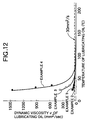
- Table 3 shows the type of examples 1 to 4 of the lubricating oil Lu and the amount A of PTFE mixed.
- the examples 1 to 4 correspond to the examples 1, and 5 to 7 of the ingots in Table 1, respectively and hence, the vaporization rate thereof at 300°C is 30 % or more.
- Lubricating oil Type Amount A (% by weight) of PTFE mixed Example 1 Terasu oil #46 commercially available from Showa Shell Co. - Example 2 Terasu oil #32 commercially available from Showa Shell Co. - Example 3 Mixture of Terasu oil #22 commercially available from Showa Shell Co. and caster oil - Example 4 4.2
- Fig.12 shows the relationship between the temperature and the dynamic viscosity ⁇ of the lubricating oil Lu for the examples 1 to 4. It can be seen from Fig.12 that in a range of the dynamic viscosity ⁇ ⁇ 30 mm 2 /sec., a variation in the dynamic viscosity ⁇ relative to a variation in temperature is extremely small.
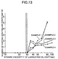
- the casting conditions were applied to those in Example 1, except that the temperature of the molten metal was set at 730°C, and the heater 55 was regulated to vary the temperature of the lubricating oil Lu in the inlet 44a of each of the discharge passages 44 to various levels.
- the above-described "number of casting skin failure points" was determined as an average number of casting skin failure points located in an area of 1 m in the outer peripheral surface of the ingot.
- Fig.13 shows the results of the above consideration. As apparent from Fig.13, if the dynamic viscosity ⁇ of the examples 1 to 4 of the lubricating oil is set in a range of ⁇ ⁇ 30 mm 2 /sec., an ingot I having a good casting skin can be produced.
- a heater 55 can be also utilized in the first, second, fourth and fifth embodiments of the continuous casting apparatus 1.
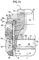
- a hot-top type continuous casting apparatus 1 shown in Figs.14 and 15 has a structure similar to that described in EMBODIMENT I. More specifically, the hot-top type continuous casting apparatus 1 has a drum-shaped body 2 having an axis turned vertically.
- the drum-shaped body 2 is comprised of an inner peripheral wall 3, an outer peripheral wall 4 disposed at a predetermined distance around an outer periphery of the inner peripheral wall 3, an annular upper end wall 5 located at upper ends of the walls 3 and 4, and an annular lower end wall 6 located at lower ends of the walls 3 and 4.
- the inner peripheral wall 3 comprises an upper cylindrical portion 7 and a lower cylindrical portion 8.
- An inward-turned annular portion 10 of an annular rubber seal 9 fitted over an outer peripheral surface of a lower portion of the upper cylindrical portion 7 is interposed between both the cylindrical portions 7 and 8 to seal a section between both the cylindrical portions 7 and 8.
- a lower half of the upper cylindrical portion 7 is formed at a thickness larger than that of an upper half, so that an annular step 11 is formed inside the lower half, thereby forming a cylindrical water-cooled casting mold 13 having an axis n turned vertically.
- the cylindrical water-cooled casting mold 13 is formed of an aluminum alloy (e.g., A5052).
- the cylindrical portion 12 surrounds a spout 15 with a thin cylindrical member 14 interposed therebetween, so that an annular lower end face 17 defining a downward-turned molten metal outlet 16 of the spout 15 abuts against the annular upper end face 11 of the water-cooled casting mold 13.
- An annular removal-preventing plate 18 is fitted over a portion of the spout 15, which protrudes from the upper end wall 5. The removal-preventing plate 18 is fixed to the upper end wall 5.
- the spout 15 is formed of calcium silicate having a heat-insulating property and a fire resistance. Alternatively, alumina, silica or the like may be used as a material for forming the spout 15.
- a molten metal supply tub 19 for horizontal pouring of the molten metal is disposed above the spout 15 and has a downward-turned molten metal supply port 20 which communicates with an upward-turned molten metal receiving port 21 of the spout 15.
- An electromagnetic induction-type agitator 23 is disposed in a cylindrical closed space 22 between the inner and outer peripheral walls 3 and 4 of the drum-shaped body 2 and applies a circumferential electromagnetic agitating force to the molten metal m within the spout 15.
- the agitator 23 comprises a cylindrical stratified iron core 24 and a plurality of coils 25 wound around the stratified iron core 24.
- the stratified iron core 24 is comprised of a cylindrical portion 26, and a plurality of projections 27 disposed at circumferentially equal distances around an inner peripheral surface of the cylindrical portion 26 and extending in a direction of a generating line, as in the stratified iron core 24 best shown in Fig.3.
- a molten metal agitating zone S within the spout 15 is a space surrounded by a group of coils 25 forming a substantially cylindrical shape and thus, is an area from an intermediate portion within the spout 15 lying at the same level as an upper end face of the group of coils 25 to the molten metal outlet 16.
- a thin cylindrical coil-retaining member 28 is fitted inside the stratified iron core 24, so that tip end faces of the projections 27 are in close contact with the coil-retaining member 28.
- the cylindrical member 28 is fixed within the cylindrical closed space 22 with a portion of its inner peripheral surface in close contact with the annular rubber seal 9.
- the stratified iron core 24 is placed onto an annular support member 29 and fixed to the support member 29 by a plurality of bolts 30 and nuts 31.
- a plurality of connectors 32 are prepared two for one coil 25 and mounted through the lower end wall 6 by a water-tight means.
- a plurality of water supply ports 33 are defined in the outer peripheral wall 4, so that cooling water w is supplied through each of the water supply ports 33 into the closed space 22.
- a plurality of through-bores 34 are defined in the cylindrical member 28 inside the stratified iron core 24 and located in the vicinity of an upper end of the cylindrical member 28 and thus, a cooling water sump 35 is provided above the annular rubber seal 9.
- the water-cooled casting mold 13 is cooled by means of the cooling water sump 35, and has a plurality of ejection bores 36 for ejecting the cooling water w in the cooling water sump 35 obliquely and downwards.
- Through-bores 34 are also defined in a lower portion of the cylindrical member 28.
- a lubricating oil supply passageway F L which will be described below, is provided around the spout 15.
- a lower plate 37 of the upper end wall 5 is integrally provided at an upper end of the upper cylindrical portion 7 of the inner peripheral wall 3.
- An annular passage 39 surrounding the spout 15, and a plurality of straight passages 40 extending radiately from the annular passage 39.
- An inlet 41 defined in the upper plate 38 communicates with ends of the straight passages 40, and is connected to an oil supply pump P.
- a plurality of, e.g., eight (in the illustrated embodiment) distributing passages 42 are defined between the inner peripheral surface of the upper half 12 of the upper cylindrical portion 7 and an outer peripheral surface of the cylindrical member 14, and a plurality of obliquely-turned through-bores 43 are defined in a connection between the cylindrical portion 12 and the lower plate 37 to permit the communication between the cylindrical passage 42 and the annular passage 39.
- a plurality of obliquely downward-turned through bores 43 are defined in a connection between the upper half 12 and the lower plate 37 to permit the communication between the distributing passages 57 and the annular passage 39.
- Lower ends of the distributing passages 57 communicate, through annular passages 59, with a plurality of, e.g., sixty four (in the illustrated embodiment) discharge ports 58 which are arranged radiately in the vicinity of the annular upper end face 11 of the water-cooled casting mold 13, e.g., between the upper end face 11 and the annular lower end face 17 of the spout 15 in the embodiment.
- a plurality of, e.g., sixty four (in the illustrated embodiment) discharge ports 58 which are arranged radiately in the vicinity of the annular upper end face 11 of the water-cooled casting mold 13, e.g., between the upper end face 11 and the annular lower end face 17 of the spout 15 in the embodiment.
- Any of vegetable oils such as caster oil, rape oil and the like or a mixture of any one of them and a mineral oil or a synthetic oil may be used as the lubricating oil.
- a molten metal m having, for example, an aluminum alloy composition is supplied from the molten metal supply port 20 of the molten metal supply tub 19 into the spout 15, the molten metal m is introduced into the water-cooled casting mold 13 disposed immediately below the spout 15, while being rotated circumferentially under an electromagnetic agitating force provided by the agitator 23 within the spout 15, and is then cooled in the water-cooled casting mold 13 to provide an ingot I.
- the lubricating oil is discharged from the each of discharge ports 58. In this case, a direction of withdrawing the ingot is from above to below.
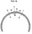
- each of the distributing passages 57 has a constriction 60 at its lower portion, as shown in Figs.15 and 16.
- a recessed groove 61 for defining each of the distributing passages 57 is defined to extend along a generatrix line, and that portion 62 of the recessed groove 61 corresponding to the constriction is narrower than a main portion 63 excluding such portion.
- a lower end of each of the constriction-correspondence portions 62 opens into upper portions b 1 of a pair of opposed inner walls of an annular groove 64 which has a U-shaped in section and opens inwards.
- Lower portion b 2 of the opposed inner walls lies on a plane extending from the annular upper end face 11 of the water-cooled casting mold 13.
- Recesses 65 for defining the discharge ports 58 are defined in the annular upper end face 11, whereby the discharge port 58 having a quadrilateral opening is defined by placing the annular lower end face 17 of the spout 15 onto a land 66 between the adjacent recessed grooves 65, as shown in Fig.15.
- Annular passages 59 each permitting the communication between each of the constrictions 60 and each of the discharge ports 58 are defined by cooperation of the annular lower end face of the cylindrical member 14, the outer peripheral surface of the lower end of the spout 15 and the outer periphery of the annular upper end face 11, and has an inner periphery which is opposed to an outer end of each of the discharge ports 58.
- the length L (mm) of each of the discharge ports 58 in the ingot-withdrawing direction is set at a value which enables the generation of a break-out to be avoided.
- the relationship between a sum A 1 (d 1 x 64) of the sectional areas d 1 (mm 2 ) of all the discharge ports 58 and a sum A 2 (d 2 x 8) of the sectional areas d 2 (mm 2 ) of all the constrictions 60 is set at A 1 > A 2
- the ratio A 2 /A 1 between the sums A 1 and A 2 of the sectional areas is set in a range of Lmin/L ⁇ A 2 /A 1 ⁇ 1 - (1/Fmax)F wherein Lmin (mm) is a minimum value of the length of the discharge port 58 in the ingot-withdrawing direction and varies depending on the capacity of the oil supply pump P; F(Hz) is a frequency for the vibration of a molten metal pressure applied to the discharge port 58 and assume
- f 1 (c/60 x (1/L)
- c an ingot-withdrawing speed (mm/min).
- c/60 means that the speed is converted into a speed per second.
- Table 4 shows the composition of an aluminum alloy used in this particular example. Chemical constituent (% by weight) Cu Si Mg Zn Fe Mn Ni Cr Ti Sr Al 4.7 7.5 0.26 0.47 0.77 0.48 0.07 0.1 0.13 0.02 balance
- an ingot I was produced in a casting manner by the above-described continuous casting apparatus without agitation of the molten metal m with the electromagnetic induction-type agitator 23 being in an non-operated state.
- the melting temperature was 730°C
- the temperature of the molten metal immediately above the spout 15 was 650°C
- the diameter of the ingot I was 152 mm
- the ingot-withdrawing speed c was variable.
- Table 5 shows the sectional area d 1 (constant) and the like of the discharge port 58 and the sectional area d 2 (variable), of the constriction 60
- Table 6 shows the sum A 1 (constant) of the sectional areas, the sum A 2 (variable) of the sectional areas and the sum ratio A 2 /A 1 .
- Ingot-withdrawing speed c (mm/min) Length L of discharge port in ingot-withdrawing direction (mm) Frequency f 1 for vibration of molten metal pressure (Hz) Ratio A 2 /A 1 of sums A 1 and A 2 of both sectional areas 0.8 0.6 0.5 0.3 0.18 0.1 100 0.05 33.3 0 0 0 0 0 0 120 40 0 0 0 0 0 140 46.7 4.1 0 0 0 0 0 160 53.3 4.3 0 0 0 0 0 180 60 5.1 0 0 0 0 0 200 66.7 6 0 0 0 0 0 0 220 73.3 6.4 0 0 0 0 0 240 80 6.9 0 0 0 0 0 0 260 86.7 7 5.1 0 0 0 0 270 90 7.1 5.3 0 0 0 0 280 93.3 7.4 5.7 0 0 0 0 290 9
- Fig.18 is a graph made by taking the frequency F on an axis of x of rectangular coordinates and taking the ratio A 2 /A 1 of the sums A 1 and A 2 of both the sectional areas on an axis of y of the rectangular coordinates, connecting a limit point of the ratio A 2 /A 1 and a limit point of the frequency F to each other, and plotting the relationship between the ratio A 2 /A 1 when the number of roughened portions of the casting skin in the ingot I is zero, and the maximum value of the frequency F on the basis of Tables 7 and 8.
- the casting operation was carried out with the length L of the discharge ports 58 in the ingot-withdrawing direction set as a variable under conditions of an ingot withdrawing speed
- the lower limit value of the ratio A 2 /A 1 is set to be equal to Lmin/L, in order to ensure that the roughening of the casting skin of the ingot I is not produced.
- the minimum value Lmin is equal to 0.0045 mm from the relationship to the capacity of the supply pump P.
- Fig.19 shows the ratio A 2 /A 1 equal to 0.0045/L, when the length L of the discharge port 58 in the ingot withdrawing direction is taken on an axis of x and the ratio A 2 /A 1 of the sums A 1 and A 2 of both the sectional areas is taken on an axis of y in a rectangular coordinates. Therefore, the ratio A 2 /A 1 is set in a range of the ratio A 2 /A 1 ⁇ Lmin/L .
- the lubricating oil is vaporized in an opened end of each of the discharge port 58 to generate a gas.
- this gas enters the lubricating oil supply passageway F L and is not discharged therefrom smoothly, the passageway F L is clogged with the lubricating oil, resulting in a reduction in quality of the appearance of the ingot I due to the roughening of the casting surface.
- the gas enters the molten metal m , the quality of the appearance of the ingot I due to the generation of voids.
- Such behavior of the gas depends on the gradient of each of the discharge ports 58.
- the gradient of each of the discharge ports 58 with respect to the ingot withdrawing direction a 1 as shown in Fig.20 is determined in the following manner:
- the angle ⁇ formed by the center line g with respect to the horizontal line j is determined within a range of 45° upwards from the horizontal line j and 15° downwards from the horizontal line j . This applies to the case where the molten metal m is agitated and the case where the molten metal m is not agitated.
- the gradient of each discharge port 58 in a direction a 2 of rotation of the molten metal m as shown in Fig.21 is determined in the following manner:
- a plurality of reference lines o intersecting the axis n of the cylindrical casting mold 13 in correspondence to the center line of each discharge port 58 are drawn in a horizontal plane k including the center line g of each discharge port 58, as perspectively viewed from above, the angle ⁇ formed by each of the center lines g with respect to each of the reference lines o is determined within a range of 30° forwards in the direction a 2 of rotation of the molten metal from the reference line o and 15° backwards in the direction a 2 of rotation of the molten metal from the reference line o .
- This is applied to the discharge port 58 in which the center line g is horizontal in the vertical plane h in Fig.20, and the discharge port 58 in which the center line
- An ingot I made of a light alloy is produced using a continuous casting apparatus including a cylindrical water-cooled casting mold which is disposed immediately below a spout having an upward-turned molten metal receiving port and a downward-turned molten metal outlet, and which has an inside radius r 1 larger than an inside radius r 2 of the molten metal outlet, and lubricating oil discharge passages provided below the spout to supply a lubricating oil to between the water-cooled casting mold 13 and a molten metal m brought into contact with the water-cooled casting mold.
- a lubricating oil having a vaporization rate of 30 % or more at 300° is used, and an annular gas accumulation for spacing the molten metal apart from outlets of the lubricating oil discharge passages is defined below an annular protrusion of the spout by vaporization of the lubricating oil.
Landscapes
- Engineering & Computer Science (AREA)
- Mechanical Engineering (AREA)
- Continuous Casting (AREA)
Priority Applications (1)
| Application Number | Priority Date | Filing Date | Title |
|---|---|---|---|
| ARP000101078 AR022904A1 (es) | 1999-03-12 | 2000-03-10 | BANDA DE DESHIDRATACIoN, ESPECIALMENTE TAMIZ DE SECADO. |
Applications Claiming Priority (6)
| Application Number | Priority Date | Filing Date | Title |
|---|---|---|---|
| JP6350698 | 1998-03-13 | ||
| JP6350698 | 1998-03-13 | ||
| JP18605898 | 1998-07-01 | ||
| JP18605898A JP3000452B1 (ja) | 1998-07-01 | 1998-07-01 | 連続鋳造装置 |
| JP10256929A JP3008280B2 (ja) | 1998-03-13 | 1998-09-10 | 軽合金の連続鋳造法および軽合金用連続鋳造装置 |
| JP25692998 | 1998-09-10 |
Publications (2)
| Publication Number | Publication Date |
|---|---|
| EP0941786A1 true EP0941786A1 (de) | 1999-09-15 |
| EP0941786B1 EP0941786B1 (de) | 2004-01-21 |
Family
ID=27298195
Family Applications (1)
| Application Number | Title | Priority Date | Filing Date |
|---|---|---|---|
| EP99104936A Expired - Lifetime EP0941786B1 (de) | 1998-03-13 | 1999-03-12 | Verfahren und Vorrichtung zur Schmierung beim kontinuierlichen Giessen von Leichtmetallen |
Country Status (3)
| Country | Link |
|---|---|
| US (1) | US6840303B1 (de) |
| EP (1) | EP0941786B1 (de) |
| DE (1) | DE69914239T2 (de) |
Cited By (1)
| Publication number | Priority date | Publication date | Assignee | Title |
|---|---|---|---|---|
| EP1611979A1 (de) * | 2004-06-29 | 2006-01-04 | Alcoa Inc. | Gesteuerte Strömungsgiessform und Verfahren zum Giessen einer Metallschmelze |
Citations (8)
| Publication number | Priority date | Publication date | Assignee | Title |
|---|---|---|---|---|
| DE1067571B (de) * | 1956-10-22 | 1959-10-22 | Dow Chemical Co | Giessformenschmiermittel fuer das kontinuierliche Giessen leicht oxydierbarer Metalle |
| AT264739B (de) * | 1965-07-24 | 1968-09-10 | Vaw Ver Aluminium Werke Ag | Verfahren und Einrichtung zur Zuführung des Schmiermittels beim vollkontinuierlichen Gießen von Metallen in stationären Kokillen |
| US4157728A (en) * | 1976-07-29 | 1979-06-12 | Showa Denko Kabushiki Kaisha | Process for direct chill casting of metals |
| DE3338185A1 (de) * | 1982-10-20 | 1984-05-03 | Wagstaff Engineering Inc., Spokane, Wash. | Verfahren und vorrichtung zum giessen von metallen |
| US4522250A (en) * | 1982-12-29 | 1985-06-11 | Aluminum Company Of America | Continuous casting with glycerol trioleate parting composition |
| EP0218855A1 (de) * | 1985-09-20 | 1987-04-22 | Vereinigte Aluminium-Werke Aktiengesellschaft | Verfahren und Vorrichtung zum Stranggiessen |
| EP0337769A2 (de) * | 1988-04-15 | 1989-10-18 | Norsk Hydro A/S | Kontinuierliche oder halbkontinuierliche Giesseinrichtung für das Giessen metallischen Materials |
| EP0372946A2 (de) * | 1988-12-08 | 1990-06-13 | Alcan International Limited | Schmierung von Stranggiesskokillen |
Family Cites Families (3)
| Publication number | Priority date | Publication date | Assignee | Title |
|---|---|---|---|---|
| US4214624A (en) * | 1978-10-26 | 1980-07-29 | Kaiser Aluminum & Chemical Corporation | Method of and mold for DC casting |
| US5027888A (en) * | 1989-01-31 | 1991-07-02 | Hitachi Zosen Corporation | Method and apparatus for sealing molten metal for a twin-roll type continous casting apparatus |
| FR2656552B1 (fr) * | 1990-01-04 | 1995-01-13 | Pechiney Aluminium | Procede de fabrication de produits metalliques thixotropes par coulee continue avec brassage electromagnetique en courant polyphase. |
-
1999
- 1999-03-12 EP EP99104936A patent/EP0941786B1/de not_active Expired - Lifetime
- 1999-03-12 US US09/266,870 patent/US6840303B1/en not_active Expired - Fee Related
- 1999-03-12 DE DE69914239T patent/DE69914239T2/de not_active Expired - Fee Related
Patent Citations (9)
| Publication number | Priority date | Publication date | Assignee | Title |
|---|---|---|---|---|
| DE1067571B (de) * | 1956-10-22 | 1959-10-22 | Dow Chemical Co | Giessformenschmiermittel fuer das kontinuierliche Giessen leicht oxydierbarer Metalle |
| AT264739B (de) * | 1965-07-24 | 1968-09-10 | Vaw Ver Aluminium Werke Ag | Verfahren und Einrichtung zur Zuführung des Schmiermittels beim vollkontinuierlichen Gießen von Metallen in stationären Kokillen |
| US4157728A (en) * | 1976-07-29 | 1979-06-12 | Showa Denko Kabushiki Kaisha | Process for direct chill casting of metals |
| US4157728B1 (de) * | 1976-07-29 | 1987-06-09 | ||
| DE3338185A1 (de) * | 1982-10-20 | 1984-05-03 | Wagstaff Engineering Inc., Spokane, Wash. | Verfahren und vorrichtung zum giessen von metallen |
| US4522250A (en) * | 1982-12-29 | 1985-06-11 | Aluminum Company Of America | Continuous casting with glycerol trioleate parting composition |
| EP0218855A1 (de) * | 1985-09-20 | 1987-04-22 | Vereinigte Aluminium-Werke Aktiengesellschaft | Verfahren und Vorrichtung zum Stranggiessen |
| EP0337769A2 (de) * | 1988-04-15 | 1989-10-18 | Norsk Hydro A/S | Kontinuierliche oder halbkontinuierliche Giesseinrichtung für das Giessen metallischen Materials |
| EP0372946A2 (de) * | 1988-12-08 | 1990-06-13 | Alcan International Limited | Schmierung von Stranggiesskokillen |
Cited By (1)
| Publication number | Priority date | Publication date | Assignee | Title |
|---|---|---|---|---|
| EP1611979A1 (de) * | 2004-06-29 | 2006-01-04 | Alcoa Inc. | Gesteuerte Strömungsgiessform und Verfahren zum Giessen einer Metallschmelze |
Also Published As
| Publication number | Publication date |
|---|---|
| EP0941786B1 (de) | 2004-01-21 |
| DE69914239D1 (de) | 2004-02-26 |
| US6840303B1 (en) | 2005-01-11 |
| DE69914239T2 (de) | 2004-06-17 |
Similar Documents
| Publication | Publication Date | Title |
|---|---|---|
| US5325910A (en) | Method and apparatus for continuous casting | |
| EP0265235A2 (de) | Stranggiessen von Verbundmetall | |
| EP0941786B1 (de) | Verfahren und Vorrichtung zur Schmierung beim kontinuierlichen Giessen von Leichtmetallen | |
| CN1318164C (zh) | 在连续浇铸结晶器中、尤其在铸造液面处的热传导的匹配 | |
| US4653571A (en) | Method for horizontal continuous casting of a metal, where the lower mold/cast metal contact point is horizontally displaced | |
| EP0657235B1 (de) | Verfahren zur Herstellung thixotroper Metalllegierungen | |
| KR20100097702A (ko) | 주탕용 노즐 및 연속 주조 장치 | |
| JPS6133735A (ja) | 金属の水平連続鋳造方法および装置 | |
| JPS63104751A (ja) | 金属の水平連続鋳造法及び装置 | |
| KR20010051510A (ko) | 연속주조 주형의 열방출을 감소시키기 위한 방법 및 장치 | |
| EP0940204B1 (de) | Vorrichtung zum Stranggiessen mit Badbewegung | |
| US5379828A (en) | Apparatus and method for continuous casting of molten steel | |
| JP3008280B2 (ja) | 軽合金の連続鋳造法および軽合金用連続鋳造装置 | |
| JP3400355B2 (ja) | 攪拌連続鋳造装置 | |
| JPS6021157A (ja) | 薄板連続鋳造装置 | |
| JP3000452B1 (ja) | 連続鋳造装置 | |
| US5494095A (en) | Apparatus for continuous casting of molten steel | |
| EP0947262B1 (de) | Verfahren zum Stranggiessen von Aluminiumlegierungen mit Rührwirkung | |
| AU783071B2 (en) | Mold with a function ring | |
| US4744406A (en) | Horizontal continuous casting apparatus with break ring formed integral with mold | |
| JPH02295642A (ja) | 水平連続鋳造装置 | |
| JPS6021159A (ja) | 薄板連続鋳造装置 | |
| JPS6171157A (ja) | 金属の水平連続鋳造法および装置 | |
| JPS61154736A (ja) | 水平連続鋳造装置 | |
| CA2101282C (en) | Apparatus and method for continuous casting of molten steel |
Legal Events
| Date | Code | Title | Description |
|---|---|---|---|
| PUAI | Public reference made under article 153(3) epc to a published international application that has entered the european phase |
Free format text: ORIGINAL CODE: 0009012 |
|
| AK | Designated contracting states |
Kind code of ref document: A1 Designated state(s): DE FR GB |
|
| AX | Request for extension of the european patent |
Free format text: AL;LT;LV;MK;RO;SI |
|
| 17P | Request for examination filed |
Effective date: 19990903 |
|
| AKX | Designation fees paid |
Free format text: DE FR GB |
|
| 17Q | First examination report despatched |
Effective date: 20021018 |
|
| GRAH | Despatch of communication of intention to grant a patent |
Free format text: ORIGINAL CODE: EPIDOS IGRA |
|
| GRAS | Grant fee paid |
Free format text: ORIGINAL CODE: EPIDOSNIGR3 |
|
| GRAA | (expected) grant |
Free format text: ORIGINAL CODE: 0009210 |
|
| AK | Designated contracting states |
Kind code of ref document: B1 Designated state(s): DE FR GB |
|
| REG | Reference to a national code |
Ref country code: GB Ref legal event code: FG4D |
|
| REF | Corresponds to: |
Ref document number: 69914239 Country of ref document: DE Date of ref document: 20040226 Kind code of ref document: P |
|
| ET | Fr: translation filed | ||
| PLBE | No opposition filed within time limit |
Free format text: ORIGINAL CODE: 0009261 |
|
| STAA | Information on the status of an ep patent application or granted ep patent |
Free format text: STATUS: NO OPPOSITION FILED WITHIN TIME LIMIT |
|
| 26N | No opposition filed |
Effective date: 20041022 |
|
| PGFP | Annual fee paid to national office [announced via postgrant information from national office to epo] |
Ref country code: FR Payment date: 20050308 Year of fee payment: 7 |
|
| REG | Reference to a national code |
Ref country code: FR Ref legal event code: ST Effective date: 20061130 |
|
| PG25 | Lapsed in a contracting state [announced via postgrant information from national office to epo] |
Ref country code: FR Free format text: LAPSE BECAUSE OF NON-PAYMENT OF DUE FEES Effective date: 20060331 |
|
| PGFP | Annual fee paid to national office [announced via postgrant information from national office to epo] |
Ref country code: GB Payment date: 20080312 Year of fee payment: 10 |
|
| PGFP | Annual fee paid to national office [announced via postgrant information from national office to epo] |
Ref country code: DE Payment date: 20090306 Year of fee payment: 11 |
|
| GBPC | Gb: european patent ceased through non-payment of renewal fee |
Effective date: 20090312 |
|
| PG25 | Lapsed in a contracting state [announced via postgrant information from national office to epo] |
Ref country code: GB Free format text: LAPSE BECAUSE OF NON-PAYMENT OF DUE FEES Effective date: 20090312 |
|
| PG25 | Lapsed in a contracting state [announced via postgrant information from national office to epo] |
Ref country code: DE Free format text: LAPSE BECAUSE OF NON-PAYMENT OF DUE FEES Effective date: 20101001 |