EP0219897A1 - Dispositif d'acquisition d'image rayons X par photoconducteur - Google Patents
Dispositif d'acquisition d'image rayons X par photoconducteur Download PDFInfo
- Publication number
- EP0219897A1 EP0219897A1 EP86201662A EP86201662A EP0219897A1 EP 0219897 A1 EP0219897 A1 EP 0219897A1 EP 86201662 A EP86201662 A EP 86201662A EP 86201662 A EP86201662 A EP 86201662A EP 0219897 A1 EP0219897 A1 EP 0219897A1
- Authority
- EP
- European Patent Office
- Prior art keywords
- photoconductor
- carrier
- cylinder axis
- ray
- charge
- Prior art date
- Legal status (The legal status is an assumption and is not a legal conclusion. Google has not performed a legal analysis and makes no representation as to the accuracy of the status listed.)
- Granted
Links
- 239000000523 sample Substances 0.000 claims abstract description 32
- 230000005855 radiation Effects 0.000 claims abstract description 15
- 206010022000 influenza Diseases 0.000 claims description 21
- 238000006073 displacement reaction Methods 0.000 claims description 8
- 230000002093 peripheral effect Effects 0.000 claims description 3
- 229910052711 selenium Inorganic materials 0.000 description 41
- 239000011669 selenium Substances 0.000 description 41
- BUGBHKTXTAQXES-UHFFFAOYSA-N Selenium Chemical compound [Se] BUGBHKTXTAQXES-UHFFFAOYSA-N 0.000 description 40
- 238000009826 distribution Methods 0.000 description 10
- OAICVXFJPJFONN-UHFFFAOYSA-N Phosphorus Chemical compound [P] OAICVXFJPJFONN-UHFFFAOYSA-N 0.000 description 3
- 239000002800 charge carrier Substances 0.000 description 3
- 238000013461 design Methods 0.000 description 3
- 230000002349 favourable effect Effects 0.000 description 3
- 238000010521 absorption reaction Methods 0.000 description 2
- 230000008859 change Effects 0.000 description 2
- 238000011161 development Methods 0.000 description 2
- 238000004519 manufacturing process Methods 0.000 description 2
- 229910052751 metal Inorganic materials 0.000 description 2
- 239000002184 metal Substances 0.000 description 2
- 230000004048 modification Effects 0.000 description 2
- 238000012986 modification Methods 0.000 description 2
- 238000002601 radiography Methods 0.000 description 2
- 238000005019 vapor deposition process Methods 0.000 description 2
- 229910052782 aluminium Inorganic materials 0.000 description 1
- XAGFODPZIPBFFR-UHFFFAOYSA-N aluminium Chemical compound [Al] XAGFODPZIPBFFR-UHFFFAOYSA-N 0.000 description 1
- 230000008901 benefit Effects 0.000 description 1
- 230000008878 coupling Effects 0.000 description 1
- 238000010168 coupling process Methods 0.000 description 1
- 238000005859 coupling reaction Methods 0.000 description 1
- 230000007423 decrease Effects 0.000 description 1
- 230000003247 decreasing effect Effects 0.000 description 1
- 230000008020 evaporation Effects 0.000 description 1
- 238000001704 evaporation Methods 0.000 description 1
- 230000006870 function Effects 0.000 description 1
- 238000003384 imaging method Methods 0.000 description 1
- 229910000464 lead oxide Inorganic materials 0.000 description 1
- 238000000034 method Methods 0.000 description 1
- 239000000615 nonconductor Substances 0.000 description 1
- YEXPOXQUZXUXJW-UHFFFAOYSA-N oxolead Chemical compound [Pb]=O YEXPOXQUZXUXJW-UHFFFAOYSA-N 0.000 description 1
- 230000008569 process Effects 0.000 description 1
- 238000012545 processing Methods 0.000 description 1
- 125000003748 selenium group Chemical group *[Se]* 0.000 description 1
- 239000000758 substrate Substances 0.000 description 1
- 230000001360 synchronised effect Effects 0.000 description 1
- 238000013519 translation Methods 0.000 description 1
- 238000007740 vapor deposition Methods 0.000 description 1
Images

Classifications
-
- G—PHYSICS
- G01—MEASURING; TESTING
- G01T—MEASUREMENT OF NUCLEAR OR X-RADIATION
- G01T1/00—Measuring X-radiation, gamma radiation, corpuscular radiation, or cosmic radiation
- G01T1/29—Measurement performed on radiation beams, e.g. position or section of the beam; Measurement of spatial distribution of radiation
- G01T1/2914—Measurement of spatial distribution of radiation
- G01T1/2964—Scanners
-
- G—PHYSICS
- G01—MEASURING; TESTING
- G01T—MEASUREMENT OF NUCLEAR OR X-RADIATION
- G01T1/00—Measuring X-radiation, gamma radiation, corpuscular radiation, or cosmic radiation
- G01T1/29—Measurement performed on radiation beams, e.g. position or section of the beam; Measurement of spatial distribution of radiation
- G01T1/2914—Measurement of spatial distribution of radiation
- G01T1/2921—Static instruments for imaging the distribution of radioactivity in one or two dimensions; Radio-isotope cameras
Definitions
- the invention relates to an arrangement for generating X-ray images by means of an X-radiation converting a photoconductor into a charge pattern, with a charging device for locally uniform charging of the surface of the photoconductor and with a scanning device which, in order to translate the charge density at different points on the surface of the photoconductor, has a plurality arranged in a row Contains influenza probes.
- a charging device for locally uniform charging of the surface of the photoconductor
- a scanning device which, in order to translate the charge density at different points on the surface of the photoconductor, has a plurality arranged in a row Contains influenza probes.
- Such an arrangement is essentially known from DE-OS 29 48 660 and from US-PS 4, 134, 137 - there, however, only in connection with a single influenza probe.
- a photoconductor is usually a non-conductor. However, if it is exposed to X-rays, its conductivity increases during the irradiation at the irradiated points, so that the charge density generated by a previous charge is reduced at these points, and the more so, the greater the intensity of the X-ray radiation and the more the longer it acts on the photoconductor, ie the larger the dose at the point in question.
- the two-dimensional charge pattern produced in this way on the surface of the photoconductor which essentially corresponds to the spatial distribution of the X-ray intensity, is converted into electrical signals by the scanning device. These are amplified, filtered, digitized and saved in a memory. They are then accessible to digital image processing.
- the photoconductor is applied to a flat carrier. After the X-ray exposure, the charge distribution must be read out with the aid of the scanning device, which must be guided in a meandering manner or in a similar manner over the surface of the photoconductor.
- the photoconductor not only discharges during the X-ray exposure, but also before and after it. In order to keep the resulting errors small, it is necessary that the time between the end of charging and the end of the scan, in particular also between the X-ray exposure and the end of the scan, is made as short as possible. This is e.g. meandering scanning hardly possible.
- a quick scan could be achieved if there were so many influenza probes in the scanner that the charge distributions at the pixels of an entire line of an x-ray image could be recorded simultaneously, but the manufacture of such a scanner with one that is also sufficient for scanning larger x-rays is sufficient Number of influenza probes not yet satisfactorily successful.
- the amplitude of the signal delivered by the influenza probe depends not only on the charge density at the location scanned, but also on the distance between the surface of the photoconductor and the influenza probe. Even a change in distance of just a few ⁇ m results in a significant falsification of the signal. During the scanning of the surface of the photoconductor by the scanning device, it is therefore necessary that the distance between the influenza probes remains largely constant. This results in extreme demands for the mechanics of the scanning device and for the flatness of the photoconductor layer.
- the photoconductor is applied to the outer jacket of a circular cylindrical carrier, that the X-radiation strikes the photoconductor through at least one slit-shaped diaphragm, the main direction of expansion of which extends parallel to the cylinder axis of the carrier, that a drive device for rotating the carrier the cylinder axis and for shifting the masked beam fan relative to the examination area is provided synchronously with the rotation of the carrier, that the influenza probes are arranged offset relative to one another in the direction of the cylinder axis, that the drive device rotates the carrier further after the X-ray exposure and that the charging device is designed in such a way that it can charge the photoconductor along its entire length in the direction of the cylinder axis.
- the photoconductor is therefore applied to the outer jacket of a circular cylindrical support.
- a cylindrical support with an exactly circular cross-section is, however, much easier to manufacture than an exactly flat support.
- a uniformly thick photoconductor layer in particular by vapor deposition, can be applied to such a carrier much more easily than to a flat carrier because the carrier can be rotated about its axis during the vapor deposition process, so that a uniformly thick selenium layer results on its circumference. For this reason and because the scanning of the charge distribution in the circumferential direction of the carrier only requires one rotation of the carrier the charge distribution on the surface of the photoconductor is recorded much more precisely and much faster than with a flat photoconductor.
- the complete scanning of the surface of the photoconductor requires only the displacement of the influence probes in one direction and not, as in the case of a flat plate, in two directions perpendicular to one another.
- the charging takes place in that the charging device is activated before a picture is taken and the carrier is rotated so that the surface of the photoconductor is charged line by line during the rotation (the lines run parallel to the axis of rotation or to the cylinder axis).
- the gas is ionized and the charge carriers generated are accelerated onto a dielectric film which is attached either to the inner surface of the outer electrode or to the outer surface of the inner electrode. This results in a charge distribution on the dielectric film which, after removal, can be converted into a visible image in a known manner.
- the cylindrical design of the electrodes is intended to create an arrangement which is strong enough on the one hand to keep the electrode spacing uniform everywhere at the required high gas pressure and on the other hand is sufficiently thin to allow the entry of X-rays into the gas volume.
- EP-OS 0 094 843 discloses an arrangement for generating X-ray images in which a stimulable phosphor is applied to the outer jacket of a circular cylindrical carrier and in which a drive device for rotating the carrier about the cylinder axis is provided.
- the stimulable phosphor is excited by the X-ray exposure, so that when scanned with a laser it emits light whose intensity corresponds to the intensity of the X-ray radiation.
- the stimulable phosphor is attached to the support in three or four sections, one of which is exposed during each exposure, namely all the pixels of the exposure at the same time. After the recording, this section is brought into a position by rotating the carrier, in which it can be read out by means of a laser and a deflection mirror.
- a further development of the invention which is based on a scanning device which has significantly fewer influenza probes than a line of pixels, provides that a device for displacing the scanning device parallel to Cylinder axis is provided and that the mean value of the displacement speed is small compared to the peripheral speed of the carrier.
- the carrier must make N complete rotations, where N is the ratio between the number of pixels in a line and the number of influence probes.
- N is the ratio between the number of pixels in a line and the number of influence probes.
- the displacement of the scanning device in the direction of the cylinder axis can take place in steps or continuously. With the gradual shift, each probe scans the surface of the photoconductor on parallel circular paths. With this type of scanning, however, it is disadvantageous that the scanning device must be accelerated and then decelerated again with each shifting step. In this regard, the continuous shift in which the surface of each probe is scanned along a helical path is more favorable.
- the influencing probes of the scanning device are distributed uniformly over the photoconductor in the axial direction of the carrier. In order to be able to completely capture the surface of the photoconductor, it is only necessary to shift the scanning device in the axial direction by the distance between two influenza probes (while the cylindrical carrier executes N rotations).
- a further development of the invention provides that the rotational speed of the carrier after the X-ray exposure is significantly greater than during the X-ray exposure.
- the speed of the X-ray exposure is limited by the intensity of the X-ray radiation. However, this limitation does not apply during the scanning of the charge density on the surface of the photoconductor following one X-ray exposure.
- the higher speed results in a higher readout speed; however, this presupposes that the influenza probes and the electronics connected to them can still process the resulting frequencies.
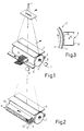
- an X-ray source is designated by 1, for example an X-ray tube, of which only the focus from which the X-rays emanate is shown in FIG.
- a first diaphragm 3 is arranged in the beam path of the radiation source 1 and has a rectilinear slit-shaped opening for the X-rays. Through this opening of the diaphragm, a fan-shaped X-ray beam is faded out, which passes through the examination area (not shown in more detail). After passing through the examination area, the x-ray beam passes through a further aperture 5 with a likewise slit-shaped opening, which is shaped such that it practically coincides with the projection of the slit-shaped opening in the aperture 3 through the x-ray source.
- the X-ray radiation passing through the slit-shaped opening in the diaphragm 5 strikes the apex line of a selenium drum 6.
- the selenium drum 6 contains one cylindrical carrier body made of metal, for example aluminum, which, as indicated schematically, can be rotated about its axis by means of a drive motor 7 which is adjustable in speed.
- An approximately 500 ⁇ m thick amorphous selenium layer is applied to the outer jacket of this carrier, which can be produced by evaporation with great uniformity if the carrier body is rotated about its axis during the vapor deposition process.
- the drum has dimensions suitable for taking an X-ray image, for example a length of 400 mm and a diameter of 150 mm.
- another photoconductor could also be used, for example lead oxide; However, selenium is preferred.
- An X-ray image with such an arrangement is generated in three phases at short intervals in succession:
- a charging device 9 extending over the entire length of the drum 6 and parallel to the axis of rotation 8 is provided.
- the charging device comprises a grounded rail 9l made of metal with a U-shaped cross section open to the drum 6.
- a thin wire 92 - possibly also a plurality of thin wires - is arranged within the rail and carries a potential of, for example, 5 kV.
- the rail is closed towards the selenium drum 6 by a grid 93, which has a comparatively low negative bias of, for example, -60 V compared to the rail 91. The whole thing is arranged in the immediate vicinity of the selenium drum.
- the operating voltage of the wire 92 is switched on and the selenium drum 6 is rotated.
- the carrier 6l of the selenium drum is applied to a voltage which gradually increases to a value of e.g. -l. 500 V is increased.
- the positive charge carriers generated by the high field strength in the immediate vicinity of the wire 92 are accelerated by the high negative bias of the carrier 61 through the grid 93 until they reach the selenium layer 62 on the carrier and charge it.
- This charging of the selenium layer ends when the charge density is so large that the charge carriers generated only reach the grid 93 or the rail 91.
- the potential on the surface of the selenium layer is then about 0 V. As a result of the rotation of the carrier, the entire surface is charged after a few revolutions.
- the radiation source 1 is switched on.
- the drum 7 is rotated at a certain speed, for example one revolution per second, and at the same time, as indicated by the arrows, the unit 1, 3, 5, 6 is moved at a speed which depends on the speed of the selenium drum 6.
- the speed at which the x-ray beam is moved relative to the examination area must be selected so that the x-ray projection of a point in the examination area always coincides with the same point on the surface of the drum. - If workpieces are to be examined with the device instead of a patient, it is also possible to leave the unit 1, 3, 5, 6 stationary and to move the workpiece at the appropriate speed, but in the opposite direction.
- the level of the discharge and thus the amplitude of the signals supplied by the scanning device to be described depends not only on the intensity of the X-rays and their absorption in the examination area, but also on how long the surface is exposed to the X-rays. This time period can be increased by a low speed of rotation of the selenium drum, however, the duration of the X-ray exposure and then the load on the X-ray source would increase.
- a cheaper option for increasing the exposure time of the individual sections on the drum is to broaden the fan-shaped beam (by widening the slit-shaped openings in diaphragms 3 and 5).
- the projection of a point in the examination area onto the selenium drum changes its position on the selenium drum, so that the spatial resolution decreases.
- the width of the slit-shaped openings in the diaphragms 3 and 5 can be chosen such that an up to 2 cm wide strip on the surface of the selenium drum by the X-rays is exposed so that each point on the surface of the selenium drum is exposed for about 40 ms (at a speed of the selenium drum of 60 revolutions per minute). This is a significant advantage over arrangements for slit or split radiography with a single detector line, in which only a single image line - the detector line - is exposed.
- the X-rays are switched off again.
- the voltage on the wire 92 and on the grid 93 of the charging device 9 is switched off, while the carrier 6l continues to carry a voltage of -1,500 V to ground.
- the charge density or the surface potential at the individual points of the selenium layer 62 is then proportional to the X-ray dose.
- This charge density is detected with the aid of a scanning device, which comprises a plurality of influenza probes located on a straight line parallel to the cylinder axis 8 at a short distance from the drum surface, which generate an electrical signal corresponding to the charge density on the surface, while simultaneously rotating the selenium drum - preferably with one opposite the exposure increased speed, e.g. 600 revolutions per minute.
- the scanning device contained as many influenza probes in a row as there are pixels in an image line. After one revolution of the selenium drum, ie after 0.1 sec, the entire charge distribution could then have been recorded. If one realizes, however, that an image line can have approximately 2,048 pixels, then the scanning device on a 40 cm long row should contain 2,048 influenza probes next to one another. Such scanning devices can hardly be manufactured with reasonable effort.
- the arrangement according to FIG. 1 therefore comprises a substrate which is short compared to the length of the selenium drum and on which a plurality of probe electrodes are arranged at a close distance from one another.
- a scanning device is known from DE-OS 29 48 660. During one revolution of the selenium drum, however, it can only detect the charge density distribution on a section that corresponds to its length.
- the scanning device comprises a guide rail 12 which runs parallel to the cylinder axis and on which the influence probes 11 can be displaced by means of a motor 13.
- the influenza probes have to be moved step by step or continuously and practically over the entire length of the drum over a large number of revolutions.
- influenza probes III for example 32
- the influenza probes form, together with the preamplifier electronics arranged on a circuit board II2, closed units which are adjusted in a common frame II3.
- This frame is continuously displaced parallel to the cylinder axis during the image acquisition by means of the guide rail 12 and the drive motor (not shown in more detail).
- the entire displacement distance corresponds to the distance between two influenza probes.
- the charge density on the entire surface of the selenium drum can thus be recorded with approx. 64 revolutions with a picture element size of 200 ⁇ 200 ⁇ m2, which results in a readout time of only around 6 seconds at the specified speed.
- the drum 9 is coupled to an incremental angle encoder (not shown) with a correspondingly high resolution, which generates an electrical signal corresponding to the respective rotational position of the drum.
- a suitable position transmitter must also be provided to determine the position of the unit II in the axial direction.
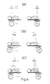
- 4a to 4c indicate various possibilities of how the x-ray fan can be shifted during the x-ray exposure relative to the examination area - here symbolized by a patient 4.
- the radiation source 1, the diaphragms 3 and 5 and the drum 6 are firmly connected to one another and move in a straight line at the same speed perpendicular to the beam fan.
- the disadvantage here is that the x-ray source 1 usually has to be moved relatively quickly over a relatively large distance an x-ray tube attached to a tripod with a not inconsiderable mass.
- the arrangement shown in FIG. 4b is more favorable, in which the radiation source 1, the diaphragms 3 and 5 and the selenium drum are coupled to one another via a pendulum rod which is pivoted during the exposure about a pivot axis running through the focal spot.
- the X-ray tube only needs to be pivoted, but not moved in translation.
- the selenium drum is moved on a circular path and the distance between the object to be examined and the selenium drum varies greatly.
- the radiation source likewise does not change its position, but the diaphragms 3, 5 and the selenium drum 6 are moved in a straight line and at speeds proportional to their distance from the focal spot. If the distance between the diaphragm 5 and the apex of the selenium drum 6 is small, both parts can be moved at the same speed, so that the diaphragm 5 can be firmly coupled to the holder of the selenium drum 6.
- FIG. 5 shows a correspondingly constructed X-ray examination device.
- the radiation source l - an x-ray tube - is pivotally attached to a vertical column 2 about a horizontal pivot axis perpendicular to the plane of the drawing, which runs through the focal spot 10l of the x-ray tube.
- Below the x-ray emitter is an aperture arrangement 3 with a slit-shaped opening, the main direction of expansion of which extends perpendicular to the plane of the drawing in FIG. This is located on an examination table l4, which is pivotally attached to a device base l6.
- a carriage l7 which is provided on its top with a slot-shaped opening for the fan-shaped beam, under which the selenium drum 6 is rotatably arranged.
- the charging device 9 and the scanning device 11 and — not shown in more detail — the components 7, 12 and 13 (FIG. 1) are also attached to the carriage 17.
- the carriage can be moved by means of a motor 18 from the starting position shown in solid lines to the end position shown in dashed lines.
- the driving speed corresponds exactly to the peripheral speed of the drum surface.
- the carriage l7 is coupled via a coupling rod l9 to the x-ray emitter l, so that it moves when the Wagens is pivoted about an axis extending through the focal point l0l.
- the hatched area of the patient 4 is penetrated by X-rays.
- sharp imaging requires that the traveling speed of the carriage 17 and the speed at which a point on the surface of the selenium drum moves about the axis of rotation 8 are the same.
- the drive motor 18 for the car and the drive motor 7 for the selenium drum must therefore be electronically synchronized so that this condition is always met.
Landscapes
- Spectroscopy & Molecular Physics (AREA)
- Health & Medical Sciences (AREA)
- Life Sciences & Earth Sciences (AREA)
- General Physics & Mathematics (AREA)
- High Energy & Nuclear Physics (AREA)
- Molecular Biology (AREA)
- Physics & Mathematics (AREA)
- Radiography Using Non-Light Waves (AREA)
- Facsimile Scanning Arrangements (AREA)
- Exposure Or Original Feeding In Electrophotography (AREA)
- Combination Of More Than One Step In Electrophotography (AREA)
- Apparatus For Radiation Diagnosis (AREA)
- Analysing Materials By The Use Of Radiation (AREA)
- Transforming Light Signals Into Electric Signals (AREA)
Applications Claiming Priority (2)
| Application Number | Priority Date | Filing Date | Title |
|---|---|---|---|
| DE3534768 | 1985-09-30 | ||
| DE19853534768 DE3534768A1 (de) | 1985-09-30 | 1985-09-30 | Anordnung zum erzeugen von roentgenaufnahmen mittels eines fotoleiters |
Publications (2)
| Publication Number | Publication Date |
|---|---|
| EP0219897A1 true EP0219897A1 (fr) | 1987-04-29 |
| EP0219897B1 EP0219897B1 (fr) | 1989-11-29 |
Family
ID=6282306
Family Applications (1)
| Application Number | Title | Priority Date | Filing Date |
|---|---|---|---|
| EP86201662A Expired EP0219897B1 (fr) | 1985-09-30 | 1986-09-24 | Dispositif d'acquisition d'image rayons X par photoconducteur |
Country Status (3)
| Country | Link |
|---|---|
| EP (1) | EP0219897B1 (fr) |
| JP (1) | JPS6283772A (fr) |
| DE (2) | DE3534768A1 (fr) |
Cited By (5)
| Publication number | Priority date | Publication date | Assignee | Title |
|---|---|---|---|---|
| EP0318807A1 (fr) * | 1987-12-01 | 1989-06-07 | Noranda Inc. | Système de mesure de distribution de charge sur une surface photoréceptrice |
| EP0379748A1 (fr) * | 1988-12-17 | 1990-08-01 | Philips Patentverwaltung GmbH | Méthode et dispositif d'acquisition d'image aux rayons X par photoconducteur |
| US5093851A (en) * | 1990-05-11 | 1992-03-03 | U.S. Philips Corporation | Device for producing x-ray pictures |
| EP0558116A1 (fr) * | 1992-02-22 | 1993-09-01 | Philips Patentverwaltung GmbH | Procédé pour radiographies et dispositif approprié |
| US5357549A (en) * | 1990-10-24 | 1994-10-18 | U.S. Philips Corporation | Method of dynamic range compression of an X-ray image and apparatus effectuating the method |
Families Citing this family (5)
| Publication number | Priority date | Publication date | Assignee | Title |
|---|---|---|---|---|
| JPH01241536A (ja) * | 1988-03-23 | 1989-09-26 | Hitachi Ltd | X線画像検出装置 |
| DE3815458A1 (de) * | 1988-05-06 | 1989-11-16 | Philips Patentverwaltung | Anordnung zur erzeugung von roentgenaufnahmen mittels eines photoleiters |
| DE3938096A1 (de) * | 1989-11-16 | 1991-05-23 | Philips Patentverwaltung | Verfahren zum abtasten einer roentgenaufnahme mittels elektrometersonden und anordnung zur durchfuehrung des verfahrens |
| DE4118153A1 (de) * | 1991-06-03 | 1992-12-10 | Philips Patentverwaltung | Anordnung zum erzeugen von roentgenaufnahmen |
| DE4129469A1 (de) * | 1991-09-05 | 1993-03-11 | Philips Patentverwaltung | Photoleiteranordnung mit einer ausleseeinheit |
Citations (4)
| Publication number | Priority date | Publication date | Assignee | Title |
|---|---|---|---|---|
| FR2305743A1 (fr) * | 1975-03-25 | 1976-10-22 | Thomson Csf | Dispositif de detection de rayons x |
| FR2330231A1 (fr) * | 1975-10-28 | 1977-05-27 | Thomson Csf | Dispositif d'analyse electrique d'une image |
| US4134137A (en) * | 1976-11-01 | 1979-01-09 | Xerox Corporation | Single wire microelectrometer imaging system |
| US4408871A (en) * | 1981-03-19 | 1983-10-11 | Minolta Camera Kabushiki Kaisha | Control system for electrostatic recording apparatus |
Family Cites Families (2)
| Publication number | Priority date | Publication date | Assignee | Title |
|---|---|---|---|---|
| US3832546A (en) * | 1972-04-14 | 1974-08-27 | Xonics Inc | X-ray system with aligned source and slits |
| JPS59146016A (ja) * | 1983-02-08 | 1984-08-21 | Hitachi Ltd | レ−ザビ−ム走査装置 |
-
1985
- 1985-09-30 DE DE19853534768 patent/DE3534768A1/de not_active Withdrawn
-
1986
- 1986-09-24 DE DE8686201662T patent/DE3667207D1/de not_active Expired - Lifetime
- 1986-09-24 EP EP86201662A patent/EP0219897B1/fr not_active Expired
- 1986-09-29 JP JP61228495A patent/JPS6283772A/ja active Pending
Patent Citations (4)
| Publication number | Priority date | Publication date | Assignee | Title |
|---|---|---|---|---|
| FR2305743A1 (fr) * | 1975-03-25 | 1976-10-22 | Thomson Csf | Dispositif de detection de rayons x |
| FR2330231A1 (fr) * | 1975-10-28 | 1977-05-27 | Thomson Csf | Dispositif d'analyse electrique d'une image |
| US4134137A (en) * | 1976-11-01 | 1979-01-09 | Xerox Corporation | Single wire microelectrometer imaging system |
| US4408871A (en) * | 1981-03-19 | 1983-10-11 | Minolta Camera Kabushiki Kaisha | Control system for electrostatic recording apparatus |
Cited By (7)
| Publication number | Priority date | Publication date | Assignee | Title |
|---|---|---|---|---|
| EP0318807A1 (fr) * | 1987-12-01 | 1989-06-07 | Noranda Inc. | Système de mesure de distribution de charge sur une surface photoréceptrice |
| EP0379748A1 (fr) * | 1988-12-17 | 1990-08-01 | Philips Patentverwaltung GmbH | Méthode et dispositif d'acquisition d'image aux rayons X par photoconducteur |
| US5093851A (en) * | 1990-05-11 | 1992-03-03 | U.S. Philips Corporation | Device for producing x-ray pictures |
| EP0456322A3 (fr) * | 1990-05-11 | 1992-12-30 | Philips Patentverwaltung GmbH | Installation de production de radiographies |
| US5357549A (en) * | 1990-10-24 | 1994-10-18 | U.S. Philips Corporation | Method of dynamic range compression of an X-ray image and apparatus effectuating the method |
| EP0558116A1 (fr) * | 1992-02-22 | 1993-09-01 | Philips Patentverwaltung GmbH | Procédé pour radiographies et dispositif approprié |
| US5341409A (en) * | 1992-02-22 | 1994-08-23 | U.S. Philips Corporation | Method of generating X-ray images and device suitable for carrying out the method |
Also Published As
| Publication number | Publication date |
|---|---|
| DE3667207D1 (de) | 1990-01-04 |
| EP0219897B1 (fr) | 1989-11-29 |
| DE3534768A1 (de) | 1987-04-02 |
| JPS6283772A (ja) | 1987-04-17 |
Similar Documents
| Publication | Publication Date | Title |
|---|---|---|
| DE19604802C2 (de) | Abbildungssystem und Verfahren zum Erzeugen einer Querschnittsabbildung eines Objekts | |
| DE69218808T2 (de) | Röntgenuntersuchungsapparat | |
| DE2147382C3 (de) | Einrichtung zur Abbildung eines Objektes mittels durch Masken räumlich modulierbarer elektromagnetischer Strahlung oder Korpuskelstrahlung hoher Energie | |
| DE2640455A1 (de) | Vorrichtung zur erzeugung eines zweidimensionalen bildes einer roentgenstrahlabsorptionsverteilung von einem querschnitt eines objektes, mit dem man insbesondere ein bild der dreidimensionalen struktur des objektes mit hilfe der roentgenbestrahlung gewinnen kann | |
| DE2519317A1 (de) | Abbildungseinrichtung zur erzeugung von bildern unter verwendung von bildstrahlung hoher energie | |
| DE2708612A1 (de) | Vorrichtung zur gewinnung eines roentgenstrahlbildes in einer querschnittsebene eines objekts | |
| DE2630961A1 (de) | Detektoranordnung zur feststellung ionisierender strahlung in einem geraet fuer axiale tomographie | |
| DE2559658A1 (de) | Radiographisches geraet | |
| DE2950767A1 (de) | Roentgenografiegeraet | |
| DE2717349A1 (de) | Roentgenschichtgeraet zur herstellung von transversalschichtbildern | |
| DE3037478A1 (de) | Vorrichtung zur gleichzeitigen herstellung einer vielzahl von panoramaschichtaufnahmen der fokalkurve des zahnbogens | |
| DE19609138B4 (de) | Digitales Panorama-Röntgenstrahlen-Abbildungsgerät | |
| DE2853363A1 (de) | Roentgendiagnostikeinrichtung mit fernsehuebertragung | |
| EP0219897B1 (fr) | Dispositif d'acquisition d'image rayons X par photoconducteur | |
| DE102011080263B4 (de) | Vorrichtung zur Röntgenbildgebung für Projektionsradiographie und Computertomographie sowie ein entsprechend ausgebildetes Verfahren zur Röntgenbildgebung | |
| DE2625312A1 (de) | Radiographisches geraet | |
| EP1691216B1 (fr) | Système radiographique et méthode d'enregistrement des radiographies dans des feuilles photostimulables | |
| DE2745390C2 (de) | Röntgensichtgerät für die Herstellung von Transversalschichtbildern | |
| EP0456322B1 (fr) | Installation de production de radiographies | |
| DE69019234T2 (de) | Röntgenaufnahmegerät. | |
| EP1691217B1 (fr) | Procédé et appareil pour lire des vues radiographiques enregistrées dans un écran luminescent | |
| DE2548531C2 (fr) | ||
| CH630176A5 (en) | Method of producing a tomogram and device for tomographically investigating an object | |
| EP1691215B1 (fr) | Procédé et appareil pour lire des vues radiographiques enregistrées dans des écrans luminescents | |
| DE102019210204A1 (de) | Verfahren zum Korrigieren von Streustrahlung in einem Computertomographen und Computertomograph |
Legal Events
| Date | Code | Title | Description |
|---|---|---|---|
| PUAI | Public reference made under article 153(3) epc to a published international application that has entered the european phase |
Free format text: ORIGINAL CODE: 0009012 |
|
| AK | Designated contracting states |
Kind code of ref document: A1 Designated state(s): DE FR GB NL |
|
| 17P | Request for examination filed |
Effective date: 19870720 |
|
| RAP1 | Party data changed (applicant data changed or rights of an application transferred) |
Owner name: N.V. PHILIPS' GLOEILAMPENFABRIEKEN Owner name: PHILIPS PATENTVERWALTUNG GMBH |
|
| 17Q | First examination report despatched |
Effective date: 19890127 |
|
| GRAA | (expected) grant |
Free format text: ORIGINAL CODE: 0009210 |
|
| AK | Designated contracting states |
Kind code of ref document: B1 Designated state(s): DE FR GB NL |
|
| PG25 | Lapsed in a contracting state [announced via postgrant information from national office to epo] |
Ref country code: NL Effective date: 19891129 |
|
| REF | Corresponds to: |
Ref document number: 3667207 Country of ref document: DE Date of ref document: 19900104 |
|
| ET | Fr: translation filed | ||
| GBT | Gb: translation of ep patent filed (gb section 77(6)(a)/1977) | ||
| NLV1 | Nl: lapsed or annulled due to failure to fulfill the requirements of art. 29p and 29m of the patents act | ||
| PLBE | No opposition filed within time limit |
Free format text: ORIGINAL CODE: 0009261 |
|
| PLBE | No opposition filed within time limit |
Free format text: ORIGINAL CODE: 0009261 |
|
| STAA | Information on the status of an ep patent application or granted ep patent |
Free format text: STATUS: NO OPPOSITION FILED WITHIN TIME LIMIT |
|
| 26N | No opposition filed | ||
| 26N | No opposition filed | ||
| PGFP | Annual fee paid to national office [announced via postgrant information from national office to epo] |
Ref country code: GB Payment date: 19940901 Year of fee payment: 9 |
|
| PGFP | Annual fee paid to national office [announced via postgrant information from national office to epo] |
Ref country code: FR Payment date: 19940928 Year of fee payment: 9 |
|
| PGFP | Annual fee paid to national office [announced via postgrant information from national office to epo] |
Ref country code: DE Payment date: 19941125 Year of fee payment: 9 |
|
| REG | Reference to a national code |
Ref country code: FR Ref legal event code: CD |
|
| PG25 | Lapsed in a contracting state [announced via postgrant information from national office to epo] |
Ref country code: GB Effective date: 19950924 |
|
| GBPC | Gb: european patent ceased through non-payment of renewal fee |
Effective date: 19950924 |
|
| PG25 | Lapsed in a contracting state [announced via postgrant information from national office to epo] |
Ref country code: FR Effective date: 19960531 |
|
| PG25 | Lapsed in a contracting state [announced via postgrant information from national office to epo] |
Ref country code: DE Effective date: 19960601 |
|
| REG | Reference to a national code |
Ref country code: FR Ref legal event code: ST |