EP0220144A1 - Procédé et dispositif pour détecter le bord d'une pièce - Google Patents
Procédé et dispositif pour détecter le bord d'une pièce Download PDFInfo
- Publication number
- EP0220144A1 EP0220144A1 EP86850333A EP86850333A EP0220144A1 EP 0220144 A1 EP0220144 A1 EP 0220144A1 EP 86850333 A EP86850333 A EP 86850333A EP 86850333 A EP86850333 A EP 86850333A EP 0220144 A1 EP0220144 A1 EP 0220144A1
- Authority
- EP
- European Patent Office
- Prior art keywords
- test piece
- measuring
- edge
- control device
- signal
- Prior art date
- Legal status (The legal status is an assumption and is not a legal conclusion. Google has not performed a legal analysis and makes no representation as to the accuracy of the status listed.)
- Granted
Links
- 238000012360 testing method Methods 0.000 title claims abstract description 69
- 238000000034 method Methods 0.000 title claims abstract description 16
- 230000006698 induction Effects 0.000 claims abstract description 5
- 230000007704 transition Effects 0.000 claims abstract 3
- 238000010408 sweeping Methods 0.000 claims 2
- 238000003708 edge detection Methods 0.000 description 5
- 238000005266 casting Methods 0.000 description 3
- 238000009749 continuous casting Methods 0.000 description 3
- 239000000463 material Substances 0.000 description 3
- 239000002184 metal Substances 0.000 description 3
- 238000012545 processing Methods 0.000 description 3
- 238000001514 detection method Methods 0.000 description 2
- 238000010586 diagram Methods 0.000 description 2
- 230000001939 inductive effect Effects 0.000 description 2
- 238000005259 measurement Methods 0.000 description 2
- 230000001105 regulatory effect Effects 0.000 description 2
- GBMSZXWHMSSBGP-UHFFFAOYSA-N CC(C)C(C)CN Chemical compound CC(C)C(C)CN GBMSZXWHMSSBGP-UHFFFAOYSA-N 0.000 description 1
- 229910000831 Steel Inorganic materials 0.000 description 1
- 230000001276 controlling effect Effects 0.000 description 1
- 230000008878 coupling Effects 0.000 description 1
- 238000010168 coupling process Methods 0.000 description 1
- 238000005859 coupling reaction Methods 0.000 description 1
- 230000001419 dependent effect Effects 0.000 description 1
- 238000003780 insertion Methods 0.000 description 1
- 230000037431 insertion Effects 0.000 description 1
- 238000012544 monitoring process Methods 0.000 description 1
- 230000003534 oscillatory effect Effects 0.000 description 1
- 230000005019 pattern of movement Effects 0.000 description 1
- 230000002093 peripheral effect Effects 0.000 description 1
- 238000005096 rolling process Methods 0.000 description 1
- 239000010959 steel Substances 0.000 description 1
Images


Classifications
-
- G—PHYSICS
- G01—MEASURING; TESTING
- G01B—MEASURING LENGTH, THICKNESS OR SIMILAR LINEAR DIMENSIONS; MEASURING ANGLES; MEASURING AREAS; MEASURING IRREGULARITIES OF SURFACES OR CONTOURS
- G01B7/00—Measuring arrangements characterised by the use of electric or magnetic techniques
- G01B7/02—Measuring arrangements characterised by the use of electric or magnetic techniques for measuring length, width or thickness
- G01B7/023—Measuring arrangements characterised by the use of electric or magnetic techniques for measuring length, width or thickness for measuring distance between sensor and object
-
- G—PHYSICS
- G01—MEASURING; TESTING
- G01N—INVESTIGATING OR ANALYSING MATERIALS BY DETERMINING THEIR CHEMICAL OR PHYSICAL PROPERTIES
- G01N27/00—Investigating or analysing materials by the use of electric, electrochemical, or magnetic means
- G01N27/72—Investigating or analysing materials by the use of electric, electrochemical, or magnetic means by investigating magnetic variables
- G01N27/82—Investigating or analysing materials by the use of electric, electrochemical, or magnetic means by investigating magnetic variables for investigating the presence of flaws
- G01N27/90—Investigating or analysing materials by the use of electric, electrochemical, or magnetic means by investigating magnetic variables for investigating the presence of flaws using eddy currents
- G01N27/9013—Arrangements for scanning
Definitions
- the present invention relates to a method of the kind set forth in the pre-characterizing clause of Claim 1.
- the invention has been developed particularly for application in conjunction with measuring apparatus of the kind which incorporate proximity sensors based on eddy current induction and intended for measuring cracks present in metal objects having relatively broad surfaces, such as metal sheet, cylinders or the like.
- One field in which the invention finds particular applicability is that of continuous casting, in which the solidifying steel ingot is advanced in a continuous length. The continuous metal ingot is then cut into billets, which are subsequently treated by rolling or like processes. Cracks frequently occur in the cast material. Consequently, a crack detecting apparatus incorporating proximity sensors based on eddy current induction has been developed for detecting the presence of surface cracks in the material. This apparatus is described and illustrated in Swedish Patent Applications Nos. 7613708-2, 8206678-8 and 8302738-3.
- the cracks are located by passing a sensor head provided with eddy current inducing proximity sensors across the surface of a test piece, e.g. the continuous ingot, to be examined for cracks.
- the test piece is advanced continuously in a conventional manner, essentially transversely to the sweep direction of the head.
- the width of continuous cast test pieces can vary considerably, and may even vary during one and the same casting operation.
- One problem which often occurs in continuous casting processes is that of continuously defining the width of the casting, e.g. the ingot, in a reliable manner. Hitherto, no apparatus which meets with complete satisfaction has been proposed for measuring or defining the width of castings, particularly hot continuous cast ingots.
- One problem encountered with crack measuring apparatus using proximity sensors based on eddy current inducement is one of controlling the turning point of a sensor sweep, or scan, with the aid of the momentary location of an edge of a test piece. It is true that separate edge detecting units can be placed in the close proximity of the position at which the sensor passes out over the edge of the test piece during a sweep or scan, but the use of additional measuring systems is always to be avoided as far as possible, since additional systems increase costs, complicate the technical solution, and require space.
- the edge signal at least from one side of the test piece, can then also be used as a starting point for calculating the location of the cracks detected in the test piece in that case when the proximity sensor is used both as an edge detector and as a crack detector. This results in particularly precise positional determination of the locations of the edges and the cracks, since the work is carried out with one and the same sensor.
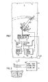
- the Fig. 1 embodiment of apparatus for detecting continuously the presence of cracks in a continuously cast test piece comprises a proximity sensor arrangement which may incorporate one or more proximity sensors mounted in a head placed on one end of an arm 2 of a pivotable or swingable robot 3.
- the head is positioned at a substantially constant, regulated distance from one surface of a forwardly moving, still flowing continuously cast test piece 4.
- the robot 3 is swung from one side of the test piece 4 to the other by drive means intended herefor. It will be understood, however, that a robot 3 may be positioned either beneath or adjacent one side of the test piece, or adjacent all sides thereof, depending on which of the surfaces of the test piece is to be examined for cracks.
- a measuring system which is located above the test piece.
- the sensor head 1 on the arm 2 of the robot can be moved across the test piece 4 in one continuous movement.
- the sensor head is only able to cover a relatively small area of the test piece surface during said examination procedure it is preferable to arrange for the sensor arrangement to move on the sensor head 1, in the execution of a crack detecting sweep cycle, in a direction different to the sweep direction. Accordingly, in the embodiment illustrated in Fig. 1 the head 1 is driven reciprocatingly in the direction of the arrow A.
- the sensor arrangement moves across the test piece along a circular arc with superimposed transverse oscillatory movements.
- the apparatus according to the invention can also be used with great advantage solely for detecting the location of an edge of a test piece, i.e. without requiring the apparatus to detect the presence of cracks.
- the sensor arrangement need not move transversely to the sweep direction.
- the sensor arrangement co-acts with a signal transmitting and signal processing unit 6 which calculates the location of detected cracks in a transverse direction, with a starting point from the last detected position of an edge on one side of the test piece, and in a longitudinal direction with a starting point from the time at which the leading edge of the test piece was last located and also on the basis of the speed at which the test piece is advanced, this data being obtained through a sensor 5 incorpo. rated in the continuous casting apparatus.
- the unit 6 presents this data on a display or presentation unit 7.
- a signal from the unit 6 is applied on a second output immediately a radical change occurs in the value of the measuring signal or signals, such as when no eddy currents are induced in the underlying material of the test piece or when the eddy currents decrease to a marked extent, which either indicates that the sensor arrangement has been moved inwardly or outwardly over the edge of the test piece 4, or that the test piece 4 has located therein a crack of particular width and depth immediately beneath the sensor arrangement.
- This signal is transmitted to an evaluating circuit 8 which may optionally be constructed to carry out a so-called probability check on the signal, by checking the rotational position of the robot arm, this position being indicated by a control circuit 9, which is normally incorporated in the robot but which for the sake of simplicity is shown separately, and which accepts the signal from the unit 6 as an edge marking if said rotational position lies outside pre-determined limits in one direction or the other.
- a control circuit 9 which is normally incorporated in the robot but which for the sake of simplicity is shown separately, and which accepts the signal from the unit 6 as an edge marking if said rotational position lies outside pre-determined limits in one direction or the other.
- the evaluating circuit 8 may be constructed such as to send a signal to an alarm or warning circuit 10 when said circuit 8 receives a signal from the unit 6 with the sensor arrangement located above the test piece 4.
- Fig. 2 illustrates an embodiment of a suitable proximity sensor based on eddy current inducement, this proximity sensor being of the kind illustrated and described in Swedish Patent Application No. 8302738-3.
- a coil 11 is supplied with alternating current from the signal transmitting and signal processing unit 6.
- the alternating current includes two mutually different components fL and fH.
- Eddy currents of corresponding frequency content are induced in the surface of the test piece, through the inductive coupling thereto.
- the voltage across the coil is detected and divided into its respective frequency components.
- the resultant signals are utilized for crack detection purposes.
- One of these signals, namely the signal having the higher frequency is used for edge marking purposes, since this signal has a high so-called lift-off-dependency, i.e. is highly dependent on the distance of the sensor from the measured surface on the test piece.
- Fig. 3 illustrates apparatus for localizing cracks, in which a transducer arrangement is moved across a test piece in a rotational movement pattern.
- the test piece here referenced 12, moves forwards continuously in the direction of the arrow B.
- a sensor arrangement 13 is mounted for rotation on a sensor head 14, which incorporates a drive motor.
- the sensor head 14 is mounted for guided movement along a beam 15, which is placed on pillars 16, 17 and extends across the path travelled by the test piece. It will be understood that when the apparatus is used solely for edge detecting purposes the sensor need not rotate.
- the signal transmitting and signal processing unit 18 feeds auxiliary signals to the sensor arrangement 13, as beforedescribed, and evaluates the signal or signals received from said sensor arrangement.
- the unit 18 is connected in turn to a control and monitoring unit 19.
- the unit 19 incorporates a computer 20 or like device with peripheral equipment for presenting the results obtained, such as a printer 21 and/or an image screen or the like, a key-board 22 for manual insertion of data and/or some other type of data input unit 23.
- the unit 19 is also supplied with a signal from a positional indicating and positional control unit 24 operating in conjunction with the sensor arrangement.
- the unit 24 indicates continuously the position of the sensor arrangement 13 in relation to the test piece, both in the lateral direction (x) and the vertical direction (y), and initiates adjustment of the distance of the sensor arrangement from the opposing surface of the test piece, by actuating a height regulating device (not shown) in a manner to raise and lower the head 14.
- a height regulating device not shown
- the momentary forward speed of the test piece is also measured, with the aid of a sensor 5', and the result of the measurement is delivered to the computer 20, which calculates the distance through which the test piece has moved, on the basis of said speed.
- the unit 19 also controls the movement of the head 14 along the beam 15, in the manner illustrated in Fig. 4.
- This control procedure is also suitable for the embodiment illustrated in Fig. 1.
- the two vertical broken lines K 1 and K 2 represent the probable positions of the two edges of the test piece. These positions are calculated by the computer 20 and the mean value of the position of a detected edge during a given number (e.g. 10) of previously effected edge detecting procedures. It will be understood, however, that it is possible to use solely the latest detected positions, although the procedure in which a mean value is taken of a plurality of edge detections is to be preferred.
- the sensor head 14 begins its journey across the test piece with at least a small part of the path travelled by the sensor arrangement located externally of the edge K 1 .
- the sensor head is aooelerated from a zero speed at 8 1 to the intended speed of travel, reached at S 2 , and maintains this intended speed until reaching the point referenced S 31 which lies at a distance from the edge K 2 such that the head 14 is able to decelerate to a far lower speed than the travelling speed reached at S 4 , which lies slightly inwardly of the edge K 2 , and is maintained at this lower speed until the edge K 2 is detected at S 51 whereafter the head is decelerated to zero speed at S 6*
- the head 14 is then held stationary at S 6 until the test piece has advanced through a pre-determined distance from, and including the moment at which the head 14 is caused to move over the test piece at S 1
- the head 14 is then caused to move in the opposite direction across the test piece in a corresponding speed pattern S' 1 -S' 6
- the reason for decelerating the speed of the sensor head to the lowest speed at S 4 and S' 4 respectively is because the sensor arrangement 13 shall pass slowly over respective edges, thereby enabling the location of said edges to be determined in a particularly precise manner.
- the computer computes the edge signals from the signals obtained from the units 18 and 24 and, with a starting point from at least one of the edge signals, optionally also the position and extension of the detected cracks, using herefor the edge marking obtained at one edge.
- the width of the test piece is calculated with the aid of the edge signal obtained from the other edge.
- at least two memory regions are reserved in the computer 20 for width calculation purposes. In this way, the width of the test piece is calculated continuously, and the results may be presented on a display or presentation unit 21.
- the unit 21 may optionally also incorporate a curve printer having two channels for visible display.
- the edge signals obtained as the sensor arrangement passes locations S 5 and S' 5 can be utilized for generating a stop signal effective for stopping movement of the head 14 along the beam 15.
- Fig. 5 illustrates an example of the pattern of movement executed by the sensor arrangement 13 when the head 14 is passed backwards and forwards across the test piece a number of times on the beam 15.
- the span capable of being covered by the actual sensor itself is solely equal to the breadth of the illustrated helically shaped, hatched band, although by rotating the sensor there is obtained with each pass over the test piece a covering band equal in width to the diameter of the circle described by said rotation. It will be understood that the loops or turns of the helix may lie closer together than those illustrated.
- the velocity diagram in Fig. 4 shall, in this case, be read so that the velocity in this close proximity of a relevant edge denotes the velocity of the outer part of the sensor head at said edge. This has been indicated in Fig. 5, by marking therein the edges K 1 and K 2 and the positions for S 1 , S 51 S t 1 and S' S .
- the indication of the position of an edge of the test piece, carried out during each scanning cycle, need not necessarily be effected with the same sensor as that used for crack.detection, but that, for example, a non-rotating sensor 27 may be mounted on the outside of the head 14. In this arrangement, the rotating sensor will pass beyond the test piece through a distance equivalent to one radius of rotation prior to the non-rotating sensor 27 indicating the location of said edge. If wishing to reduce the stationary edge time to the greatest possible extent when reaching the edge, the actual head 14 itself may also be arranged to rotate through at least one half revolution, and to be rotated so as to turn the non-rotatable sensor 27 towards the opposite edge prior to travel in the opposite direction.
Landscapes
- Physics & Mathematics (AREA)
- General Physics & Mathematics (AREA)
- Chemical & Material Sciences (AREA)
- Chemical Kinetics & Catalysis (AREA)
- Electrochemistry (AREA)
- Health & Medical Sciences (AREA)
- Life Sciences & Earth Sciences (AREA)
- Analytical Chemistry (AREA)
- Biochemistry (AREA)
- General Health & Medical Sciences (AREA)
- Immunology (AREA)
- Pathology (AREA)
- Investigating Or Analyzing Materials By The Use Of Magnetic Means (AREA)
- Measurement Of Length, Angles, Or The Like Using Electric Or Magnetic Means (AREA)
Applications Claiming Priority (2)
| Application Number | Priority Date | Filing Date | Title |
|---|---|---|---|
| SE8504913A SE456533B (sv) | 1985-10-18 | 1985-10-18 | Forfarande och anordning for kantdetektering av provobjekt i en met- och/eller kontrollanordning |
| SE8504913 | 1985-10-18 |
Publications (2)
| Publication Number | Publication Date |
|---|---|
| EP0220144A1 true EP0220144A1 (fr) | 1987-04-29 |
| EP0220144B1 EP0220144B1 (fr) | 1991-01-09 |
Family
ID=20361835
Family Applications (1)
| Application Number | Title | Priority Date | Filing Date |
|---|---|---|---|
| EP86850333A Expired - Lifetime EP0220144B1 (fr) | 1985-10-18 | 1986-10-03 | Procédé et dispositif pour détecter le bord d'une pièce |
Country Status (5)
| Country | Link |
|---|---|
| US (1) | US4816760A (fr) |
| EP (1) | EP0220144B1 (fr) |
| JP (1) | JPS6295458A (fr) |
| DE (1) | DE3676785D1 (fr) |
| SE (1) | SE456533B (fr) |
Cited By (1)
| Publication number | Priority date | Publication date | Assignee | Title |
|---|---|---|---|---|
| EP4270573A3 (fr) * | 2022-04-28 | 2024-08-07 | Volkswagen Ag | Procédé et dispositif de détection d'un bord lors de la fabrication d'une pile de cellules |
Families Citing this family (4)
| Publication number | Priority date | Publication date | Assignee | Title |
|---|---|---|---|---|
| US5617856A (en) * | 1993-09-24 | 1997-04-08 | Osaka Gas Company Limited | Biological information-measuring apparatus |
| JP3866935B2 (ja) * | 2001-06-08 | 2007-01-10 | ジーイー・メディカル・システムズ・グローバル・テクノロジー・カンパニー・エルエルシー | 磁気共鳴撮影装置 |
| JP2006349627A (ja) * | 2005-06-20 | 2006-12-28 | Yokohama Rubber Co Ltd:The | ワイヤ位置検出方法及びその装置 |
| JP5146673B2 (ja) * | 2008-08-19 | 2013-02-20 | 住友金属鉱山シポレックス株式会社 | Alcパネルの主筋かぶり厚検査方法 |
Citations (3)
| Publication number | Priority date | Publication date | Assignee | Title |
|---|---|---|---|---|
| US3311820A (en) * | 1963-06-07 | 1967-03-28 | Mckay Machine Co | Actuating circuit for automatically reversing a reciprocal scanner |
| US3311819A (en) * | 1963-06-03 | 1967-03-28 | Mckay Machine Co | Automatic billet scanning apparatus with edge sensing means for reversing scan |
| EP0101914A2 (fr) * | 1982-08-14 | 1984-03-07 | Institut Dr. Friedrich Förster Prüfgerätebau GmbH & Co. KG | Méthode et dispositif de balayage de la surface d'un objet |
Family Cites Families (2)
| Publication number | Priority date | Publication date | Assignee | Title |
|---|---|---|---|---|
| JPS5151963A (en) * | 1974-10-31 | 1976-05-07 | Nippon Kokan Kk | Kinzokuobijotaino jihakeijosokuteihoho oyobi sochi |
| SE8302738L (sv) * | 1983-05-16 | 1984-11-17 | Bengt Hjalmar Tornblom | Anordning och/eller sett baserad pa frekvensvalsprincip |
-
1985
- 1985-10-18 SE SE8504913A patent/SE456533B/sv not_active IP Right Cessation
-
1986
- 1986-10-03 EP EP86850333A patent/EP0220144B1/fr not_active Expired - Lifetime
- 1986-10-03 DE DE8686850333T patent/DE3676785D1/de not_active Expired - Fee Related
- 1986-10-08 US US06/917,075 patent/US4816760A/en not_active Expired - Fee Related
- 1986-10-16 JP JP61246456A patent/JPS6295458A/ja active Pending
Patent Citations (3)
| Publication number | Priority date | Publication date | Assignee | Title |
|---|---|---|---|---|
| US3311819A (en) * | 1963-06-03 | 1967-03-28 | Mckay Machine Co | Automatic billet scanning apparatus with edge sensing means for reversing scan |
| US3311820A (en) * | 1963-06-07 | 1967-03-28 | Mckay Machine Co | Actuating circuit for automatically reversing a reciprocal scanner |
| EP0101914A2 (fr) * | 1982-08-14 | 1984-03-07 | Institut Dr. Friedrich Förster Prüfgerätebau GmbH & Co. KG | Méthode et dispositif de balayage de la surface d'un objet |
Cited By (1)
| Publication number | Priority date | Publication date | Assignee | Title |
|---|---|---|---|---|
| EP4270573A3 (fr) * | 2022-04-28 | 2024-08-07 | Volkswagen Ag | Procédé et dispositif de détection d'un bord lors de la fabrication d'une pile de cellules |
Also Published As
| Publication number | Publication date |
|---|---|
| EP0220144B1 (fr) | 1991-01-09 |
| SE8504913L (sv) | 1987-04-19 |
| DE3676785D1 (de) | 1991-02-14 |
| SE8504913D0 (sv) | 1985-10-18 |
| US4816760A (en) | 1989-03-28 |
| JPS6295458A (ja) | 1987-05-01 |
| SE456533B (sv) | 1988-10-10 |
Similar Documents
| Publication | Publication Date | Title |
|---|---|---|
| US4761610A (en) | Apparatus for determining the position of surface defects of a test objects with respect to an edge thereof | |
| US5096044A (en) | Method and apparatus for monitoring the run of a belt | |
| EP0075399B1 (fr) | Détermination d'un référence géographique pour un véhicule en mouvement dans une conduite de tube | |
| KR101792573B1 (ko) | 식품 내 금속 검출 방법 및 장치 | |
| US6105347A (en) | Device and method for locating and removing foreign bodies in agricultural machinery | |
| JP2003233423A (ja) | 自立走行車の衝突防止方法および装置 | |
| US4816760A (en) | Method and apparatus for detecting the position of an edge of a test piece | |
| EP0272077A2 (fr) | Dispositif d'affichage d'un cours | |
| EP0509809A2 (fr) | Appareil d'indication de l'usure d'un rouleau d'écrasement et méthode | |
| EP0019604B2 (fr) | Méthode et appareil pour détecter des discontinuités dans des matériaux | |
| JPH06109862A (ja) | 埋設管に於ける対象個所の検知方法 | |
| US4805019A (en) | Non-contact apparatus and method for measuring the length of aluminum sheet and plate | |
| JP2002108452A (ja) | 無人搬送車の走行制御装置 | |
| JP5312221B2 (ja) | メタルタッチ検出装置及びメタルタッチ検出方法 | |
| KR20010063525A (ko) | 냉연강판용 폭측정장치 | |
| JP3473404B2 (ja) | 溶接ビード中心位置検出器 | |
| EP0108845B1 (fr) | Dispositif de mesure | |
| JPS61253117A (ja) | 金属ストリツプコイルの尾端検出装置 | |
| JPH08285464A (ja) | 溶融金属容器耐火壁中の地金検知方法及び装置 | |
| JP3110241B2 (ja) | ロール疵の検出方法 | |
| JPH05329523A (ja) | 縦型ルーパキャリッジの傾斜測定方法 | |
| JPH0886606A (ja) | 水中マーク認識装置 | |
| JP2025163336A (ja) | 地中レーダ装置及びその埋設物探査方法 | |
| KR200188752Y1 (ko) | 롤 연삭기의 실시간 비접촉식 롤형상 측정장치 | |
| GB2618833A (en) | Metal oxidation determining apparatus |
Legal Events
| Date | Code | Title | Description |
|---|---|---|---|
| PUAI | Public reference made under article 153(3) epc to a published international application that has entered the european phase |
Free format text: ORIGINAL CODE: 0009012 |
|
| AK | Designated contracting states |
Kind code of ref document: A1 Designated state(s): DE FR GB |
|
| 17P | Request for examination filed |
Effective date: 19870928 |
|
| 17Q | First examination report despatched |
Effective date: 19891106 |
|
| GRAA | (expected) grant |
Free format text: ORIGINAL CODE: 0009210 |
|
| AK | Designated contracting states |
Kind code of ref document: B1 Designated state(s): DE FR GB |
|
| REF | Corresponds to: |
Ref document number: 3676785 Country of ref document: DE Date of ref document: 19910214 |
|
| ET | Fr: translation filed | ||
| PLBE | No opposition filed within time limit |
Free format text: ORIGINAL CODE: 0009261 |
|
| STAA | Information on the status of an ep patent application or granted ep patent |
Free format text: STATUS: NO OPPOSITION FILED WITHIN TIME LIMIT |
|
| 26N | No opposition filed | ||
| PGFP | Annual fee paid to national office [announced via postgrant information from national office to epo] |
Ref country code: GB Payment date: 19930923 Year of fee payment: 8 |
|
| PGFP | Annual fee paid to national office [announced via postgrant information from national office to epo] |
Ref country code: FR Payment date: 19931011 Year of fee payment: 8 Ref country code: DE Payment date: 19931011 Year of fee payment: 8 |
|
| PG25 | Lapsed in a contracting state [announced via postgrant information from national office to epo] |
Ref country code: GB Effective date: 19941003 |
|
| GBPC | Gb: european patent ceased through non-payment of renewal fee |
Effective date: 19941003 |
|
| PG25 | Lapsed in a contracting state [announced via postgrant information from national office to epo] |
Ref country code: FR Effective date: 19950630 |
|
| PG25 | Lapsed in a contracting state [announced via postgrant information from national office to epo] |
Ref country code: DE Effective date: 19950701 |
|
| REG | Reference to a national code |
Ref country code: FR Ref legal event code: ST |