EP0220725A2 - Spritzgiessform für eine optische Platte - Google Patents
Spritzgiessform für eine optische Platte Download PDFInfo
- Publication number
- EP0220725A2 EP0220725A2 EP86115023A EP86115023A EP0220725A2 EP 0220725 A2 EP0220725 A2 EP 0220725A2 EP 86115023 A EP86115023 A EP 86115023A EP 86115023 A EP86115023 A EP 86115023A EP 0220725 A2 EP0220725 A2 EP 0220725A2
- Authority
- EP
- European Patent Office
- Prior art keywords
- mold
- sliding member
- stamper
- injection mold
- injection
- Prior art date
- Legal status (The legal status is an assumption and is not a legal conclusion. Google has not performed a legal analysis and makes no representation as to the accuracy of the status listed.)
- Granted
Links
Images

Classifications
-
- B—PERFORMING OPERATIONS; TRANSPORTING
- B29—WORKING OF PLASTICS; WORKING OF SUBSTANCES IN A PLASTIC STATE IN GENERAL
- B29C—SHAPING OR JOINING OF PLASTICS; SHAPING OF MATERIAL IN A PLASTIC STATE, NOT OTHERWISE PROVIDED FOR; AFTER-TREATMENT OF THE SHAPED PRODUCTS, e.g. REPAIRING
- B29C45/00—Injection moulding, i.e. forcing the required volume of moulding material through a nozzle into a closed mould; Apparatus therefor
- B29C45/17—Component parts, details or accessories; Auxiliary operations
- B29C45/26—Moulds
- B29C45/263—Moulds with mould wall parts provided with fine grooves or impressions, e.g. for record discs
-
- B—PERFORMING OPERATIONS; TRANSPORTING
- B29—WORKING OF PLASTICS; WORKING OF SUBSTANCES IN A PLASTIC STATE IN GENERAL
- B29C—SHAPING OR JOINING OF PLASTICS; SHAPING OF MATERIAL IN A PLASTIC STATE, NOT OTHERWISE PROVIDED FOR; AFTER-TREATMENT OF THE SHAPED PRODUCTS, e.g. REPAIRING
- B29C45/00—Injection moulding, i.e. forcing the required volume of moulding material through a nozzle into a closed mould; Apparatus therefor
- B29C45/17—Component parts, details or accessories; Auxiliary operations
- B29C45/26—Moulds
- B29C45/2608—Mould seals
-
- B—PERFORMING OPERATIONS; TRANSPORTING
- B29—WORKING OF PLASTICS; WORKING OF SUBSTANCES IN A PLASTIC STATE IN GENERAL
- B29C—SHAPING OR JOINING OF PLASTICS; SHAPING OF MATERIAL IN A PLASTIC STATE, NOT OTHERWISE PROVIDED FOR; AFTER-TREATMENT OF THE SHAPED PRODUCTS, e.g. REPAIRING
- B29C45/00—Injection moulding, i.e. forcing the required volume of moulding material through a nozzle into a closed mould; Apparatus therefor
- B29C45/17—Component parts, details or accessories; Auxiliary operations
- B29C45/26—Moulds
- B29C45/263—Moulds with mould wall parts provided with fine grooves or impressions, e.g. for record discs
- B29C2045/2648—Outer peripheral ring constructions
-
- B—PERFORMING OPERATIONS; TRANSPORTING
- B29—WORKING OF PLASTICS; WORKING OF SUBSTANCES IN A PLASTIC STATE IN GENERAL
- B29C—SHAPING OR JOINING OF PLASTICS; SHAPING OF MATERIAL IN A PLASTIC STATE, NOT OTHERWISE PROVIDED FOR; AFTER-TREATMENT OF THE SHAPED PRODUCTS, e.g. REPAIRING
- B29C45/00—Injection moulding, i.e. forcing the required volume of moulding material through a nozzle into a closed mould; Apparatus therefor
- B29C45/17—Component parts, details or accessories; Auxiliary operations
- B29C45/26—Moulds
- B29C45/263—Moulds with mould wall parts provided with fine grooves or impressions, e.g. for record discs
- B29C2045/2657—Drive means for the outer peripheral ring
-
- B—PERFORMING OPERATIONS; TRANSPORTING
- B29—WORKING OF PLASTICS; WORKING OF SUBSTANCES IN A PLASTIC STATE IN GENERAL
- B29C—SHAPING OR JOINING OF PLASTICS; SHAPING OF MATERIAL IN A PLASTIC STATE, NOT OTHERWISE PROVIDED FOR; AFTER-TREATMENT OF THE SHAPED PRODUCTS, e.g. REPAIRING
- B29C45/00—Injection moulding, i.e. forcing the required volume of moulding material through a nozzle into a closed mould; Apparatus therefor
- B29C45/0025—Preventing defects on the moulded article, e.g. weld lines, shrinkage marks
-
- Y—GENERAL TAGGING OF NEW TECHNOLOGICAL DEVELOPMENTS; GENERAL TAGGING OF CROSS-SECTIONAL TECHNOLOGIES SPANNING OVER SEVERAL SECTIONS OF THE IPC; TECHNICAL SUBJECTS COVERED BY FORMER USPC CROSS-REFERENCE ART COLLECTIONS [XRACs] AND DIGESTS
- Y10—TECHNICAL SUBJECTS COVERED BY FORMER USPC
- Y10S—TECHNICAL SUBJECTS COVERED BY FORMER USPC CROSS-REFERENCE ART COLLECTIONS [XRACs] AND DIGESTS
- Y10S425/00—Plastic article or earthenware shaping or treating: apparatus
- Y10S425/808—Lens mold
-
- Y—GENERAL TAGGING OF NEW TECHNOLOGICAL DEVELOPMENTS; GENERAL TAGGING OF CROSS-SECTIONAL TECHNOLOGIES SPANNING OVER SEVERAL SECTIONS OF THE IPC; TECHNICAL SUBJECTS COVERED BY FORMER USPC CROSS-REFERENCE ART COLLECTIONS [XRACs] AND DIGESTS
- Y10—TECHNICAL SUBJECTS COVERED BY FORMER USPC
- Y10S—TECHNICAL SUBJECTS COVERED BY FORMER USPC CROSS-REFERENCE ART COLLECTIONS [XRACs] AND DIGESTS
- Y10S425/00—Plastic article or earthenware shaping or treating: apparatus
- Y10S425/812—Venting
Definitions
- the present invention relates to an injection mold for injection molding substrates for high-density recording media, such as ROM disks as CD's and VD's, or E-DRAW disks.
- plastic materials are preferable in respect of weight, strength and productivity.
- the plastic substrate for the optical disk is very thin and flat having a thickness in the range of 1.2 to 1.5mm and a diameter of approximately 300mm at the maximum and a plastic material, such as an acrylic resin or a polycarbonate resin, having low fluidity is used as material, it has been difficult to form a satisfactory plastic substrate through injection molding up to the present.
- the capability of reproducing the surface shape of a stamper placed within the mold is the most important property. Generally, the condition of reproduction of the surface shape of the stamper on the substrate is dependent on the injection pressure.
- the higher the injection pressure the better the submicroscopic surface pattern of the stamper for a high-density information recording medium is transferred to the substrate.
- high injection pressure is necessary to improve the transference of the minute surface shape in the peripheral portion of the stamper in a thin and flat cavity.
- a disk molding machine capable of applying a small clamping pressure is employed for molding the disk in spite of the cavity having a large area extending perpendicularly to the direction of the clamping pressure.
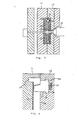
- the conventional injection mold for injection-molding a plastic substrate for the optical disk has a construction as illustrated in Figs. 1 or 2.
- a mold has a molding cavity 3 defined by the inner surfaces of a pair of half molds, for example, a movable half mold 1 and a fixed half mold 2.
- a stamper 4 having submicron order information pits or information tracks is secured to part of the surface of the molding cavity with a stamper holding ring 5.
- a ring 6 (for holding another stamper, not shown) is attached opposite to the stamper holding ring 5 to the surface of the molding cavity of the fixed half mold.
- the mold having a construction as shown in Fig. 1 is opened when a high injection pressure is applied thereto, the molten resin flows into the gap between the rings 5 and 6 to form burrs or flushes.
- the burrs require disadvantageously additional burring work and makes the molding cavity dirty, which is a significant problem in manufacturing the optical disk which requires the utmost cleanliness of the molding cavity.
- FIG. 2 Another conventional injection mold is shown in Fig. 2, in which members corresponding to those shown in Fig. 1 are designated by the same reference numerals with a prime.
- the injection mold of Fig. 2 is not provided with the ring 6.
- the circumference 9 of a projection formed in the fixed half mold 2' is placed in abutment with the tapered inner circumference of a stamper holding ring 5' to define a molding cavity.
- This construction does not have the problem of burrs with which the construction shown in Fig. 1 is troubled.
- the annular sliding member featuring the present invention is disposed in the vicinity of the outer circumference of the molding cavity so as to constitute a part of the mold assembly defining the outer circumference of the molding cavity.
- the sliding member may be held axially slidably in an annular groove formed in a portion of one of the two half molds.
- the axial sliding tranvel of the sliding member may correspond to the length of a gap formed between the half molds when an injection pressure is applied to the injection mold, namely, a value in the range of 0.05 to 0.2mm.
- the biasing means for axially biasing the sliding member may be well-known biasing means, for example, elastic members such as coil springs, leaf springs or rubber blocks, or a hydraulic circuit.
- the biasing means apply a force to the sliding member to axially bias the sliding member toward the bottom surface of the molding cavity of the other half mold.
- the biasing force must be smaller than the mold clamping force and, at the same time, must be greater than the sum of a force produced by the resin injected into the molding cavity, the frictional resistance of the resin that works on the sliding member, and the frictional resistances of other parts contiguous to the sliding member that / work on the sliding member.
- the bottom surface of the molding cavity may be the inner surface of the injection mold
- a stamper is placed on the bottom surface of the molding cavity and is held in place by a well-known stamper holder.
- the outer end surface of the sliding member must be brought into abutment with the surface of the stamper when the injection mold is closed.
- Fig. 3 is a schematic sectional view of an injection mold incorporating the present invention, for injection-molding a plastic substrate for an optical disk.
- a molten resin is injected from an injection nozzle 21 through a sprue into a molding cavity 20 formed between a pair of half molds 10 and 11 to fill up the molding cavity 20.
- a stamper 12 is placed on one of the bottom surfaces of the molding cavity 20 in the half mold 11. The stamper 12 is held firmly in place with an inner stamper holding ring 16 and an outer stamper holding ring 13.
- a sliding member 14 is placed in the-vicinity of the outer circumference of the half mold 10 not provided with any stamper.
- the sliding member 14 is biased axially toward the inner surface of the half mold 11 by coil springs 15.
- the sliding member 14 is fitted in an annular groove 17 formed in the half mold 10.
- Flanges 18 formed at the rear end of the sliding member 14 are received in an annular groove 19 having an outer diameter greater than that of the annular groove 17 and an inner diameter smaller than that of the annular groove 17 so that the sliding member 14 will not fall off the half mold 10 when the injection mold is opened.
- the half molds 10 and 11 are parted slightly from each other to form a gap in the range of 0.05 to 0,2mm, while the sliding member 14 is moved axially relative to the half mold 10 in a direction opposite the direction of movement of the half mold 10 by the coil springs 15, and hence the sliding member 14 is always in contact with the stamper holding ring 13. Consequently, the size of the clear- . ance between the outer'circumference of the sliding member 14 and the inner circumference of the stamper holding ring 13 is invariable. Accordingly, it is possible to optionally design the clearance between the outer circumference of the sliding member 14 and the inner circumference of the stamper holding ring 13 to provide a gas vent.
- the clearance since an optional design of the clearance is possible, it is not necessary to adjust the clearance to provide a gas vent by adjusting the stamper holding ring fastening force. Accordingly, an optimum weak fastening force is applied to the stamper, and thereby the life of the stamper is enhanced greatly. Still further, since the sliding member 14 restricts the flow of the resin, burrs or flashes will not be formed and the outer circumference of the sliding member 14 and the inner circumference of the stamper holding ring 13 may be finishied with a low machining accuracy, so that seizure between the sliding member 14 and the stamper holding ring 13 will not occur.
- the embodiment described hereinbefore employs a plurality of the coil springs 15, for example, eight coil springs 15, arranged at regular angular intervals along the circumference of the sliding member 14, it is more desirable to employ a hydraulic mechanism to apply a pressure more uniformly to the sliding member 14.
Landscapes
- Engineering & Computer Science (AREA)
- Manufacturing & Machinery (AREA)
- Mechanical Engineering (AREA)
- Moulds For Moulding Plastics Or The Like (AREA)
Applications Claiming Priority (2)
| Application Number | Priority Date | Filing Date | Title |
|---|---|---|---|
| JP60245678A JPS62105616A (ja) | 1985-11-01 | 1985-11-01 | 光デイスクの射出成形用金型 |
| JP245678/85 | 1985-11-01 |
Publications (3)
| Publication Number | Publication Date |
|---|---|
| EP0220725A2 true EP0220725A2 (de) | 1987-05-06 |
| EP0220725A3 EP0220725A3 (en) | 1989-01-25 |
| EP0220725B1 EP0220725B1 (de) | 1992-08-05 |
Family
ID=17137182
Family Applications (1)
| Application Number | Title | Priority Date | Filing Date |
|---|---|---|---|
| EP86115023A Expired EP0220725B1 (de) | 1985-11-01 | 1986-10-29 | Spritzgiessform für eine optische Platte |
Country Status (4)
| Country | Link |
|---|---|
| US (1) | US4741689A (de) |
| EP (1) | EP0220725B1 (de) |
| JP (1) | JPS62105616A (de) |
| DE (1) | DE3686306T2 (de) |
Cited By (4)
| Publication number | Priority date | Publication date | Assignee | Title |
|---|---|---|---|---|
| FR2607369A1 (fr) * | 1986-11-27 | 1988-06-03 | Kloeckner Ferromatik Desma | Forme pour tiges de chaussures pour le surmoulage de semelles |
| EP0803339A1 (de) * | 1996-04-26 | 1997-10-29 | Sony Corporation | Giessvorrichtung und -verfahren für optische Platten |
| NL1012111C2 (nl) * | 1999-05-20 | 2000-11-23 | Axxicon Moulds Eindhoven Bv | Spuitgietmatrijssamenstel. |
| NL1017287C2 (nl) * | 2001-02-06 | 2002-08-07 | Otb Group Bv | Werkwijze en inrichting voor het spuitgieten van een kunststof voorwerp. |
Families Citing this family (17)
| Publication number | Priority date | Publication date | Assignee | Title |
|---|---|---|---|---|
| JPS63130320A (ja) * | 1986-11-20 | 1988-06-02 | Meiki Co Ltd | デイスク成形金型 |
| JP2642158B2 (ja) * | 1988-08-16 | 1997-08-20 | 住友重機械工業株式会社 | 光ディスク基板成形用金型 |
| US5180595A (en) * | 1989-03-31 | 1993-01-19 | Hitachi Maxell, Ltd. | Metal mold for resin substrate for an optical recording medium |
| JPH0460417U (de) * | 1990-09-28 | 1992-05-25 | ||
| US5427520A (en) * | 1992-01-31 | 1995-06-27 | Sony Corporation | Mold device for fabricating disc substrate |
| KR100755089B1 (ko) | 1999-02-12 | 2007-09-03 | 제너럴 일렉트릭 캄파니 | 저장 매체, 기판 제조 방법, 데이터 검색 방법, 엠보싱 방법 및 데이터 저장 매체 형성 방법 |
| US7179551B2 (en) | 1999-02-12 | 2007-02-20 | General Electric Company | Poly(arylene ether) data storage media |
| US6372175B1 (en) | 1999-09-17 | 2002-04-16 | General Electric Company | Resin pellets for injection molding |
| JP2002240101A (ja) * | 2000-12-15 | 2002-08-28 | Sony Corp | ディスク基板及びそれを射出成形する金型装置とディスク基板取出し用ロボット |
| US20020155216A1 (en) * | 2001-04-19 | 2002-10-24 | Reitz John Bradford | Spin coated media |
| TWI232156B (en) * | 2003-06-25 | 2005-05-11 | Coretronic Corp | Method for forming microstructure optical elements |
| US7906194B2 (en) * | 2005-03-31 | 2011-03-15 | Cinram International Inc. | Optical disc with textured edge |
| US20090074904A1 (en) * | 2005-05-19 | 2009-03-19 | Yoshiyuki Goto | Mold for forming disc, method for manufacture same, and mold parts |
| EP2465659A1 (de) * | 2010-12-20 | 2012-06-20 | Axxicon Moulds Eindhoven B.V. | Stempelanordnung, Einspritzdruckgussvorrichtung und Verfahren zur Herstellung von optischen Datenträgern |
| JP6700702B2 (ja) * | 2015-09-30 | 2020-05-27 | キヤノン株式会社 | 射出成形金型、成形品の製造方法、ドーム型カバーの製造方法、及び金型部品 |
| ES2681168B1 (es) * | 2017-03-10 | 2019-06-21 | Comercial De Utiles Y Moldes Sa | Dispositivo para desmoldar negativos en moldes de inyección de termoplástico |
| JP6985187B2 (ja) * | 2018-03-15 | 2021-12-22 | トヨタ自動車株式会社 | 樹脂体の金型 |
Family Cites Families (13)
| Publication number | Priority date | Publication date | Assignee | Title |
|---|---|---|---|---|
| US1029488A (en) * | 1910-12-14 | 1912-06-11 | John E Burghoff | Comb embossing and cutting dies. |
| US2998622A (en) * | 1957-12-23 | 1961-09-05 | Applic Ind Plastiques Soc D | Apparatus for pressing gramophone records |
| DE2435272A1 (de) * | 1974-07-23 | 1976-02-05 | Westfaelische Metall Industrie | Absperrvorrichtung fuer den entlueftungskanal einer giessform |
| US3989436A (en) * | 1975-12-18 | 1976-11-02 | Rca Corporation | Apparatus for producing injection molded and centrally apertured disc records |
| US4118168A (en) * | 1977-05-02 | 1978-10-03 | Husky Injection Molding Systems Limited | Guidance system for shallow articles discharged from a mold cavity |
| GB1603844A (en) * | 1977-08-24 | 1981-12-02 | British Industrial Plastics | Injection moulding machines |
| JPS5953858B2 (ja) * | 1978-05-13 | 1984-12-27 | ダイセル化学工業株式会社 | 度付レンズの成形方法 |
| NL7906117A (nl) * | 1979-08-10 | 1981-02-12 | Philips Nv | Werkwijze en inrichting voor het vervaardigen van een kunststofinformatiedrager. |
| US4372741A (en) * | 1980-10-31 | 1983-02-08 | Discovision Associates | Hot sprue valve assembly for an injection molding machine |
| FR2516286A1 (fr) * | 1981-11-06 | 1983-05-13 | Thomson Csf | Procede d'obtention d'un disque-copie a partir d'une gravure originale portee par une matrice |
| JPS5945497A (ja) * | 1982-09-08 | 1984-03-14 | 三菱電機株式会社 | 電子音発生装置 |
| JPS59153213U (ja) * | 1983-03-31 | 1984-10-15 | 株式会社吉野工業所 | 射出成形用金型装置 |
| DE3817500C1 (de) * | 1988-05-21 | 1989-10-05 | Rohde & Schwarz Gmbh & Co Kg, 8000 Muenchen, De |
-
1985
- 1985-11-01 JP JP60245678A patent/JPS62105616A/ja active Granted
-
1986
- 1986-10-29 DE DE8686115023T patent/DE3686306T2/de not_active Expired - Lifetime
- 1986-10-29 EP EP86115023A patent/EP0220725B1/de not_active Expired
- 1986-10-30 US US06/924,662 patent/US4741689A/en not_active Expired - Fee Related
Cited By (6)
| Publication number | Priority date | Publication date | Assignee | Title |
|---|---|---|---|---|
| FR2607369A1 (fr) * | 1986-11-27 | 1988-06-03 | Kloeckner Ferromatik Desma | Forme pour tiges de chaussures pour le surmoulage de semelles |
| EP0803339A1 (de) * | 1996-04-26 | 1997-10-29 | Sony Corporation | Giessvorrichtung und -verfahren für optische Platten |
| US5852329A (en) * | 1996-04-26 | 1998-12-22 | Sony Corporation | Optical disc molding device and molding method for optical disc |
| NL1012111C2 (nl) * | 1999-05-20 | 2000-11-23 | Axxicon Moulds Eindhoven Bv | Spuitgietmatrijssamenstel. |
| NL1017287C2 (nl) * | 2001-02-06 | 2002-08-07 | Otb Group Bv | Werkwijze en inrichting voor het spuitgieten van een kunststof voorwerp. |
| WO2002062554A1 (en) * | 2001-02-06 | 2002-08-15 | O.T.B. Group B.V. | Method and installation for injection moulding a plastic article |
Also Published As
| Publication number | Publication date |
|---|---|
| EP0220725A3 (en) | 1989-01-25 |
| DE3686306T2 (de) | 1992-12-17 |
| US4741689A (en) | 1988-05-03 |
| JPS62105616A (ja) | 1987-05-16 |
| DE3686306D1 (de) | 1992-09-10 |
| EP0220725B1 (de) | 1992-08-05 |
| JPH0586328B2 (de) | 1993-12-10 |
Similar Documents
| Publication | Publication Date | Title |
|---|---|---|
| EP0220725B1 (de) | Spritzgiessform für eine optische Platte | |
| KR0136374B1 (ko) | 광디스크기판의 생산에 사용하는 사출성형 다이장치 | |
| US5427520A (en) | Mold device for fabricating disc substrate | |
| EP0355589A2 (de) | Giessform zum Giessen der Grundlage einer optischen Platte | |
| US7114947B2 (en) | Optical disk mold tooling for reduced edge wedge | |
| US6464487B2 (en) | Injection-moulding tool for the production of information carriers in disc form | |
| JP2707501B2 (ja) | 射出成形用スタンパー | |
| JPH09295319A (ja) | ディスク基板の成形用金型 | |
| JPH02134219A (ja) | 情報記録媒体用基板の成形金型 | |
| JP4093686B2 (ja) | ディスク基板の成形金型及び成形装置 | |
| JP3558530B2 (ja) | 情報記録用基板の成形方法及び成形型 | |
| JPH06134821A (ja) | ディスク用射出成形金型 | |
| JP3631539B2 (ja) | ディスク成形金型 | |
| JPH0751300B2 (ja) | プリフォーマット入り光ディスク基板の成形方法およびそれに用いる金型 | |
| JPS633799Y2 (de) | ||
| JP2000218657A (ja) | 情報記録ディスク基板成形用金型及びそれより得られた基板 | |
| JP2003048234A (ja) | 光ディスク成形金型及び成形基板並びに光ディスク | |
| JPH01264816A (ja) | フォーマット入り光ディスク基板の成形方法 | |
| JP2000293891A (ja) | 光ディスク基板及び光ディスク基板の成形金型 | |
| JP4046881B2 (ja) | 光ディスク及びその製造方法 | |
| JPH11265527A5 (de) | ||
| JPH07192311A (ja) | 光ディスク用基板及びこの光ディスク用基板の成形用金型 | |
| JP2002192576A (ja) | 光ディスク成形用金型装置およびその調整方法 | |
| JPH01264820A (ja) | フォーマット入り光ディスク基板成形用金型 | |
| JPH0729343B2 (ja) | 円盤状記録媒体成形金型 |
Legal Events
| Date | Code | Title | Description |
|---|---|---|---|
| PUAI | Public reference made under article 153(3) epc to a published international application that has entered the european phase |
Free format text: ORIGINAL CODE: 0009012 |
|
| AK | Designated contracting states |
Kind code of ref document: A2 Designated state(s): DE FR GB NL |
|
| PUAL | Search report despatched |
Free format text: ORIGINAL CODE: 0009013 |
|
| AK | Designated contracting states |
Kind code of ref document: A3 Designated state(s): DE FR GB NL |
|
| 17P | Request for examination filed |
Effective date: 19890628 |
|
| 17Q | First examination report despatched |
Effective date: 19900824 |
|
| GRAA | (expected) grant |
Free format text: ORIGINAL CODE: 0009210 |
|
| AK | Designated contracting states |
Kind code of ref document: B1 Designated state(s): DE FR GB NL |
|
| ET | Fr: translation filed | ||
| REF | Corresponds to: |
Ref document number: 3686306 Country of ref document: DE Date of ref document: 19920910 |
|
| PLBI | Opposition filed |
Free format text: ORIGINAL CODE: 0009260 |
|
| 26 | Opposition filed |
Opponent name: GPT AXXICON B.V. Effective date: 19930429 |
|
| NLR1 | Nl: opposition has been filed with the epo |
Opponent name: GPT AXXICON B.V. |
|
| PGFP | Annual fee paid to national office [announced via postgrant information from national office to epo] |
Ref country code: FR Payment date: 19941011 Year of fee payment: 9 |
|
| PGFP | Annual fee paid to national office [announced via postgrant information from national office to epo] |
Ref country code: GB Payment date: 19941019 Year of fee payment: 9 |
|
| PGFP | Annual fee paid to national office [announced via postgrant information from national office to epo] |
Ref country code: DE Payment date: 19941021 Year of fee payment: 9 |
|
| PGFP | Annual fee paid to national office [announced via postgrant information from national office to epo] |
Ref country code: NL Payment date: 19941031 Year of fee payment: 9 |
|
| RDAG | Patent revoked |
Free format text: ORIGINAL CODE: 0009271 |
|
| STAA | Information on the status of an ep patent application or granted ep patent |
Free format text: STATUS: PATENT REVOKED |
|
| 27W | Patent revoked |
Effective date: 19950306 |
|
| GBPR | Gb: patent revoked under art. 102 of the ep convention designating the uk as contracting state |
Free format text: 950306 |
|
| NLR2 | Nl: decision of opposition |