EP0220980B1 - Bildung von Ladungen faseriger Wärmeisolierstoffe - Google Patents
Bildung von Ladungen faseriger Wärmeisolierstoffe Download PDFInfo
- Publication number
- EP0220980B1 EP0220980B1 EP86402104A EP86402104A EP0220980B1 EP 0220980 B1 EP0220980 B1 EP 0220980B1 EP 86402104 A EP86402104 A EP 86402104A EP 86402104 A EP86402104 A EP 86402104A EP 0220980 B1 EP0220980 B1 EP 0220980B1
- Authority
- EP
- European Patent Office
- Prior art keywords
- film
- stack
- compression
- modules
- process according
- Prior art date
- Legal status (The legal status is an assumption and is not a legal conclusion. Google has not performed a legal analysis and makes no representation as to the accuracy of the status listed.)
- Expired
Links
- 230000015572 biosynthetic process Effects 0.000 title claims description 16
- 239000012774 insulation material Substances 0.000 title 1
- 230000006835 compression Effects 0.000 claims description 55
- 238000007906 compression Methods 0.000 claims description 55
- 238000004806 packaging method and process Methods 0.000 claims description 15
- 238000004804 winding Methods 0.000 claims description 15
- 238000000034 method Methods 0.000 claims description 12
- 239000004698 Polyethylene Substances 0.000 claims description 8
- -1 polyethylene Polymers 0.000 claims description 8
- 229920000573 polyethylene Polymers 0.000 claims description 8
- 238000006243 chemical reaction Methods 0.000 claims description 7
- 238000007789 sealing Methods 0.000 claims description 5
- 230000001681 protective effect Effects 0.000 claims description 4
- 238000005520 cutting process Methods 0.000 claims description 3
- 238000003466 welding Methods 0.000 claims description 3
- 230000001174 ascending effect Effects 0.000 claims description 2
- 238000012858 packaging process Methods 0.000 claims 9
- 238000004026 adhesive bonding Methods 0.000 claims 1
- 239000010408 film Substances 0.000 description 53
- 238000009434 installation Methods 0.000 description 5
- 238000003860 storage Methods 0.000 description 5
- 239000011248 coating agent Substances 0.000 description 4
- 238000000576 coating method Methods 0.000 description 4
- 239000000853 adhesive Substances 0.000 description 3
- 230000000712 assembly Effects 0.000 description 3
- 238000000429 assembly Methods 0.000 description 3
- 230000006866 deterioration Effects 0.000 description 3
- 230000000694 effects Effects 0.000 description 3
- 230000005484 gravity Effects 0.000 description 3
- 229920000642 polymer Polymers 0.000 description 3
- 230000000284 resting effect Effects 0.000 description 3
- 230000001070 adhesive effect Effects 0.000 description 2
- 230000003750 conditioning effect Effects 0.000 description 2
- 230000006378 damage Effects 0.000 description 2
- 238000010586 diagram Methods 0.000 description 2
- 238000010438 heat treatment Methods 0.000 description 2
- 238000009413 insulation Methods 0.000 description 2
- 238000012423 maintenance Methods 0.000 description 2
- 238000004519 manufacturing process Methods 0.000 description 2
- 239000000463 material Substances 0.000 description 2
- 239000002985 plastic film Substances 0.000 description 2
- 230000002829 reductive effect Effects 0.000 description 2
- 230000006978 adaptation Effects 0.000 description 1
- 239000002313 adhesive film Substances 0.000 description 1
- 239000010782 bulky waste Substances 0.000 description 1
- 230000015556 catabolic process Effects 0.000 description 1
- 239000000470 constituent Substances 0.000 description 1
- 238000006731 degradation reaction Methods 0.000 description 1
- 238000001514 detection method Methods 0.000 description 1
- 230000001627 detrimental effect Effects 0.000 description 1
- 239000000835 fiber Substances 0.000 description 1
- 239000003365 glass fiber Substances 0.000 description 1
- 239000003292 glue Substances 0.000 description 1
- 239000012212 insulator Substances 0.000 description 1
- 239000002655 kraft paper Substances 0.000 description 1
- 230000000670 limiting effect Effects 0.000 description 1
- 239000000203 mixture Substances 0.000 description 1
- 239000005022 packaging material Substances 0.000 description 1
- 239000000123 paper Substances 0.000 description 1
- 230000035515 penetration Effects 0.000 description 1
- 239000004033 plastic Substances 0.000 description 1
- 229920003023 plastic Polymers 0.000 description 1
- 229920006255 plastic film Polymers 0.000 description 1
- 238000011084 recovery Methods 0.000 description 1
- 230000002441 reversible effect Effects 0.000 description 1
- 238000000926 separation method Methods 0.000 description 1
- 238000007493 shaping process Methods 0.000 description 1
- 229920006300 shrink film Polymers 0.000 description 1
- 229920006302 stretch film Polymers 0.000 description 1
- 239000010409 thin film Substances 0.000 description 1
- 238000002604 ultrasonography Methods 0.000 description 1
- XLYOFNOQVPJJNP-UHFFFAOYSA-N water Substances O XLYOFNOQVPJJNP-UHFFFAOYSA-N 0.000 description 1
Images



Classifications
-
- B—PERFORMING OPERATIONS; TRANSPORTING
- B65—CONVEYING; PACKING; STORING; HANDLING THIN OR FILAMENTARY MATERIAL
- B65B—MACHINES, APPARATUS OR DEVICES FOR, OR METHODS OF, PACKAGING ARTICLES OR MATERIALS; UNPACKING
- B65B63/00—Auxiliary devices, not otherwise provided for, for operating on articles or materials to be packaged
- B65B63/02—Auxiliary devices, not otherwise provided for, for operating on articles or materials to be packaged for compressing or compacting articles or materials prior to wrapping or insertion in containers or receptacles
-
- B—PERFORMING OPERATIONS; TRANSPORTING
- B65—CONVEYING; PACKING; STORING; HANDLING THIN OR FILAMENTARY MATERIAL
- B65D—CONTAINERS FOR STORAGE OR TRANSPORT OF ARTICLES OR MATERIALS, e.g. BAGS, BARRELS, BOTTLES, BOXES, CANS, CARTONS, CRATES, DRUMS, JARS, TANKS, HOPPERS, FORWARDING CONTAINERS; ACCESSORIES, CLOSURES, OR FITTINGS THEREFOR; PACKAGING ELEMENTS; PACKAGES
- B65D85/00—Containers, packaging elements or packages, specially adapted for particular articles or materials
- B65D85/07—Containers, packaging elements or packages, specially adapted for particular articles or materials for compressible or flexible articles
Definitions
- the invention relates to the formation of bundles of compressible fibrous insulation.
- the packaging methods proposed so far are surrounded by maximum precautions.
- One of the precautions consists in particular in carrying out the compression under well controlled deformation conditions.
- the insulating felts are for example cut into panels which are superimposed at a rate of 3 to 20 and then compressed in an enclosure whose movable wall carrying out the compression is applied over the entire face of the panel disposed at the end of the stack. .
- the orientation of the compression and the deformations caused thus develop regularly inside the product avoiding deterioration thereof.
- the object of the invention is to provide a packaging technique which better meets these requirements with, moreover, better ease of adaptation to the various products considered, lower cost, possibility of splitting the burdens at the time of their use.
- the invention also proposes to provide a packaging capable of being implemented from coated modular elements, whatever the nature of the coating.
- the packaging of fibrous insulating products includes at least the installation of a heat-shrinkable envelope.
- This envelope is most often the one that covers the burden created. In this case, its role is usually twofold. It contributes to the cohesion of the burden and protects it in particular against humidity when it is not stored under shelter.
- Patent application EP 119 032 has proposed sealing, preferably by ultrasound, protective envelopes for compressible products of the cushion type, but this technique is only proposed for obtaining a primary envelope, without association with the subsequent production of bundles. .
- the envelope which it is desired to retract must not come into contact with a coating or a primary envelope capable of adhering under the operating conditions. For this reason, it is necessary when such contact is likely to occur, to interpose separating elements.
- cardboard sheets are often used which simultaneously give the rigidity properties necessary to maintain the product in the compressed state or to give it its precise shape. Nevertheless, the use of these intermediate forms is an important factor in the cost of packaging that, according to the invention; we strive to eliminate.
- the film is stretched over the compressed products.
- the film is sealed and the compression released.
- the burden is made up of these elements encircled in a film strong enough to keep the products in a compressed state.
- the stacking of the elements is carried out so that the elements rest on each other by faces of these elements which have not been subjected to a compression operation during the belting.
- the various elements of the burden gathered in several superimposed layers are banded with a stretch film.
- the burdens according to the invention have the advantage of the absence of rigid assembly means. According to the invention, it is the very reaction of the products which leads to obtaining a sufficiently flat stacking surface. Whereas, according to EP-A-72 302, obtaining a flat surface and protecting from the weather are two functions performed by separate elements.
- the limited deformations are located at the periphery of the load and do not interfere with regular stacking. of these elements on top of each other.
- the belted element, or module is of such size that it is necessary to bring together at least two to constitute the same layer of a burden, each burden comprising at least two superposed layers.
- This operation consists of wrapping the burden with a strip wound in a spiral, making sure that the successive turns partially overlap.
- the wrapping is carried out in the traditional way with an extensible film. Its installation under a certain tension ensures its perfect adhesion to the wrapped product whatever the shape of the latter.
- the self-adhesive character of the wrapping film also facilitates the fixing of the leader of the strip when it is laid on the bundle.
- the end is held by a clamp during the first turns. Then, the adhesion of the turns on each other is enough to keep the film in place.
- the winding of the strip can follow a progression taking into account variable properties required according to the height of the burden at which one is located. A pitch of the turns tighter at the locations which must ensure a particular mechanical resistance can be achieved.
- a double wrapping is carried out. After a first winding from top to bottom or from bottom to top, a second winding without interruption is carried out in reverse.
- the wrapping can also be used to fix the pallet to a pallet facilitating its transport by traditional mechanized means such as forklifts.
- the burden or more precisely the elements which will constitute it are placed on a pallet.
- we proceed to the wrapping. The latter is carried out over the entire height of the burden including the pallet by enveloping it sufficiently so that the resistance of the film (or of the superimposed layers thereof) constitutes a sufficient link, securing the pallet to the rest of the burden.
- the wrapping film can be subjected to a tension which varies according to its location on the wrapped bundle. In the case of the invention, it is thus possible to reduce the tension exerted at the corners of the load. This avoids compression of these corners, or ovalization of the burden and the product degradation that may result.
- Wrapping can still be used to form a virtually weatherproof package when the burden is to be stored or transported without other protection.
- a cap constituted for example by a plastic sheet which overflows the load enough to be folded down on the side faces.
- the seal is obtained at the junction between the turns by carrying out the wrapping in an upward direction. Even if the adhesion of the turns to each other leaves interstices through which water could be introduced into the burden, the "scales" arrangement opposes this penetration.
- the cap is held on the burden by the wrapping itself.
- the cap is deposited without breaking the film and the winding is continued to cover the folded edges of the cap.
- the cap When a complete double winding is carried out, the cap is placed between the upward winding and the downward winding.
- a protective sheet maintained by the wrapping film.
- the edges of this sheet are either raised on the sides of the burden, or more simply when the burden is placed on a pallet, folded over the edges of the pallet and wrapped at the same time as the latter.
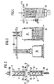
- FIG. 1 shows the formation of a roll of glass fiber insulation felt according to the traditional mode as described for example in French patent application No. 2,553,744.
- Fiber felt 1 usually comes directly from a production line.
- the winding of the felt without deterioration is possible when its density before compression is not too high.
- the coiled felts In the compressed state, the coiled felts generally have a density which is not greater than 65 kg / m 3 .
- coiled felts do not, before compression, have a density greater than 30 kg / m 3 .
- the denser felts are preferably packaged in the form of more or less compressible flat panels.
- the felt 1 is wound on itself, in the example shown, between two conveyor belts 2, 3 and a roller 4. According to the mode described in the aforementioned patent application, the compression of the felt in the roller 5 is ensured by a programmed movement of the roller 4.
- a sheet 6 of paper or of plastic material envelops the roll formed.
- This sheet intended to maintain the roller 5 in the compressed state which is imposed on it, is bonded to itself in a known manner for example by a line of glue or by heat-sealing.
- a sheet of a heat-shrinkable polymer for example a sheet of polyethylene, is used as the envelope for each roll.
- a heat-shrinkable sheet slightly wider than the roll, it is possible to at least partially protect the ends of the roll.
- the ends of the envelope are subjected to a heat treatment.
- the resulting retraction in fact folds the parts of the sheet which project on each side of the roll on the ends of the latter. These ends are thus protected against deterioration which could arise from subsequent handling.
- the roll covered with its envelope (if necessary retracted) is then led into a device making it possible to join several of these rolls into a modular element intended to form the burden.
- the rolls are routed by traditional automatic means to a stacker 7 ( Figure 2).
- This stacker comprises means controlling the intake 38 which, coupled with counting means not shown, allows attempt to form batches of a specified number of rollers in the stacker.
- the walls 9 of the stacker are preferably adjustable, for example by means of jacks arranged laterally.
- the space offered to the rollers is delimited in length by a front stop.
- This stop is also adjustable according to the length of the rollers.
- This device 11 is formed by two vertical walls 12, adjustable like the walls 9 of the stacker.
- rollers are held by stops not shown.
- This device is closed by a movable wall 48 whose translational movements are ensured by means such as a jack 14 or similar means.
- the inlet of the device 11 is opened and closed by means 46, 47 which can form a stop capable of supporting the compression force which is imposed on the rollers 5.
- a double belt film 16 is placed at the entrance to the device 11. It takes place from the reels 17.
- rollers 42, 43 on which these two films pass are driven in the same opening and closing movement as the stop rollers 46, 47 to allow the felt rollers 5 to enter the device 11.
- a welding assembly for the two films is placed immediately above the stop rollers.
- the rolls or, in FIG. 9, the packages of parallelepiped shape transported for example by a conveyor belt 37 are present at the entrance of the stacker 7 flat and in the direction of their length.
- the first package is driven above the stacker and by sliding on two retractable arms 38, comes to bear on the front stop 36.
- the upper arms 38 close immediately to receive the second package and the previous cycle is reproduced until the number of packages programmed for the formation of a module is reached.
- the lower arms 39 of the stacker disappear and all of the packages contained in the stacker descend by gravity onto the belt film 16 stretched between the two sets of pinch rollers 40, 41, and resting on film guide rollers 42, 43.
- the guide rollers are integral with the assembly, not shown, supporting sealing bars 44, 45 and two movable roller stops 46, 47. Depending on its position, this assembly releases or closes the input of the device 11.
- the two pinch roller assemblies 40, 41 deliver the film 16 as the module descends between the adjustable walls 12 of the device 11.
- the two upper stops 46, 47 close (left part of FIG. 9) and the pinch rollers 40, 41 stop the unwinding of the belt film.
- a new batch batch formation cycle is started in the stacker 7.
- the walls 12 can deviate slightly, the bottom of the device moves vertically from bottom to top driven by a mechanical chain system, not shown, controlled by a motor-variator.
- This system can be replaced by a pneumatic or hydraulic cylinder 14.
- the packages forming the module are then compressed between the stops 46, 47 and the conveyor 48.
- the conveyor 48 stops.
- the puppets 49, 50 helped by the pinch rollers 40, 41 and the rollers of the stops 46, 47 continue to bring back the excess film until a detection system, placed on the puppets 49, 50 (same length of film to be brought back for the same number of packages at the same compression) controls their stopping. The film is thus stretched over the module.
- the sealing bars 44, 45 are closed on the two strands of film which are welded, then cut by a cold cutting system.
- the support belt is made.
- the bars of welding 44, 45 open and the jacks 49, 50 recover the "residual slack of the film after separation of the pinch rollers 40, 41. The latter then close while awaiting a new package.
- the conveyor 48 on which the module now rests surrounded by its belt, descends to its starting level to evacuate the package to the stacking table.
- the films 16 surrounding the modular element extend over the major part of the packages.
- the belt thus produced resting on a large surface does not tend to penetrate the felt. It is therefore not necessary to have rigid protective elements between these means which surround the packages and the packages themselves, as is the case in the prior techniques using strapping by means of thin links.
- the belt covers at least two thirds of the length of the packages.
- the film used is advantageously a polyethylene film, of thickness between 40 and 100 micrometers.
- the compression which is imposed varies according to the compression ratio at the winding. It goes without saying that the higher the initial compression ratio, the lower the deformation which can be imposed without altering the quality of the felts. However, even for very high compression ratios during winding, some deformation is possible during the formation of the module. In general, the reduction in volume following compression and belting of the module can be as low as 7% or less for the most previously compressed products. For the others, the compression can be higher but preferably does not exceed 20%.
- the compression of the rollers in all cases forms flats in the areas where they are in contact with each other. This deformation ensures good stability of the module provided that the number of rollers is not too high.
- the number of rollers should not exceed 6 and preferably is 3 or 4.
- the traditional dimensions of the rolls and those of the bundles formed control these numbers.
- the diameter of the rollers is usually between 600 mm and 300 mm.
- a typical example according to the invention corresponds to felts with a density 11.5 kg / m 3 at the nominal thickness (that is to say guaranteed for use) of 80 mm and 9 m in length. These felts are wound with a compression ratio of 5.7 in rolls with a diameter of approximately 400 mm, which are assembled in modular elements comprising 4 rolls.
- the belt film reduces all four rollers to a height of 1550 mm, i.e. less than 5% compression. Stability in this case results from the friction which is exerted between the belt film and the envelope of the rollers and also from deformations of the rollers themselves.
- the modular elements in the form presented in FIG. 1, are removed laterally from the compression device and are taken up by a conveyor 21. They are brought flat to a lifting table 22 on which several modules are stacked by traditional means automatic handling.
- an adhesive can be applied to their contacting faces.
- the adhesive is preferably located on the film surrounding each module.
- a stack of modules on their face is less stable for the formation of high loads than that corresponding to the rollers in vertical position.
- the rollers are less deformable under the effect of a load in the direction of their length.
- a group of modules constituted as indicated above is then preferably arranged vertically by tilting.
- the layer of modules thus formed, in which the rollers are arranged vertically, is gripped by means of a gripper 24 and deposited on a pallet 25.
- a gripper 24 is gripped by means of a gripper 24 and deposited on a pallet 25.
- this layer that is to say the height of the rollers in vertical position, 2 or more layers are superimposed.
- the vertical stability of the assembly produced under these conditions is such that after formation of the burden, as will be indicated below, it is possible without risk of collapse, to stack several burdens on the storage areas.
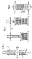
- the pallet carrying the set of two superimposed layers of modules passes over a traditional type wrapping machine.
- This machine shown diagrammatically at 23 comprises a rotary table 26 along a vertical axis.
- the wrapping machine comprises a plate 33 movable in the vertical direction. This plate is applied to the top of the load which it maintains in position during the operation. To this end, the pressure plate is movable in rotation along the same axis as that of the rotary table 26.
- a frame supports a vertically movable carriage.
- the carriage carries an arm on which is disposed a reel 27 and a pre-stretching and tension regulation system making it possible to apply the film with a determined tension on the bundle.
- This tension as indicated previously, can be variable so as for example to reduce the compression at the corners of the load.
- this type of traditional machine allows the end of the film to be placed on the load to be wrapped, the rotation of the load driven by the rotary table with simultaneous progression of the carriage carrying the reel in a vertical direction.
- the speed of progression is also adjustable which makes it possible to vary the overlap of the successive turns, and in general the vertical movement can be programmed so that the progression takes place in a differentiated manner according to the level of the load concerned.
- This type of machine also allows the automatic installation of a cap at the top of the load.
- the fitting of the cap is carried out by an assembly arranged on a mobile carriage moving on a horizontal rail.
- the assembly of the rail and the carriage which it carries is fixed on the vertical frame and can be adjusted according to the height of the burden to be covered.
- the carriage carries a reel for the film constituting the cap and means for cutting the film.
- the pressure plate is raised (in dotted position in Figures 2 and 6), the carriage and its reel, shown diagrammatically at 54, pass over the burden by unrolling the film which covers the top of the burden.
- the carriage having placed the film, it is cut and is completely detached from the assembly carried by the carriage to deposit on the burden.
- the pressure plate 33 is then lowered to maintain the burden again.
- the fitting of the cap 55 can be carried out advantageously after the upward wrapping and before the downward wrapping to maintain it while making a coating protecting the burden against the weather.
- a polyethylene film 20 micrometers thick and 500 mm wide is advantageously used.
- the thickness of the film is chosen so that it lends itself to a certain extension.
- a thickness of between 15 and 25 micrometers is chosen.
- This film is wound in coils which overlap for half. A double upward and downward winding is carried out with the installation at the top of a polyethylene cap of 50 to 180 micrometers.
- the stability of the assembly thus constituted is remarkable. It allows the stacking of two loads one on the other without the addition of any intermediate element.
- the solidity of the assembly is such that it allows transport on flat wagons with the simple fixing of straps passed through "stanchions”.
- the burden of the type of the invention has the advantage of being able to be successively broken down into layers then into modules and rolls as and when required, the part of the burden not used remaining in the form of an assembly stable.
- the product consists of rectangular felt panels.
- These panels are grouped in unit packages in which they are compressed. Traditionally, this brings together in a single envelope 3 to 20 panels per package.
- the number of panels is preferably such that the height of the panels (that is to say the sum of the thicknesses) in the compressed state is not greater than the width of these panels. This makes it possible to avoid deformations of the packages which would be detrimental to the formation of the modules and then stable burdens.
- the compression ratio in the unit packages does not usually exceed 2 and is most often around 1 , 5.
- the panels delivered by a stacker 28 in predetermined number are compressed between two converging conveyors 29 and 30. At the end of this compression, they are wrapped in a shrinkable polymer sheet while being kept in the compressed state.
- the polymer shell is formed from of a double sheet coming from the reels 31.
- the double sheet previously welded, is driven by the progression of the panels.
- the two sheets are folded over the rear face of the assembly and are welded at the end.
- the sheets are welded to each other along two very close parallel lines.
- the sheets are cut between the two weld lines.
- the package thus formed, the envelope is retracted at the ends by heating.
- the packages thus wrapped are directed as before to a stacker 7 and a device 11 for the constitution of a modular element 32 ( Figure 6).
- the same installation is used for the rolls and for the packages of panels if necessary by modifying the dimensions by means of the adjustable side walls and the longitudinal stops.
- the main difference at this stage of packaging comes from the fact that it is advantageous for the formation of the module to carry out a substantial additional compression of the panels.
- the belt of the modules is not subjected to thermal shrinkage.
- the compression is obtained by the play of the device 11.
- a compression is imposed slightly greater than that which one wants to establish in the module to be formed, then after having welded the film intended to form the belt, the pressure by the movable wall 13 being released, the belted packages stretch the film which maintains adequate compression.
- the modules are made up of 3 unit packages. In other advantageous examples, the modules consist of 4 or 5 packages.
- modules are stacked on a pallet by gripping arms, in a determined number, so as to constitute a burden of dimensions suitable for storage and transport.
- the burden created is then wrapped under the same conditions as above ( Figure 8).
- the wrapping is carried out under the same conditions as for the rolls.
Landscapes
- Engineering & Computer Science (AREA)
- Mechanical Engineering (AREA)
- Basic Packing Technique (AREA)
- Auxiliary Devices For And Details Of Packaging Control (AREA)
Claims (10)
Applications Claiming Priority (2)
| Application Number | Priority Date | Filing Date | Title |
|---|---|---|---|
| FR8514181A FR2587682B1 (fr) | 1985-09-25 | 1985-09-25 | Constitution de fardeaux d'isolants thermiques fibreux |
| FR8514181 | 1985-09-25 |
Publications (2)
| Publication Number | Publication Date |
|---|---|
| EP0220980A1 EP0220980A1 (de) | 1987-05-06 |
| EP0220980B1 true EP0220980B1 (de) | 1989-11-23 |
Family
ID=9323223
Family Applications (1)
| Application Number | Title | Priority Date | Filing Date |
|---|---|---|---|
| EP86402104A Expired EP0220980B1 (de) | 1985-09-25 | 1986-09-25 | Bildung von Ladungen faseriger Wärmeisolierstoffe |
Country Status (5)
| Country | Link |
|---|---|
| EP (1) | EP0220980B1 (de) |
| DE (1) | DE3667044D1 (de) |
| FR (1) | FR2587682B1 (de) |
| IE (1) | IE60164B1 (de) |
| TR (1) | TR22637A (de) |
Cited By (5)
| Publication number | Priority date | Publication date | Assignee | Title |
|---|---|---|---|---|
| EP0524062A1 (de) * | 1991-07-15 | 1993-01-20 | Isover Saint-Gobain | Verfahren zur Herstellung einer Ladung von Rollen aus zusammendrückbarem Material |
| WO2004103821A1 (fr) | 2003-05-22 | 2004-12-02 | Knauf Insulation Sa | Paquets de rouleaux et leur procede de fabrication |
| DE102006033680A1 (de) * | 2006-07-20 | 2008-01-24 | Saint-Gobain Isover G+H Ag | Verfahren und Vorrichtung zur Herstellung eines Gebindes aus einer Mehrzahl von Einzelpaketen sowie derartiges Gebinde |
| EP2206656A1 (de) | 2009-01-13 | 2010-07-14 | URSA Insulation, S.A. | Verpackung für Mineralwolleprodukte, Module zum Formen einer solchen Verpackung und Herstellungsverfahren für eine solche Verpackung |
| WO2013030401A3 (de) * | 2011-09-02 | 2013-05-02 | Hi Tech Textile Holding Gmbh | Verpackungseinrichtung für pressballen mit einer transportvorrichtung |
Families Citing this family (16)
| Publication number | Priority date | Publication date | Assignee | Title |
|---|---|---|---|---|
| DE10152385B4 (de) * | 2001-10-24 | 2012-11-22 | Saint-Gobain Isover G+H Ag | Großgebinde aus mehreren jeweils zu einer Rolle gewickelten, folienverpackten Dämmstoffbahnen aus Mineralwolle, insbesondere Glaswolle |
| ES2049571B1 (es) * | 1991-06-24 | 1996-08-16 | Consorcio Valenciano De Ingeni | Procedimiento para el empaquetado a presion de productos susceptibles de ser prensados y retractilado del paquete. |
| FR2719282B1 (fr) * | 1994-04-27 | 1996-05-31 | Tictor Sa | Dispositif de compression et d'emballage d'une pile de produits compressibles. |
| US5512346A (en) * | 1994-09-21 | 1996-04-30 | Owens-Corning Fiberglas Technology, Inc. | Insulation assembly for compressible insulation material |
| IT1282272B1 (it) * | 1994-10-03 | 1998-03-16 | Grafica Sds Di D Alonzo L & C | Maglietta del tipo t-shirts compressa e procedimento per la sua realizzazione. |
| DE20018106U1 (de) * | 2000-10-23 | 2001-01-11 | SAINT-GOBAIN ISOVER G+H AG, 67059 Ludwigshafen | Transporteinheit aus Dämmstoffpaketen |
| ITFI20010135A1 (it) | 2001-07-13 | 2003-01-13 | Gualchierani Textile Automatio | Pressa per la formazione di balle di materiale tessile od altro,con dispositivo di rivestimento mediante un telo |
| DE10317392A1 (de) * | 2003-04-15 | 2004-11-04 | Saint-Gobain Isover G+H Ag | Großgebinde für Transport und Lagerung von Dämmstoffelementen sowie Module aus Dämmstoffelementen hierfür |
| DE102005020892A1 (de) * | 2005-05-04 | 2006-11-09 | Saint-Gobain Isover G+H Ag | Verpackungseinheit für Rohrschalen |
| EP1777170A1 (de) | 2005-10-18 | 2007-04-25 | Knauf Insulation SA | Gebinde aus Rollen oder Platten aus Isoliermaterial |
| CN102633126A (zh) * | 2012-04-19 | 2012-08-15 | 句容金猴机械研究所有限公司 | 辊压彩瓦生产设备中的自动码垛系统 |
| FR3055321B1 (fr) | 2016-08-30 | 2018-08-31 | Saint-Gobain Isover | Paquet de produits isolants compressibles et procede de fabrication d'un tel paquet |
| FR3055322B1 (fr) | 2016-08-30 | 2021-06-18 | Saint Gobain Isover | Module comprenant des produits isolants et procede de fabrication d'un tel module |
| ES3035733T3 (en) * | 2016-12-20 | 2025-09-08 | Essity Hygiene & Health Ab | Method of compressing tissue bundles |
| EP4574704A1 (de) | 2023-12-20 | 2025-06-25 | Saint-Gobain Isover | Modul zum transport und zur lagerung von isolierrollen oder -platten, lager- und transporteinheit |
| EP4628422A1 (de) | 2024-04-05 | 2025-10-08 | Saint-Gobain Isover | Modul zum transport und zur lagerung von isolierrollen oder -platten |
Citations (1)
| Publication number | Priority date | Publication date | Assignee | Title |
|---|---|---|---|---|
| EP0119032A1 (de) * | 1983-03-05 | 1984-09-19 | Distribution Development (Reading) Limited | Verpackungsmaschine |
Family Cites Families (2)
| Publication number | Priority date | Publication date | Assignee | Title |
|---|---|---|---|---|
| JPS5940683B2 (ja) * | 1980-12-13 | 1984-10-02 | シンワ化学工業株式会社 | 複合ストレツチ・フイルムによるパレツト・ストレツチ包装方法 |
| FR2510515B1 (fr) * | 1981-07-31 | 1985-12-06 | Saint Gobain Isover | Procede pour le conditionnement de panneaux d'un materiau compressible et conditionnements realises par ce procede |
-
1985
- 1985-09-25 FR FR8514181A patent/FR2587682B1/fr not_active Expired
-
1986
- 1986-09-10 IE IE241486A patent/IE60164B1/en not_active IP Right Cessation
- 1986-09-24 TR TR37503A patent/TR22637A/xx unknown
- 1986-09-25 DE DE8686402104T patent/DE3667044D1/de not_active Expired
- 1986-09-25 EP EP86402104A patent/EP0220980B1/de not_active Expired
Patent Citations (1)
| Publication number | Priority date | Publication date | Assignee | Title |
|---|---|---|---|---|
| EP0119032A1 (de) * | 1983-03-05 | 1984-09-19 | Distribution Development (Reading) Limited | Verpackungsmaschine |
Cited By (9)
| Publication number | Priority date | Publication date | Assignee | Title |
|---|---|---|---|---|
| EP0524062A1 (de) * | 1991-07-15 | 1993-01-20 | Isover Saint-Gobain | Verfahren zur Herstellung einer Ladung von Rollen aus zusammendrückbarem Material |
| FR2679200A1 (fr) * | 1991-07-15 | 1993-01-22 | Saint Gobain Isover | Procede de realisation d'une charge de rouleaux de materiaux compressibles et dispositif de mise en óoeuvre. |
| WO2004103821A1 (fr) | 2003-05-22 | 2004-12-02 | Knauf Insulation Sa | Paquets de rouleaux et leur procede de fabrication |
| BE1015523A3 (fr) | 2003-05-22 | 2005-05-03 | Knauf Insulation S A | Paquets de rouleaux et leur procede de fabrication. |
| DE102006033680A1 (de) * | 2006-07-20 | 2008-01-24 | Saint-Gobain Isover G+H Ag | Verfahren und Vorrichtung zur Herstellung eines Gebindes aus einer Mehrzahl von Einzelpaketen sowie derartiges Gebinde |
| EP2206656A1 (de) | 2009-01-13 | 2010-07-14 | URSA Insulation, S.A. | Verpackung für Mineralwolleprodukte, Module zum Formen einer solchen Verpackung und Herstellungsverfahren für eine solche Verpackung |
| WO2010081779A1 (en) | 2009-01-13 | 2010-07-22 | Ursa Insulation S.A. | Package for mineral wool products, modules to form such package and process to manufacture such a package |
| WO2013030401A3 (de) * | 2011-09-02 | 2013-05-02 | Hi Tech Textile Holding Gmbh | Verpackungseinrichtung für pressballen mit einer transportvorrichtung |
| US9650166B2 (en) | 2011-09-02 | 2017-05-16 | Hi Tech Textile Holding Gmbh | Transporting device for pressed bales |
Also Published As
| Publication number | Publication date |
|---|---|
| IE862414L (en) | 1987-03-25 |
| EP0220980A1 (de) | 1987-05-06 |
| FR2587682B1 (fr) | 1987-12-18 |
| IE60164B1 (en) | 1994-06-15 |
| TR22637A (tr) | 1988-01-29 |
| FR2587682A1 (fr) | 1987-03-27 |
| DE3667044D1 (en) | 1989-12-28 |
Similar Documents
| Publication | Publication Date | Title |
|---|---|---|
| EP0220980A1 (de) | Bildung von Ladungen faseriger Wärmeisolierstoffe | |
| EP0533520B1 (de) | Verfahren und Vorrichtung zum Verpacken von palletierten Ladungen | |
| EP0977690B1 (de) | Pappschachtel zum verpacken einer gruppe von artikeln | |
| EP1633630B1 (de) | Rollenpackungen und ihr herstellungsverfahren | |
| FR2628391A1 (fr) | Appareils de regroupement d'articles et procedes de regroupement, d'empilage, d'emballage et de stabilisation d'articles | |
| EP0592314B1 (de) | Verfahren und Vorrichtung zum Verpacken von zusammendrückbaren Isolationsprodukten | |
| EP0645309A1 (de) | Verfahren und Vorrichtung zur Anpassung der Höhe einer Verpackung an die Höhe ihres Inhalts und Schneidevorrichtung dafür | |
| FR2716641A1 (fr) | Procédé et dispositif pour réaliser des supports de palette et palettes comportant de tels supports. | |
| EP0679579A1 (de) | Vorrichtung zum Komprimieren und Verpacken eines Stapels von komprimierbaren Gegenständen | |
| EP3507207B1 (de) | Verpackung von isolierprodukten und verfahren zur herstellung solch einer verpackung | |
| FR2470055A1 (fr) | Procede d'emballage d'un groupement d'articles et charge emballee par ledit procede | |
| FR2628390A1 (fr) | Appareil et procede de regroupement d'articles par enveloppement | |
| FR2926287A1 (fr) | Dispositif d'emballage | |
| FR2635079A1 (de) | ||
| EP0465370A2 (de) | Verfahren zum Umhüllen einer palettisierten Ladung mit einer Haube aus Dehnfolie | |
| EP0524062B2 (de) | Verfahren zur Herstellung einer Ladung von Rollen aus zusammendrückbarem Material | |
| FR2861365A1 (fr) | Procede de conditionnement d'un materiau isolant aere souple en le | |
| FR2604654A1 (fr) | Machine pour la fabrication d'emballage de produits sous feuilles retractables | |
| EP0465329A2 (de) | Verbundbahn und Vorrichtung zum Herstellen von sterilen, warmgeformten Verpackungen | |
| EP3924260A1 (de) | Umwicklungsverfahren und umwicklungsmaschine | |
| EP0919469B1 (de) | Verfahren und automatische Verpackungsstrasse für parallelepipedische Pakete | |
| EP3507206A1 (de) | Isolierendes produktmodul und verfahren zur herstellung eines derartigen moduls | |
| FR2727935A1 (fr) | Procede de realisation d'un emballage facile a ouvrir et emballage realise par celui-ci | |
| BE675630A (de) |
Legal Events
| Date | Code | Title | Description |
|---|---|---|---|
| PUAI | Public reference made under article 153(3) epc to a published international application that has entered the european phase |
Free format text: ORIGINAL CODE: 0009012 |
|
| AK | Designated contracting states |
Kind code of ref document: A1 Designated state(s): BE CH DE FR GB IT LI LU NL SE |
|
| 17P | Request for examination filed |
Effective date: 19870807 |
|
| 17Q | First examination report despatched |
Effective date: 19880414 |
|
| GRAA | (expected) grant |
Free format text: ORIGINAL CODE: 0009210 |
|
| AK | Designated contracting states |
Kind code of ref document: B1 Designated state(s): BE CH DE FR GB IT LI LU NL SE |
|
| REF | Corresponds to: |
Ref document number: 3667044 Country of ref document: DE Date of ref document: 19891228 |
|
| ITF | It: translation for a ep patent filed | ||
| GBT | Gb: translation of ep patent filed (gb section 77(6)(a)/1977) | ||
| PLBE | No opposition filed within time limit |
Free format text: ORIGINAL CODE: 0009261 |
|
| STAA | Information on the status of an ep patent application or granted ep patent |
Free format text: STATUS: NO OPPOSITION FILED WITHIN TIME LIMIT |
|
| 26N | No opposition filed | ||
| ITTA | It: last paid annual fee | ||
| EPTA | Lu: last paid annual fee | ||
| EAL | Se: european patent in force in sweden |
Ref document number: 86402104.3 |
|
| REG | Reference to a national code |
Ref country code: GB Ref legal event code: IF02 |
|
| PGFP | Annual fee paid to national office [announced via postgrant information from national office to epo] |
Ref country code: NL Payment date: 20050904 Year of fee payment: 20 |
|
| PGFP | Annual fee paid to national office [announced via postgrant information from national office to epo] |
Ref country code: FR Payment date: 20050908 Year of fee payment: 20 |
|
| PGFP | Annual fee paid to national office [announced via postgrant information from national office to epo] |
Ref country code: LU Payment date: 20050913 Year of fee payment: 20 |
|
| PGFP | Annual fee paid to national office [announced via postgrant information from national office to epo] |
Ref country code: BE Payment date: 20050915 Year of fee payment: 20 |
|
| PGFP | Annual fee paid to national office [announced via postgrant information from national office to epo] |
Ref country code: GB Payment date: 20050921 Year of fee payment: 20 |
|
| PGFP | Annual fee paid to national office [announced via postgrant information from national office to epo] |
Ref country code: IT Payment date: 20050927 Year of fee payment: 20 |
|
| PGFP | Annual fee paid to national office [announced via postgrant information from national office to epo] |
Ref country code: CH Payment date: 20050928 Year of fee payment: 20 |
|
| PGFP | Annual fee paid to national office [announced via postgrant information from national office to epo] |
Ref country code: SE Payment date: 20051005 Year of fee payment: 20 Ref country code: DE Payment date: 20051005 Year of fee payment: 20 |
|
| REG | Reference to a national code |
Ref country code: GB Ref legal event code: PE20 |
|
| PG25 | Lapsed in a contracting state [announced via postgrant information from national office to epo] |
Ref country code: GB Free format text: LAPSE BECAUSE OF EXPIRATION OF PROTECTION Effective date: 20060924 |
|
| PG25 | Lapsed in a contracting state [announced via postgrant information from national office to epo] |
Ref country code: NL Free format text: LAPSE BECAUSE OF EXPIRATION OF PROTECTION Effective date: 20060925 |
|
| REG | Reference to a national code |
Ref country code: CH Ref legal event code: PL |
|
| EUG | Se: european patent has lapsed | ||
| NLV7 | Nl: ceased due to reaching the maximum lifetime of a patent |
Effective date: 20060925 |
|
| BE20 | Be: patent expired |
Owner name: *ISOVER SAINT-GOBAIN Effective date: 20060925 |