EP0222994B1 - Analyseur de gaz pour la mesure simultanée d'une pluralité de substances - Google Patents
Analyseur de gaz pour la mesure simultanée d'une pluralité de substances Download PDFInfo
- Publication number
- EP0222994B1 EP0222994B1 EP86111873A EP86111873A EP0222994B1 EP 0222994 B1 EP0222994 B1 EP 0222994B1 EP 86111873 A EP86111873 A EP 86111873A EP 86111873 A EP86111873 A EP 86111873A EP 0222994 B1 EP0222994 B1 EP 0222994B1
- Authority
- EP
- European Patent Office
- Prior art keywords
- ratio
- diluting
- gas
- flow
- sample gas
- Prior art date
- Legal status (The legal status is an assumption and is not a legal conclusion. Google has not performed a legal analysis and makes no representation as to the accuracy of the status listed.)
- Expired - Lifetime
Links
- 239000004615 ingredient Substances 0.000 title claims description 25
- 238000005259 measurement Methods 0.000 title claims description 8
- 238000007865 diluting Methods 0.000 claims description 92
- 230000003247 decreasing effect Effects 0.000 claims description 6
- 238000010790 dilution Methods 0.000 claims description 6
- 239000012895 dilution Substances 0.000 claims description 6
- 239000007789 gas Substances 0.000 description 121
- 239000000523 sample Substances 0.000 description 82
- 239000012159 carrier gas Substances 0.000 description 14
- IJGRMHOSHXDMSA-UHFFFAOYSA-N Atomic nitrogen Chemical compound N#N IJGRMHOSHXDMSA-UHFFFAOYSA-N 0.000 description 12
- QVGXLLKOCUKJST-UHFFFAOYSA-N atomic oxygen Chemical compound [O] QVGXLLKOCUKJST-UHFFFAOYSA-N 0.000 description 6
- 238000000605 extraction Methods 0.000 description 6
- 229910052757 nitrogen Inorganic materials 0.000 description 6
- 239000001301 oxygen Substances 0.000 description 6
- 229910052760 oxygen Inorganic materials 0.000 description 6
- 239000012535 impurity Substances 0.000 description 5
- 238000010586 diagram Methods 0.000 description 3
- 238000010438 heat treatment Methods 0.000 description 2
- OKTJSMMVPCPJKN-UHFFFAOYSA-N Carbon Chemical compound [C] OKTJSMMVPCPJKN-UHFFFAOYSA-N 0.000 description 1
- UFHFLCQGNIYNRP-UHFFFAOYSA-N Hydrogen Chemical compound [H][H] UFHFLCQGNIYNRP-UHFFFAOYSA-N 0.000 description 1
- -1 SiaN4 Chemical compound 0.000 description 1
- 239000003463 adsorbent Substances 0.000 description 1
- 238000006243 chemical reaction Methods 0.000 description 1
- 239000003795 chemical substances by application Substances 0.000 description 1
- 238000010276 construction Methods 0.000 description 1
- 239000012470 diluted sample Substances 0.000 description 1
- 239000006185 dispersion Substances 0.000 description 1
- 238000009826 distribution Methods 0.000 description 1
- 230000000694 effects Effects 0.000 description 1
- 229910002804 graphite Inorganic materials 0.000 description 1
- 239000010439 graphite Substances 0.000 description 1
- 239000001257 hydrogen Substances 0.000 description 1
- 229910052739 hydrogen Inorganic materials 0.000 description 1
- 239000011261 inert gas Substances 0.000 description 1
- 239000000463 material Substances 0.000 description 1
- 230000007246 mechanism Effects 0.000 description 1
- 239000000155 melt Substances 0.000 description 1
- 229910052751 metal Inorganic materials 0.000 description 1
- 239000002184 metal Substances 0.000 description 1
- 150000002739 metals Chemical class 0.000 description 1
- 239000007800 oxidant agent Substances 0.000 description 1
- 230000001590 oxidative effect Effects 0.000 description 1
- KJFMBFZCATUALV-UHFFFAOYSA-N phenolphthalein Chemical compound C1=CC(O)=CC=C1C1(C=2C=CC(O)=CC=2)C2=CC=CC=C2C(=O)O1 KJFMBFZCATUALV-UHFFFAOYSA-N 0.000 description 1
- 238000010926 purge Methods 0.000 description 1
- 229910021332 silicide Inorganic materials 0.000 description 1
- FVBUAEGBCNSCDD-UHFFFAOYSA-N silicide(4-) Chemical compound [Si-4] FVBUAEGBCNSCDD-UHFFFAOYSA-N 0.000 description 1
Images


Classifications
-
- G—PHYSICS
- G05—CONTROLLING; REGULATING
- G05D—SYSTEMS FOR CONTROLLING OR REGULATING NON-ELECTRIC VARIABLES
- G05D11/00—Control of flow ratio
- G05D11/02—Controlling ratio of two or more flows of fluid or fluent material
- G05D11/13—Controlling ratio of two or more flows of fluid or fluent material characterised by the use of electric means
- G05D11/131—Controlling ratio of two or more flows of fluid or fluent material characterised by the use of electric means by measuring the values related to the quantity of the individual components
- G05D11/132—Controlling ratio of two or more flows of fluid or fluent material characterised by the use of electric means by measuring the values related to the quantity of the individual components by controlling the flow of the individual components
-
- G—PHYSICS
- G01—MEASURING; TESTING
- G01N—INVESTIGATING OR ANALYSING MATERIALS BY DETERMINING THEIR CHEMICAL OR PHYSICAL PROPERTIES
- G01N33/00—Investigating or analysing materials by specific methods not covered by groups G01N1/00 - G01N31/00
- G01N33/0004—Gaseous mixtures, e.g. polluted air
- G01N33/0009—General constructional details of gas analysers, e.g. portable test equipment
- G01N33/0027—General constructional details of gas analysers, e.g. portable test equipment concerning the detector
- G01N33/0031—General constructional details of gas analysers, e.g. portable test equipment concerning the detector comprising two or more sensors, e.g. a sensor array
-
- G—PHYSICS
- G01—MEASURING; TESTING
- G01N—INVESTIGATING OR ANALYSING MATERIALS BY DETERMINING THEIR CHEMICAL OR PHYSICAL PROPERTIES
- G01N33/00—Investigating or analysing materials by specific methods not covered by groups G01N1/00 - G01N31/00
- G01N33/20—Metals
- G01N33/202—Constituents thereof
- G01N33/2022—Non-metallic constituents
- G01N33/2025—Gaseous constituents
-
- G—PHYSICS
- G01—MEASURING; TESTING
- G01N—INVESTIGATING OR ANALYSING MATERIALS BY DETERMINING THEIR CHEMICAL OR PHYSICAL PROPERTIES
- G01N1/00—Sampling; Preparing specimens for investigation
- G01N1/28—Preparing specimens for investigation including physical details of (bio-)chemical methods covered elsewhere, e.g. G01N33/50, C12Q
- G01N1/38—Diluting, dispersing or mixing samples
-
- Y—GENERAL TAGGING OF NEW TECHNOLOGICAL DEVELOPMENTS; GENERAL TAGGING OF CROSS-SECTIONAL TECHNOLOGIES SPANNING OVER SEVERAL SECTIONS OF THE IPC; TECHNICAL SUBJECTS COVERED BY FORMER USPC CROSS-REFERENCE ART COLLECTIONS [XRACs] AND DIGESTS
- Y10—TECHNICAL SUBJECTS COVERED BY FORMER USPC
- Y10T—TECHNICAL SUBJECTS COVERED BY FORMER US CLASSIFICATION
- Y10T137/00—Fluid handling
- Y10T137/8593—Systems
- Y10T137/87265—Dividing into parallel flow paths with recombining
- Y10T137/87281—System having plural inlets
-
- Y—GENERAL TAGGING OF NEW TECHNOLOGICAL DEVELOPMENTS; GENERAL TAGGING OF CROSS-SECTIONAL TECHNOLOGIES SPANNING OVER SEVERAL SECTIONS OF THE IPC; TECHNICAL SUBJECTS COVERED BY FORMER USPC CROSS-REFERENCE ART COLLECTIONS [XRACs] AND DIGESTS
- Y10—TECHNICAL SUBJECTS COVERED BY FORMER USPC
- Y10T—TECHNICAL SUBJECTS COVERED BY FORMER US CLASSIFICATION
- Y10T137/00—Fluid handling
- Y10T137/8593—Systems
- Y10T137/87265—Dividing into parallel flow paths with recombining
- Y10T137/87338—Flow passage with bypass
-
- Y—GENERAL TAGGING OF NEW TECHNOLOGICAL DEVELOPMENTS; GENERAL TAGGING OF CROSS-SECTIONAL TECHNOLOGIES SPANNING OVER SEVERAL SECTIONS OF THE IPC; TECHNICAL SUBJECTS COVERED BY FORMER USPC CROSS-REFERENCE ART COLLECTIONS [XRACs] AND DIGESTS
- Y10—TECHNICAL SUBJECTS COVERED BY FORMER USPC
- Y10T—TECHNICAL SUBJECTS COVERED BY FORMER US CLASSIFICATION
- Y10T137/00—Fluid handling
- Y10T137/8593—Systems
- Y10T137/87571—Multiple inlet with single outlet
- Y10T137/87676—With flow control
- Y10T137/87684—Valve in each inlet
-
- Y—GENERAL TAGGING OF NEW TECHNOLOGICAL DEVELOPMENTS; GENERAL TAGGING OF CROSS-SECTIONAL TECHNOLOGIES SPANNING OVER SEVERAL SECTIONS OF THE IPC; TECHNICAL SUBJECTS COVERED BY FORMER USPC CROSS-REFERENCE ART COLLECTIONS [XRACs] AND DIGESTS
- Y10—TECHNICAL SUBJECTS COVERED BY FORMER USPC
- Y10T—TECHNICAL SUBJECTS COVERED BY FORMER US CLASSIFICATION
- Y10T436/00—Chemistry: analytical and immunological testing
- Y10T436/11—Automated chemical analysis
- Y10T436/117497—Automated chemical analysis with a continuously flowing sample or carrier stream
- Y10T436/118339—Automated chemical analysis with a continuously flowing sample or carrier stream with formation of a segmented stream
Definitions
- the present invention relates to a gas analyzer for the simultaneous measurement of at least two kinds of gas contained in a sample gas.
- An analyzer using the second possibility is described in EP-A1 0 024 566. It is used for measuring gas which evaporates from a material being heated in a crucible. A change-over valve is used to first measure with the first detector and then to measure afterwards with the second detector.
- An analyzer using the first possibility is known from GB A 2 119 088.
- Said analyzer comprises the following features:
- the sample gas flow dividing/diluting means first branches the sample gas. To the branch flows diluting gas is added to such an extent that the concentration of a predetermined gas is the same in all branches, i.e. when the sample gas flow is decreased in a branch, the diluting gas flow is decreased by the same extent.
- an analyzer of the first possibility has the disadvantage that only one fixed dilution ratio can be adjusted at a time. This makes it difficult to measure different gases of very different concentrations. Another problem is that wrong measurements may be induced by backpressure effects from one detector to another detector arranged before said detector. When using a gas analyzer of the third possibility, measurement is very timeconsuming as one ingredient has to be measured after the other. Using a gas analyzer of the third possibility has the disadvantage that a very low gas flow is obtained when choosing the branching ratio low for measuring the concentration of a very concentrated ingredient.
- the gas analyzer according to the present invention has the features of the analyzer using the third possibility as described above whereby said sample gas flow dividing/diluting means comprises at least two flow-dividing ratio/diluting ratio setting means for automatically reducing - or increasing - the dilution ratio when increasing - or decreasing, respectively - the flow dividing ratio.
- said sample gas flow dividing/diluting means comprises at least two flow-dividing ratio/diluting ratio setting means for automatically reducing - or increasing - the dilution ratio when increasing - or decreasing, respectively - the flow dividing ratio.
- the advantage arises that the exit gas flow keeps high even when the sample gas flow is reduced.
- the dilution ratio is increased (reduced) to such an extent that the gas flow in the exit passage remains constant when the flow dividing ratio is decreased (increased), provided the pressures in the introducing passages remain constant.
- Such a device comprises a plurality of parallel passages, the entrances thereof being connectable exclusively either to the sample gas introducing passage or the diluting gas passage, the exit thereof being commonly connected to a respective exit passage. Due to the exclusive switching, always the same number of passages is used, each passage receiving either sample gas or diluting gas. Thereby automatically the feature is realized that the dividing ratio changes inversely to the diluting ratio.
- an ingredient previous rough concentration detector and a controller are used to supply adjusting values to said flow dividing ratio/diluting ratio setting means.
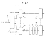
- the analyzer according to Fig. 1 comprises a plurality of gas concentration detectors D I , D II , etc. connected in parallel to a sample gas-introducing passage provided with sample gas flow-dividing means X which can divide said sample gas in an appointed ratio to feed said gas concentration detectors Dj, D II with the divided flows of said sample gas, and sample gas diluting means Y l , Y ll for further diluting the sample gas divided by said sample gas-dividing means.
- the functions of the sample gas dividing means X and the sample gas diluting means Yi, Yii are coupled in such a way that the diluting ratio is automatically increased in a branch when the dividing ratio for said branch is decreased, and inversely.
- Fig. 1 additionally shows that the following devices are arranged before the second detector D ll : an oxidyzer 6, a C0 2 gas remover 7, and a H 2 0 remover 8.
- Fig. 2 is a general rough view showing a gas analyzer comprising combined flow dividing ratio/diluting ratio setting means.
- This gas extraction type sample analyzer comprises, as shown in Fig. 2, a gas extraction portion A and a gas-analyzing portion B connected with said gas extraction portion A for simultaneously measuring two ingredients.
- Said gas extraction portion A comprises a heating furnace 1 (for example a graphite crucible) for extracting various kinds of ingredient gases (CO gas, N 2 gas, H 2 gas and the like) corresponding to various kinds of ingredients (in this embodiment oxygen, nitrogen, hydrogen and the like) by heating it in the presence of a carrier gas (an inert gas such as He gas) supplied via a carrier gas-introducing passage O to the melt in the furnace 1 and an electromagnetic purge valve 2.
- a heating furnace 1 for example a graphite crucible
- ingredient gases CO gas, N 2 gas, H 2 gas and the like
- ingredients in this embodiment oxygen, nitrogen, hydrogen and the like
- Said gas-analyzing portion B comprises a CO concentration measuring system I and a N 2 concentration measuring system II connected in parallel to a sample gas-introducing passage 3 connected with said electro-magnetic purga valve 2 of said gas extraction portion A.
- Said CO concentration measuring system I comprises a first sample gas passage 3 l branched from said sample gas-introducing passage 3, a first carrier gas passage O l branched from said carrier gas-introducing passage O, a first pressure-regulating governer 10 1 arranged between said first branched sample gas passage 3 1 and said first carrier gas passage O l , a first flow-dividing ratio/diluting ratio- setting device 11 1 connecting said first branched sample gas passage 3 l and said first carrier gas passage O l , a first pressure regulator 4i, a first flow rate-adjusting needle valve 5 1 , a first gas concentration detector Di comprising a non-dispersion type infrared detector for use in measuring of the concentration of CO gas provided via a first exit passage 12 1 from said first flow-dividing ratio/diluting ratio-setting device 11 l and a first exhaust passage 9 1 .
- said N 2 measuring system II comprises a second sample gas passage 3 11 branched from said sample gas-introducing passage 3, a second carrier gas passage O ll branched from said carrier gas-introducing passage O, a second pressure-regulating governor 10 ll arranged between said second sample gas passage 3 11 and said second carrier gas passage O ll , a second flow-dividing ratio/diluting ratio-setting devide 11 11 connecting said second branched sample gas passage 3 11 and said second carrier gas passage O ll , a second pressure regulator 4 11 , a second flow rate-adjusting needle valve 5 11 , an oxidizer 6 for oxidizing CO gas and H 2 gas contained in the sample gas, which passed through said first gas concentration detector Di, to be converted to C0 2 gas and H 2 0 gas, a C0 2 remover 7 for removing the resulting C0 2 gas by the chemical reaction between it and a C0 2 removing agent, a H 2 0 remover 8 for removing the resulting H 2 0 gas by a H 2 0 ad
- a portion encircled by a dotted line in Fig. 2, mainly comprising said first flow-dividing ratio/diluting ratio-setting devide 11 l and said second flow-dividing ratio/diluting ratio-setting device 11 ll shows a sample gas flow-dividing/diluting means Z which can be used both as a sample gas flow-dividing means X and a sample gas-diluting means Y l , Y ll described in Fig. 1 which is a schematic diagram of the basic concept of the present invention.
- Said sample gas flow-dividing/diluting means Z is adapted to divide a flow of the sample gas supplied through said sample gas-introducing passage 3 at an appointed ratio dilute the divided sample gas, and supply the first gas concentration detector D l and the second gas concentration detector D ll arranged in parallel to said sample gas-introducing passage 3 with the divided and diluted sample gas.
- said sample gas-diluting means Y l , Y ll comprises the flow-dividing ratio/diluting ratio-setting means 11 l , 11 ll , respectively, so as to be used in the cooperation also as said sample gas flow-dividing means X.
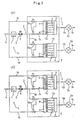
- each of said flow-dividing ratio/diluting ratio-setting means 11 1 , 1111 comprises an inlet side space a provided by said branched sample gas passage 3 l (3 ll ) connected therewith at one end side thereof and said carrier gas passage O l (O ll ) connected therewith at the other end side thereof, an outlet side space b from which said exit passage 12 l (12 ll ) extends, a plurality (5 pieces in this embodiment) of flow rate elements (for example capillaries) communicating with said inlet side space a with said outlet side space b designated by c ----, and a valve body d dividing said inlet side space a into a space of the side at which said branched sample gas passage 3 l (3 ll ) is connected and a space connected with said carrier gas passage O l (O ll ).
- Said plurality of flow rate elements (capillaries) c---used in this embodiment all have the same flow rate characteristics.
- the carrier gas (He gas) introduced through said carrier gas passage O l (O ll ) is used as a diluting gas in said flow-dividing ratio/diluting ratio-setting device 11 I (11 II ).
- Said valve body d of said inlet side space a is adapted to be positioned at optional positions marked in the drawing with (1), (2), (3), (4), (5), (6), respectively.
- each of said flow-dividing ratio/diluting ratio-setting devices 11 I 11 II ) it is optionally possible to adjust the flow-dividing ratio of the sample gas for each of said measuring systems I, II (said detectors D I , D II ) as well as the diluting ratio of the divided sample gas by setting optionally the position of said valve body d.
- the diluting ratio is automatically set to be small (accordingly, the total dilution extent is small) while when the flow-dividing ratio is set to be small, the diluting ratio is automatically set to be large (accordingly, the total dilution extent is large).
- the diluting ratio is automatically set to be small (accordingly, the total dilution extent is small) while when the flow-dividing ratio is set to be small, the diluting ratio is automatically set to be large (accordingly, the total dilution extent is large).
- the sample gas introduced through said sample gas-introducing passage 3 is transferred to the flow-dividing ratio/diluting ratio-setting devices 11 1 , 11 11 at a flow-dividing ratio of 3 : 2, and the sample gas transferred to the first flow-dividing ratio/diluting ratio-setting device 11 1 is diluted at a diluting ratio of 3/5 to be introduced into the measuring system I while the sample gas transferred to the second flow-dividing ratio/diluting ratio-setting device 11 is diluted at a diluting ratio of 2/5 to be introduced into the measuring system II.
- valve body d of the first flow-dividing ratio/diluting ratio-setting device 11 is set to a certain position, for example the position (2), and the valve body d of the second flow-dividing ratio/diluting ratio-setting device 11 II is set to another position, for example the position (5), as shown in Fig.
- valve body d of the first flow-dividing ratio/diluting ratio-setting device 11 1 is positioned for example at the position (5), and the valve body d of the second flow-dividing ratio/diluting ratio-setting device 11 11 is set to be positioned for example at the position (2), as shown in Fig.
- both the valve body d of the first flow-dividing ratio/diluting ratio-setting device 11 1 and that of the second flow-dividing ratio/diluting ratio-setting device 11 are set to be positioned for example at the position (6), whereby the sample gas introduced through the sample gas-introducing passage 3 is transferred to the flow-dividing ratio/diluting ratio-setting devices 11 1 , 1111 at a flow-dividing ratio of 1:1, and both the sample gas transferred to the first flow-dividing ratio/diluting ratio- setting device 11 1 and the sample gas transferred to the second flow-dividing ratio/diluting ratio-setting device 11 11 are diluted at a diluting ratio of 0/5, that is to say the sample gas flow is divided but not diluted.
- valve body d of the first flow-dividing ratio/diluting ratio-setting device 11 1 and the valve body d of the second flow-dividing ratio/diluting ratio-setting device 11 II can optionally be positioned at any suitable position such that many ingredients contained in a wide range of samples having various ingredient gas concentration distributions can be simultaneously measured with high ac- curracy by means of a single apparatus.
- Fig. 4 shows another preferred embodiment in which the sample gas-introducing passage 3 is provided with a previous concentration detector 13 for previously detecting rough concentrations of ingredients contained in a sample gas introduced therein, and the valve bodies d of the flow-dividing ratio/diluting ratio-setting devices 11 1 , 1111 are provided with actuating mechanisms e, respectively, whereby the valve bodies d is a automatically set to be positioned at the suitable position by means of a controller C on the basis of a rough concentration ratio of ingredient gases detected by said previous concentration detector 13.
- Other members are similar to those in the above described embodiment.
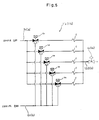
- Fig. 5 shows another preferred embodiment of the flow-dividing ratio/diluting ratio-setting device 11 1 (1111) comprising a plurality (five in this embodiment) of electro-magnetic three-way valves vi, v 2 - into which the branched passages from the branched sample gas passage 3 1 (3 11 ) and the branched passages from the carrier gas passage O I (O II ) are opening, and flow rate elements (for example capillaries) c, - connected with said electro- magnetic three-way valves vi, v 2 -.
- flow rate elements for example capillaries
- the flow-dividing ratio/diluting ratio-setting devices 11 1 , 1111 of such a construction provide for the same advantageous results as that of the flow-dividing ratio/diluting ratio-setting devices 111, 1111 of the above described embodiments.
- a gas analyzer capable of simultaneously measuring two ingredients was described by embodiments, it is within the scope of the present invention to also provide a gas analyzer for simultaneous measurement of many ingredients, i. e. for example more than three ingredients, as indicated in Fig. 1 which is a general sketch of the concept of the present invention.
- sample gas flow-dividing/diluting means Z in which a sample gas flow-dividing means X and sample gas-diluting means Y I , Y II are collected, has been described with the above, the expert may readily realize that the sample gas flow-dividing means X and the sample gas-diluting means Y I , Y II may be constructed as independent units.
Landscapes
- Chemical & Material Sciences (AREA)
- Engineering & Computer Science (AREA)
- Health & Medical Sciences (AREA)
- Life Sciences & Earth Sciences (AREA)
- Physics & Mathematics (AREA)
- General Physics & Mathematics (AREA)
- Analytical Chemistry (AREA)
- Medicinal Chemistry (AREA)
- Food Science & Technology (AREA)
- Biochemistry (AREA)
- General Health & Medical Sciences (AREA)
- Immunology (AREA)
- Pathology (AREA)
- Combustion & Propulsion (AREA)
- Automation & Control Theory (AREA)
- Sampling And Sample Adjustment (AREA)
Claims (4)
Applications Claiming Priority (2)
| Application Number | Priority Date | Filing Date | Title |
|---|---|---|---|
| JP23594385A JPH0619311B2 (ja) | 1985-10-19 | 1985-10-19 | 多成分同時測定用ガス分析装置 |
| JP235943/85 | 1985-10-19 |
Publications (2)
| Publication Number | Publication Date |
|---|---|
| EP0222994A1 EP0222994A1 (fr) | 1987-05-27 |
| EP0222994B1 true EP0222994B1 (fr) | 1990-10-31 |
Family
ID=16993522
Family Applications (1)
| Application Number | Title | Priority Date | Filing Date |
|---|---|---|---|
| EP86111873A Expired - Lifetime EP0222994B1 (fr) | 1985-10-19 | 1986-08-27 | Analyseur de gaz pour la mesure simultanée d'une pluralité de substances |
Country Status (4)
| Country | Link |
|---|---|
| US (1) | US4705669A (fr) |
| EP (1) | EP0222994B1 (fr) |
| JP (1) | JPH0619311B2 (fr) |
| DE (1) | DE3675340D1 (fr) |
Families Citing this family (53)
| Publication number | Priority date | Publication date | Assignee | Title |
|---|---|---|---|---|
| US5102806A (en) * | 1987-12-11 | 1992-04-07 | Horiba, Ltd. | Method for analyzing fluid by multi-fluid modulation mode |
| US5255072A (en) * | 1987-12-11 | 1993-10-19 | Horiba, Ltd. | Apparatus for analyzing fluid by multi-fluid modulation mode |
| DE3814917A1 (de) * | 1988-05-03 | 1989-11-16 | Kernforschungsz Karlsruhe | Gasmischer zur erzeugung eines kontinuierlichen gasmischstromes |
| US5338515A (en) * | 1990-08-17 | 1994-08-16 | Catalytica, Inc. | SO2 sensor |
| US5246668A (en) * | 1990-09-20 | 1993-09-21 | Space Biospheres Ventures | Air sampling and analysis system |
| JPH04130057U (ja) * | 1991-05-17 | 1992-11-30 | 三菱重工業株式会社 | 連続ガスサンプリング装置 |
| JP3077772B2 (ja) * | 1991-06-05 | 2000-08-14 | シスメックス株式会社 | 複数の分析モジュールを用いる粒子自動分析方法及び装置 |
| JPH0545284A (ja) * | 1991-08-17 | 1993-02-23 | Horiba Ltd | パーテイキユレート連続分析装置 |
| JPH0552755U (ja) * | 1991-12-17 | 1993-07-13 | 株式会社堀場製作所 | メタン分析装置 |
| US6013228A (en) * | 1992-06-01 | 2000-01-11 | The Coca-Cola Company | Method and system for sampling and determining the presence of compounds in containers using a pulsed fluorescence detector |
| DE4221692A1 (de) * | 1992-07-02 | 1994-01-05 | Siemens Ag | Verfahren und Vorrichtung zur Ermittlung eines Gemischanteils eines Gasgemisches |
| US5424539A (en) * | 1992-12-18 | 1995-06-13 | Finnegan Mat Gmbh | Process for the analysis of gaseous components by mass spectrometry |
| GB9318940D0 (en) * | 1993-09-14 | 1993-10-27 | Northumbrian Water Group Plc | Multi-sensor systems |
| US6399391B1 (en) | 1994-10-25 | 2002-06-04 | Robert L. Tomlin | Low cost total reduced sulfur analysis system |
| US6063633A (en) | 1996-02-28 | 2000-05-16 | The University Of Houston | Catalyst testing process and apparatus |
| US5939330A (en) * | 1996-08-02 | 1999-08-17 | Peterson; Roger | Method and apparatus for gathering and preparing liquid samples for analysis |
| DE19729492A1 (de) * | 1997-07-10 | 1999-02-11 | Forschungszentrum Juelich Gmbh | Verfahren und Vorrichtung zur Serienprobenahme |
| JP3434192B2 (ja) * | 1998-02-13 | 2003-08-04 | 株式会社堀場製作所 | 排気ガス分析装置およびその装置を用いたガストレース法によるモーダルマス解析方法 |
| US6149882A (en) | 1998-06-09 | 2000-11-21 | Symyx Technologies, Inc. | Parallel fixed bed reactor and fluid contacting apparatus |
| US7150994B2 (en) * | 1999-03-03 | 2006-12-19 | Symyx Technologies, Inc. | Parallel flow process optimization reactor |
| US20020042140A1 (en) * | 1999-03-03 | 2002-04-11 | Alfred Hagemeyer | Methods for analysis of heterogeneous catalysts in a multi-variable screening reactor |
| DE60108482T2 (de) | 2000-03-07 | 2006-02-16 | Symyx Technologies, Inc., Santa Clara | Prozessoptimierungsreaktor mit parallelem durchfluss |
| US6623699B1 (en) * | 2000-11-15 | 2003-09-23 | Leco Corporation | Analyzing system for high accuracy nitrogen determination |
| US7118917B2 (en) | 2001-03-07 | 2006-10-10 | Symyx Technologies, Inc. | Parallel flow reactor having improved thermal control |
| US6827903B2 (en) * | 2001-10-26 | 2004-12-07 | Leco Corporation | Inert gas fusion analyzer |
| US6895983B2 (en) * | 2002-09-26 | 2005-05-24 | The Chemithon Corporation | Method and apparatus for dividing the flow of a gas stream |
| WO2004088415A2 (fr) * | 2003-03-28 | 2004-10-14 | Advanced Technology Materials Inc. | Liberation de reactifs par modulation photometrique |
| US7063097B2 (en) * | 2003-03-28 | 2006-06-20 | Advanced Technology Materials, Inc. | In-situ gas blending and dilution system for delivery of dilute gas at a predetermined concentration |
| JP4770312B2 (ja) * | 2005-07-26 | 2011-09-14 | トヨタ自動車株式会社 | ガスの希釈器 |
| DE102006015535A1 (de) * | 2006-03-31 | 2007-10-04 | Thermo Electron (Bremen) Gmbh | Verfahren und Vorrichtung zur Analyse von Isotopenverhältnissen |
| US7928369B2 (en) * | 2006-03-31 | 2011-04-19 | Thermo Fisher Scientific (Bremen) Gmbh | Device for the analysis of isotope ratios |
| EP2104755A4 (fr) * | 2006-10-26 | 2011-01-12 | Symyx Solutions Inc | Réacteur à lit fixe parallèle à haute pression et son procédé |
| US20100081577A1 (en) * | 2008-09-30 | 2010-04-01 | Symyx Technologies, Inc. | Reactor systems and methods |
| US8181504B2 (en) * | 2009-02-18 | 2012-05-22 | Factory Mutual Insurance Company | Smoke evaluating device and related method |
| FR2946754B1 (fr) * | 2009-06-12 | 2012-05-18 | Alcatel Lucent | Dispositif et procede d'analyse de gaz,et station de mesure associee |
| US8945936B2 (en) | 2011-04-06 | 2015-02-03 | Fresenius Medical Care Holdings, Inc. | Measuring chemical properties of a sample fluid in dialysis systems |
| JP2013160594A (ja) | 2012-02-03 | 2013-08-19 | Horiba Ltd | 元素分析装置 |
| US9804109B2 (en) * | 2012-05-10 | 2017-10-31 | Design West Technologies, Inc. | System and method for chemical and/or biological detection |
| US10724137B2 (en) * | 2013-02-05 | 2020-07-28 | Kokusai Eletric Corporation | Cleaning method, method of manufacturing semiconductor device, substrate processing apparatus, recording medium, and cleaning completion determining method |
| JP6117159B2 (ja) * | 2014-09-17 | 2017-04-19 | 三菱重工業株式会社 | ガス採取装置及びガス分析方法 |
| US9943819B2 (en) | 2014-11-03 | 2018-04-17 | Singh Instrument LLC | Small-scale reactor having improved mixing |
| US11357966B2 (en) | 2015-04-23 | 2022-06-14 | B. Braun Medical Inc. | Compounding device, system, kit, software, and method |
| US10948470B2 (en) * | 2016-04-29 | 2021-03-16 | TricornTech Taiwan | System and method for in-line monitoring of airborne contamination and process health |
| US10330617B2 (en) | 2017-01-10 | 2019-06-25 | Design West Technologies, Inc. | Wearable sensor badge for toxic industrial chemicals |
| JP2018159699A (ja) * | 2017-03-23 | 2018-10-11 | 株式会社住化分析センター | 水素ガス中の不純物の濃縮キット、水素ガス中の不純物の濃縮方法、及び水素ガスの品質管理方法 |
| JP6956023B2 (ja) * | 2017-03-23 | 2021-10-27 | 株式会社住化分析センター | 水素ガス分析用キット、水素ガス分析方法、及び水素ガスの品質管理方法 |
| KR20190092732A (ko) * | 2018-01-31 | 2019-08-08 | (주)포인트엔지니어링 | 공기질 측정장치 |
| JP7007940B2 (ja) * | 2018-02-01 | 2022-02-10 | 株式会社住化分析センター | 水素ガス分析キット及び水素ガス分析方法 |
| US10935472B2 (en) * | 2018-03-07 | 2021-03-02 | Honeywell International Inc. | Pumped cooling system in gas detector |
| CZ2019399A3 (cs) * | 2019-06-21 | 2021-01-06 | Vysoká Škola Báňská-Technická Univerzita Ostrava | Analyzační linka zplodin hoření |
| JP6941650B2 (ja) * | 2019-09-20 | 2021-09-29 | ネッチ ゲレーテバウ ゲーエムベーハー | ガス分析装置、及びガス分析方法 |
| WO2024097764A1 (fr) * | 2022-11-02 | 2024-05-10 | Thermo Environmental Instruments Llc | Systèmes et procédés de surveillance de la concentration d'un composant de fluide échantillon |
| CN120948393B (zh) * | 2025-08-15 | 2026-02-06 | 北京绿蔓城农林科技有限公司 | 三检测器并行的土壤检测用氧氨氢分析仪 |
Family Cites Families (12)
| Publication number | Priority date | Publication date | Assignee | Title |
|---|---|---|---|---|
| US3080760A (en) * | 1960-06-29 | 1963-03-12 | American Cyanamid Co | Disposable sample probe for bulk chemicals |
| US3690833A (en) * | 1970-05-04 | 1972-09-12 | Damon Corp | Automated fluids analyzer having selectively interrupted flow |
| GB1364841A (en) * | 1971-08-12 | 1974-08-29 | British Oxygen Co Ltd | Fluid mixing |
| DK130515B (da) * | 1972-03-20 | 1975-03-03 | J S Lundsgaard | Apparat til regulering af blandingsforholdet mellem to fluidstromme. |
| US3888109A (en) * | 1973-11-16 | 1975-06-10 | Dresser Ind | Gas dilution unit |
| US3997297A (en) * | 1975-03-27 | 1976-12-14 | Anthony Jenkins | Method and apparatus for detecting a constituent in an atmosphere |
| JPS5949532B2 (ja) * | 1977-02-12 | 1984-12-03 | 株式会社エステック | ガス濃度分析装置 |
| US4314764A (en) * | 1977-10-18 | 1982-02-09 | Varian Tectron Party Ltd. | Chemical analysis sample control |
| JPS5486393A (en) * | 1977-12-22 | 1979-07-09 | Hitachi Ltd | Process gas analytical method |
| JPS586906B2 (ja) * | 1979-08-15 | 1983-02-07 | 株式会社 堀場製作所 | 金属中ガス分析装置 |
| IT1144417B (it) * | 1981-07-22 | 1986-10-29 | Fiat Auto Spa | Apparecchiatura per la miscelazione controllata di due sostanze aeriformi in particolare per la preparazione di miscele per la taratura di a nalizzatori di gas di scarico di motori a combustione interna |
| JPS58184531A (ja) * | 1982-04-21 | 1983-10-28 | Horiba Ltd | ガス分流比の測定又は制御装置 |
-
1985
- 1985-10-19 JP JP23594385A patent/JPH0619311B2/ja not_active Expired - Lifetime
-
1986
- 1986-08-27 US US06/901,046 patent/US4705669A/en not_active Expired - Lifetime
- 1986-08-27 EP EP86111873A patent/EP0222994B1/fr not_active Expired - Lifetime
- 1986-08-27 DE DE8686111873T patent/DE3675340D1/de not_active Expired - Fee Related
Non-Patent Citations (1)
| Title |
|---|
| American Laboratory, February 1985, pages 69-81, R. A. Nodkaruis "Evaluation of an elemental analyzer" * |
Also Published As
| Publication number | Publication date |
|---|---|
| EP0222994A1 (fr) | 1987-05-27 |
| DE3675340D1 (de) | 1990-12-06 |
| JPS6293629A (ja) | 1987-04-30 |
| JPH0619311B2 (ja) | 1994-03-16 |
| US4705669A (en) | 1987-11-10 |
Similar Documents
| Publication | Publication Date | Title |
|---|---|---|
| EP0222994B1 (fr) | Analyseur de gaz pour la mesure simultanée d'une pluralité de substances | |
| US4305906A (en) | Apparatus for analyzing oxygen, nitrogen and hydrogen contained in metals | |
| US5569838A (en) | Process and device for measuring a gas medium with a chemical sensor | |
| US7037725B2 (en) | Method and system for creating a mercury halide standard for use in testing a mercury analyzer system | |
| JPH02273525A (ja) | 低濃度ガス混合物の製造方法およびそのための装置 | |
| GB1597905A (en) | Programmable continuous flow analyzer | |
| JPH01127954A (ja) | 同位体組成の測定方法及び装置 | |
| US20010029775A1 (en) | Apparatus and method for analyzing particulate matter in gas and apparatus and method for carbon differentiating | |
| EP0684470A2 (fr) | Méthode et dispositif pour l'analyse de gaz | |
| US4555931A (en) | Apparatus for measuring or controlling the separation ratio of gas | |
| US3638396A (en) | Gas chromatograph interfacing system and method | |
| EP1148337B1 (fr) | Procédé d'analyse d'impuretés dans un flux gazeux | |
| EP0071474B1 (fr) | Méthode pour la mesure d'une mélange d'air et de carburant | |
| CN110354753A (zh) | 一种自动动态配气系统及其配气方法 | |
| EP0857967A3 (fr) | Appareil pour la mesure des concentrations élevées en oxygène, en utilisant un détecteur d'oxygène du type courant limite. | |
| KR20010067371A (ko) | 가스중의 불순물의 분석방법 및 장치 | |
| GB2392504A (en) | A method for analysing the oxygen concentration in a gas mixture | |
| JPS643073Y2 (fr) | ||
| Jouguet et al. | Optimal experimental procedures in a combined TPR/TPO apparatus | |
| JP3789093B2 (ja) | 水素濃度測定装置 | |
| JPH057567Y2 (fr) | ||
| CN215493365U (zh) | 大气温室气体双通道气相色谱测定系统 | |
| JP2712486B2 (ja) | ガス分析装置 | |
| SU1180758A1 (ru) | Способ и система газового анализа конверторного производства | |
| JPH01174932A (ja) | 流体中成分の多点同時監視システム |
Legal Events
| Date | Code | Title | Description |
|---|---|---|---|
| PUAI | Public reference made under article 153(3) epc to a published international application that has entered the european phase |
Free format text: ORIGINAL CODE: 0009012 |
|
| AK | Designated contracting states |
Kind code of ref document: A1 Designated state(s): DE FR GB IT SE |
|
| 17P | Request for examination filed |
Effective date: 19870702 |
|
| 17Q | First examination report despatched |
Effective date: 19890210 |
|
| GRAA | (expected) grant |
Free format text: ORIGINAL CODE: 0009210 |
|
| AK | Designated contracting states |
Kind code of ref document: B1 Designated state(s): DE FR GB IT SE |
|
| REF | Corresponds to: |
Ref document number: 3675340 Country of ref document: DE Date of ref document: 19901206 |
|
| ET | Fr: translation filed | ||
| ITF | It: translation for a ep patent filed | ||
| ITTA | It: last paid annual fee | ||
| PLBE | No opposition filed within time limit |
Free format text: ORIGINAL CODE: 0009261 |
|
| STAA | Information on the status of an ep patent application or granted ep patent |
Free format text: STATUS: NO OPPOSITION FILED WITHIN TIME LIMIT |
|
| 26N | No opposition filed | ||
| PGFP | Annual fee paid to national office [announced via postgrant information from national office to epo] |
Ref country code: GB Payment date: 19920804 Year of fee payment: 7 |
|
| PGFP | Annual fee paid to national office [announced via postgrant information from national office to epo] |
Ref country code: SE Payment date: 19920807 Year of fee payment: 7 |
|
| PGFP | Annual fee paid to national office [announced via postgrant information from national office to epo] |
Ref country code: FR Payment date: 19920814 Year of fee payment: 7 |
|
| PG25 | Lapsed in a contracting state [announced via postgrant information from national office to epo] |
Ref country code: GB Effective date: 19930827 |
|
| PG25 | Lapsed in a contracting state [announced via postgrant information from national office to epo] |
Ref country code: SE Effective date: 19930828 |
|
| PGFP | Annual fee paid to national office [announced via postgrant information from national office to epo] |
Ref country code: DE Payment date: 19930830 Year of fee payment: 8 |
|
| GBPC | Gb: european patent ceased through non-payment of renewal fee |
Effective date: 19930827 |
|
| PG25 | Lapsed in a contracting state [announced via postgrant information from national office to epo] |
Ref country code: FR Effective date: 19940429 |
|
| REG | Reference to a national code |
Ref country code: FR Ref legal event code: ST |
|
| EUG | Se: european patent has lapsed |
Ref document number: 86111873.5 Effective date: 19940310 |
|
| PG25 | Lapsed in a contracting state [announced via postgrant information from national office to epo] |
Ref country code: DE Effective date: 19950503 |
|
| PG25 | Lapsed in a contracting state [announced via postgrant information from national office to epo] |
Ref country code: IT Free format text: LAPSE BECAUSE OF NON-PAYMENT OF DUE FEES;WARNING: LAPSES OF ITALIAN PATENTS WITH EFFECTIVE DATE BEFORE 2007 MAY HAVE OCCURRED AT ANY TIME BEFORE 2007. THE CORRECT EFFECTIVE DATE MAY BE DIFFERENT FROM THE ONE RECORDED. Effective date: 20050827 |