EP0223378A2 - Einlassvorrichtung für V-Brennkraftmaschinen - Google Patents
Einlassvorrichtung für V-Brennkraftmaschinen Download PDFInfo
- Publication number
- EP0223378A2 EP0223378A2 EP86307662A EP86307662A EP0223378A2 EP 0223378 A2 EP0223378 A2 EP 0223378A2 EP 86307662 A EP86307662 A EP 86307662A EP 86307662 A EP86307662 A EP 86307662A EP 0223378 A2 EP0223378 A2 EP 0223378A2
- Authority
- EP
- European Patent Office
- Prior art keywords
- intake
- surge tank
- intake passages
- bank
- cylinders
- Prior art date
- Legal status (The legal status is an assumption and is not a legal conclusion. Google has not performed a legal analysis and makes no representation as to the accuracy of the status listed.)
- Granted
Links
Images



Classifications
-
- F—MECHANICAL ENGINEERING; LIGHTING; HEATING; WEAPONS; BLASTING
- F02—COMBUSTION ENGINES; HOT-GAS OR COMBUSTION-PRODUCT ENGINE PLANTS
- F02M—SUPPLYING COMBUSTION ENGINES IN GENERAL WITH COMBUSTIBLE MIXTURES OR CONSTITUENTS THEREOF
- F02M35/00—Combustion-air cleaners, air intakes, intake silencers, or induction systems specially adapted for, or arranged on, internal-combustion engines
- F02M35/10—Air intakes; Induction systems
- F02M35/10091—Air intakes; Induction systems characterised by details of intake ducts: shapes; connections; arrangements
- F02M35/10131—Ducts situated in more than one plane; Ducts of one plane crossing ducts of another plane
-
- F—MECHANICAL ENGINEERING; LIGHTING; HEATING; WEAPONS; BLASTING
- F02—COMBUSTION ENGINES; HOT-GAS OR COMBUSTION-PRODUCT ENGINE PLANTS
- F02B—INTERNAL-COMBUSTION PISTON ENGINES; COMBUSTION ENGINES IN GENERAL
- F02B31/00—Modifying induction systems for imparting a rotation to the charge in the cylinder
-
- F—MECHANICAL ENGINEERING; LIGHTING; HEATING; WEAPONS; BLASTING
- F02—COMBUSTION ENGINES; HOT-GAS OR COMBUSTION-PRODUCT ENGINE PLANTS
- F02B—INTERNAL-COMBUSTION PISTON ENGINES; COMBUSTION ENGINES IN GENERAL
- F02B27/00—Use of kinetic or wave energy of charge in induction systems, or of combustion residues in exhaust systems, for improving quantity of charge or for increasing removal of combustion residues
-
- F—MECHANICAL ENGINEERING; LIGHTING; HEATING; WEAPONS; BLASTING
- F02—COMBUSTION ENGINES; HOT-GAS OR COMBUSTION-PRODUCT ENGINE PLANTS
- F02B—INTERNAL-COMBUSTION PISTON ENGINES; COMBUSTION ENGINES IN GENERAL
- F02B27/00—Use of kinetic or wave energy of charge in induction systems, or of combustion residues in exhaust systems, for improving quantity of charge or for increasing removal of combustion residues
- F02B27/02—Use of kinetic or wave energy of charge in induction systems, or of combustion residues in exhaust systems, for improving quantity of charge or for increasing removal of combustion residues the systems having variable, i.e. adjustable, cross-sectional areas, chambers of variable volume, or like variable means
- F02B27/0205—Use of kinetic or wave energy of charge in induction systems, or of combustion residues in exhaust systems, for improving quantity of charge or for increasing removal of combustion residues the systems having variable, i.e. adjustable, cross-sectional areas, chambers of variable volume, or like variable means characterised by the charging effect
- F02B27/021—Resonance charging
-
- F—MECHANICAL ENGINEERING; LIGHTING; HEATING; WEAPONS; BLASTING
- F02—COMBUSTION ENGINES; HOT-GAS OR COMBUSTION-PRODUCT ENGINE PLANTS
- F02B—INTERNAL-COMBUSTION PISTON ENGINES; COMBUSTION ENGINES IN GENERAL
- F02B27/00—Use of kinetic or wave energy of charge in induction systems, or of combustion residues in exhaust systems, for improving quantity of charge or for increasing removal of combustion residues
- F02B27/02—Use of kinetic or wave energy of charge in induction systems, or of combustion residues in exhaust systems, for improving quantity of charge or for increasing removal of combustion residues the systems having variable, i.e. adjustable, cross-sectional areas, chambers of variable volume, or like variable means
- F02B27/0226—Use of kinetic or wave energy of charge in induction systems, or of combustion residues in exhaust systems, for improving quantity of charge or for increasing removal of combustion residues the systems having variable, i.e. adjustable, cross-sectional areas, chambers of variable volume, or like variable means characterised by the means generating the charging effect
- F02B27/0242—Fluid communication passages between intake ducts, runners or chambers
-
- F—MECHANICAL ENGINEERING; LIGHTING; HEATING; WEAPONS; BLASTING
- F02—COMBUSTION ENGINES; HOT-GAS OR COMBUSTION-PRODUCT ENGINE PLANTS
- F02B—INTERNAL-COMBUSTION PISTON ENGINES; COMBUSTION ENGINES IN GENERAL
- F02B27/00—Use of kinetic or wave energy of charge in induction systems, or of combustion residues in exhaust systems, for improving quantity of charge or for increasing removal of combustion residues
- F02B27/02—Use of kinetic or wave energy of charge in induction systems, or of combustion residues in exhaust systems, for improving quantity of charge or for increasing removal of combustion residues the systems having variable, i.e. adjustable, cross-sectional areas, chambers of variable volume, or like variable means
- F02B27/0226—Use of kinetic or wave energy of charge in induction systems, or of combustion residues in exhaust systems, for improving quantity of charge or for increasing removal of combustion residues the systems having variable, i.e. adjustable, cross-sectional areas, chambers of variable volume, or like variable means characterised by the means generating the charging effect
- F02B27/0247—Plenum chambers; Resonance chambers or resonance pipes
- F02B27/0252—Multiple plenum chambers or plenum chambers having inner separation walls, e.g. comprising valves for the same group of cylinders
-
- F—MECHANICAL ENGINEERING; LIGHTING; HEATING; WEAPONS; BLASTING
- F02—COMBUSTION ENGINES; HOT-GAS OR COMBUSTION-PRODUCT ENGINE PLANTS
- F02B—INTERNAL-COMBUSTION PISTON ENGINES; COMBUSTION ENGINES IN GENERAL
- F02B27/00—Use of kinetic or wave energy of charge in induction systems, or of combustion residues in exhaust systems, for improving quantity of charge or for increasing removal of combustion residues
- F02B27/02—Use of kinetic or wave energy of charge in induction systems, or of combustion residues in exhaust systems, for improving quantity of charge or for increasing removal of combustion residues the systems having variable, i.e. adjustable, cross-sectional areas, chambers of variable volume, or like variable means
- F02B27/0226—Use of kinetic or wave energy of charge in induction systems, or of combustion residues in exhaust systems, for improving quantity of charge or for increasing removal of combustion residues the systems having variable, i.e. adjustable, cross-sectional areas, chambers of variable volume, or like variable means characterised by the means generating the charging effect
- F02B27/0268—Valves
- F02B27/0273—Flap valves
-
- F—MECHANICAL ENGINEERING; LIGHTING; HEATING; WEAPONS; BLASTING
- F02—COMBUSTION ENGINES; HOT-GAS OR COMBUSTION-PRODUCT ENGINE PLANTS
- F02M—SUPPLYING COMBUSTION ENGINES IN GENERAL WITH COMBUSTIBLE MIXTURES OR CONSTITUENTS THEREOF
- F02M26/00—Engine-pertinent apparatus for adding exhaust gases to combustion-air, main fuel or fuel-air mixture, e.g. by exhaust gas recirculation [EGR] systems
- F02M26/13—Arrangement or layout of EGR passages, e.g. in relation to specific engine parts or for incorporation of accessories
- F02M26/17—Arrangement or layout of EGR passages, e.g. in relation to specific engine parts or for incorporation of accessories in relation to the intake system
- F02M26/19—Means for improving the mixing of air and recirculated exhaust gases, e.g. venturis or multiple openings to the intake system
-
- F—MECHANICAL ENGINEERING; LIGHTING; HEATING; WEAPONS; BLASTING
- F02—COMBUSTION ENGINES; HOT-GAS OR COMBUSTION-PRODUCT ENGINE PLANTS
- F02M—SUPPLYING COMBUSTION ENGINES IN GENERAL WITH COMBUSTIBLE MIXTURES OR CONSTITUENTS THEREOF
- F02M26/00—Engine-pertinent apparatus for adding exhaust gases to combustion-air, main fuel or fuel-air mixture, e.g. by exhaust gas recirculation [EGR] systems
- F02M26/13—Arrangement or layout of EGR passages, e.g. in relation to specific engine parts or for incorporation of accessories
- F02M26/41—Arrangement or layout of EGR passages, e.g. in relation to specific engine parts or for incorporation of accessories characterised by the arrangement of the recirculation passage in relation to the engine, e.g. to cylinder heads, liners, spark plugs or manifolds; characterised by the arrangement of the recirculation passage in relation to specially adapted combustion chambers
-
- F—MECHANICAL ENGINEERING; LIGHTING; HEATING; WEAPONS; BLASTING
- F02—COMBUSTION ENGINES; HOT-GAS OR COMBUSTION-PRODUCT ENGINE PLANTS
- F02M—SUPPLYING COMBUSTION ENGINES IN GENERAL WITH COMBUSTIBLE MIXTURES OR CONSTITUENTS THEREOF
- F02M26/00—Engine-pertinent apparatus for adding exhaust gases to combustion-air, main fuel or fuel-air mixture, e.g. by exhaust gas recirculation [EGR] systems
- F02M26/13—Arrangement or layout of EGR passages, e.g. in relation to specific engine parts or for incorporation of accessories
- F02M26/42—Arrangement or layout of EGR passages, e.g. in relation to specific engine parts or for incorporation of accessories having two or more EGR passages; EGR systems specially adapted for engines having two or more cylinders
- F02M26/44—Arrangement or layout of EGR passages, e.g. in relation to specific engine parts or for incorporation of accessories having two or more EGR passages; EGR systems specially adapted for engines having two or more cylinders in which a main EGR passage is branched into multiple passages
-
- F—MECHANICAL ENGINEERING; LIGHTING; HEATING; WEAPONS; BLASTING
- F02—COMBUSTION ENGINES; HOT-GAS OR COMBUSTION-PRODUCT ENGINE PLANTS
- F02M—SUPPLYING COMBUSTION ENGINES IN GENERAL WITH COMBUSTIBLE MIXTURES OR CONSTITUENTS THEREOF
- F02M35/00—Combustion-air cleaners, air intakes, intake silencers, or induction systems specially adapted for, or arranged on, internal-combustion engines
- F02M35/10—Air intakes; Induction systems
- F02M35/10006—Air intakes; Induction systems characterised by the position of elements of the air intake system in direction of the air intake flow, i.e. between ambient air inlet and supply to the combustion chamber
- F02M35/10026—Plenum chambers
- F02M35/10045—Multiple plenum chambers; Plenum chambers having inner separation walls
-
- F—MECHANICAL ENGINEERING; LIGHTING; HEATING; WEAPONS; BLASTING
- F02—COMBUSTION ENGINES; HOT-GAS OR COMBUSTION-PRODUCT ENGINE PLANTS
- F02M—SUPPLYING COMBUSTION ENGINES IN GENERAL WITH COMBUSTIBLE MIXTURES OR CONSTITUENTS THEREOF
- F02M35/00—Combustion-air cleaners, air intakes, intake silencers, or induction systems specially adapted for, or arranged on, internal-combustion engines
- F02M35/10—Air intakes; Induction systems
- F02M35/10006—Air intakes; Induction systems characterised by the position of elements of the air intake system in direction of the air intake flow, i.e. between ambient air inlet and supply to the combustion chamber
- F02M35/10078—Connections of intake systems to the engine
- F02M35/10085—Connections of intake systems to the engine having a connecting piece, e.g. a flange, between the engine and the air intake being foreseen with a throttle valve, fuel injector, mixture ducts or the like
-
- F—MECHANICAL ENGINEERING; LIGHTING; HEATING; WEAPONS; BLASTING
- F02—COMBUSTION ENGINES; HOT-GAS OR COMBUSTION-PRODUCT ENGINE PLANTS
- F02M—SUPPLYING COMBUSTION ENGINES IN GENERAL WITH COMBUSTIBLE MIXTURES OR CONSTITUENTS THEREOF
- F02M35/00—Combustion-air cleaners, air intakes, intake silencers, or induction systems specially adapted for, or arranged on, internal-combustion engines
- F02M35/10—Air intakes; Induction systems
- F02M35/10209—Fluid connections to the air intake system; their arrangement of pipes, valves or the like
- F02M35/10216—Fuel injectors; Fuel pipes or rails; Fuel pumps or pressure regulators
-
- F—MECHANICAL ENGINEERING; LIGHTING; HEATING; WEAPONS; BLASTING
- F02—COMBUSTION ENGINES; HOT-GAS OR COMBUSTION-PRODUCT ENGINE PLANTS
- F02M—SUPPLYING COMBUSTION ENGINES IN GENERAL WITH COMBUSTIBLE MIXTURES OR CONSTITUENTS THEREOF
- F02M35/00—Combustion-air cleaners, air intakes, intake silencers, or induction systems specially adapted for, or arranged on, internal-combustion engines
- F02M35/10—Air intakes; Induction systems
- F02M35/10209—Fluid connections to the air intake system; their arrangement of pipes, valves or the like
- F02M35/10222—Exhaust gas recirculation [EGR]; Positive crankcase ventilation [PCV]; Additional air admission, lubricant or fuel vapour admission
-
- F—MECHANICAL ENGINEERING; LIGHTING; HEATING; WEAPONS; BLASTING
- F02—COMBUSTION ENGINES; HOT-GAS OR COMBUSTION-PRODUCT ENGINE PLANTS
- F02M—SUPPLYING COMBUSTION ENGINES IN GENERAL WITH COMBUSTIBLE MIXTURES OR CONSTITUENTS THEREOF
- F02M35/00—Combustion-air cleaners, air intakes, intake silencers, or induction systems specially adapted for, or arranged on, internal-combustion engines
- F02M35/10—Air intakes; Induction systems
- F02M35/1034—Manufacturing and assembling intake systems
- F02M35/10354—Joining multiple sections together
-
- F—MECHANICAL ENGINEERING; LIGHTING; HEATING; WEAPONS; BLASTING
- F02—COMBUSTION ENGINES; HOT-GAS OR COMBUSTION-PRODUCT ENGINE PLANTS
- F02M—SUPPLYING COMBUSTION ENGINES IN GENERAL WITH COMBUSTIBLE MIXTURES OR CONSTITUENTS THEREOF
- F02M35/00—Combustion-air cleaners, air intakes, intake silencers, or induction systems specially adapted for, or arranged on, internal-combustion engines
- F02M35/10—Air intakes; Induction systems
- F02M35/104—Intake manifolds
- F02M35/1042—Intake manifolds characterised by provisions to avoid mixture or air supply from one plenum chamber to two successively firing cylinders
-
- F—MECHANICAL ENGINEERING; LIGHTING; HEATING; WEAPONS; BLASTING
- F02—COMBUSTION ENGINES; HOT-GAS OR COMBUSTION-PRODUCT ENGINE PLANTS
- F02M—SUPPLYING COMBUSTION ENGINES IN GENERAL WITH COMBUSTIBLE MIXTURES OR CONSTITUENTS THEREOF
- F02M35/00—Combustion-air cleaners, air intakes, intake silencers, or induction systems specially adapted for, or arranged on, internal-combustion engines
- F02M35/10—Air intakes; Induction systems
- F02M35/104—Intake manifolds
- F02M35/116—Intake manifolds for engines with cylinders in V-arrangement or arranged oppositely relative to the main shaft
-
- F—MECHANICAL ENGINEERING; LIGHTING; HEATING; WEAPONS; BLASTING
- F02—COMBUSTION ENGINES; HOT-GAS OR COMBUSTION-PRODUCT ENGINE PLANTS
- F02B—INTERNAL-COMBUSTION PISTON ENGINES; COMBUSTION ENGINES IN GENERAL
- F02B75/00—Other engines
- F02B75/16—Engines characterised by number of cylinders, e.g. single-cylinder engines
- F02B75/18—Multi-cylinder engines
- F02B2075/1804—Number of cylinders
- F02B2075/1824—Number of cylinders six
-
- F—MECHANICAL ENGINEERING; LIGHTING; HEATING; WEAPONS; BLASTING
- F02—COMBUSTION ENGINES; HOT-GAS OR COMBUSTION-PRODUCT ENGINE PLANTS
- F02B—INTERNAL-COMBUSTION PISTON ENGINES; COMBUSTION ENGINES IN GENERAL
- F02B75/00—Other engines
- F02B75/16—Engines characterised by number of cylinders, e.g. single-cylinder engines
- F02B75/18—Multi-cylinder engines
- F02B75/22—Multi-cylinder engines with cylinders in V, fan, or star arrangement
-
- Y—GENERAL TAGGING OF NEW TECHNOLOGICAL DEVELOPMENTS; GENERAL TAGGING OF CROSS-SECTIONAL TECHNOLOGIES SPANNING OVER SEVERAL SECTIONS OF THE IPC; TECHNICAL SUBJECTS COVERED BY FORMER USPC CROSS-REFERENCE ART COLLECTIONS [XRACs] AND DIGESTS
- Y02—TECHNOLOGIES OR APPLICATIONS FOR MITIGATION OR ADAPTATION AGAINST CLIMATE CHANGE
- Y02T—CLIMATE CHANGE MITIGATION TECHNOLOGIES RELATED TO TRANSPORTATION
- Y02T10/00—Road transport of goods or passengers
- Y02T10/10—Internal combustion engine [ICE] based vehicles
- Y02T10/12—Improving ICE efficiencies
Definitions
- the present invention relates to an induction system for a V-type internal combustion engine, and more particularly to an induction system for a V-type internal combustion engine capable of increasing charging efficiency by utilizing a dynamic effect of intake air.
- U.S. Pat. No. 4,440,120 discloses an induction system which is provided with a curved intake manifold cpnnected to an intake port of each cylinder in an upper portion of a space between two banks of the V-type internal combustion engine and a surge tank - (plenum chamber) connected with one end of said manifold.
- a curved intake manifold cpnnected to an intake port of each cylinder in an upper portion of a space between two banks of the V-type internal combustion engine and a surge tank - (plenum chamber) connected with one end of said manifold.
- U.S. Pat. No. 2,845,912 and 3,303,832 propose the induction systems in which the surge tank is provided in a portion above one bank and in which the intake passage connected with the intake port of each cylinder of the bank at one end and the surge tank at the other end is curved in said .portion. According to these systems, it is possible to reduce the height of the induction system and the size thereof to a certain extent, since the surge tank can be arranged to be fitted to the shape of the hood.
- an induction system for a V-type internal combustion engine having a first bank and a second bank respectively constituted with a plurality of cylinders, said first and second banks being shifted with respect to each other in the direction of alignment of said cylinders, including intake ports provided to face the space between said first and second banks, each communicated to one of said cylinders, a surge tank means having a predetermined volume for feeding intake air to the banks, said surge tank means being arranged above said first bank in the direction of alignment of said cylinders, first independent intake passage means each connected with a side portion of said surge tank means at one end thereof and with one of said intake ports of the cylinders constituting the first bank to lead intake air thereto at the other end, and second independent intake passage means each connected with a side portion of said surge tank means at one end thereof and with one of said intake ports of the cylinders constituting said second bank at the other end thereof, said first independent intake passage means being connected with said surge tank means at a point higher than
- the surge tank means is arranged above the first bank and the independent intake passage means for leading intake air into the cylinders of the first bank is connected with the side portion of the surge tank means at a point higher than the side portion thereof where the second independent intake passage means is connected with, it is possible to arrange the independent intake passage means having a desired length without undesired increase in the curvature thereof and to reduce the height of the induction system.
- the independent intake passage means is constit ed by the downstream intake passage means extending from each intake port toward the space between the fuel distributing means and the upstream intake passage means connected with the downstream intake passage means at one end and with the surge tank means at another end and arranged to be curved above the fuel distributing means for distributing fuel into the cylinders of the first bank, the fuel injection means, the fuel distributing means and the intake passage means can be easily arranged in a narrow space between the engine and the hood without undesired interference with other means.
- the curvature of the first independent intake passage means can be minimized to decrease the pressure losses therethrough and the curvature of the second independent intake passage means can be increased so that the .difference between pressure losses therethrough and those through the first independent intake means can be minimized and, as a result, it is possible to prevent the fluctuation in torque.
- an induction system for V-type internal combustion engine having a first bank and a second bank constituted with a plurality of cylinders respectively and shifted with respect to each other in the direction of alignment of said cylinders, including intake ports provided to face the space between said first and second banks, each communicated to one of said cylinders, fuel injection means for injecting fuel into said cylinders, each provided in the vicinity of one of said intake ports, fuel distributing means for distributing fuel to said fuel injection means arranged in the direction of alignment of said cylinders in a space between said first and second banks each connected with one of said fuel injection means, a first and second surge tank means having a predetermined volume, each feeding intake air to one of said banks, said first surge tank means overlying said second surge tank means, said first and second surge tank means being arranged in the direction of alignment of said cylinders above said first bank, first independent intake passage means each connected with the side portion of said first surge tank means at one end thereof and with one of said intake ports of the
- the first surge tank means and the second surge tank means are provided and the first independent intake passage means and the second independent intake passage means are communicated with the different surge tank means respectively, there can be realized the additional feature that the interference between intake air for the respective cylinders can be prevented by properly selecting the firing order of the cylinders, in addition to the above described advantages.
- a V-type engine 1 having six cylinders which is disposed in an engine compartment provided in the front portion of a vehicle body so that the output shaft thereof extends laterally.
- the cylinders C1 to C6 are divided into two groups of cylinders each consisting of three cylinders.
- the cylinders C1, C3 and C5 constitute a front bank 1A and the cylinders C2, C4 and C6 constitute a rear back 1 B.
- the front bank 1A and the rear bank 1B are arranged in a V-formation with a predetermined relative bank angle, for example, a relative angle of 60 degrees.
- the cylinders C1, C3 and C5 belonging to the front bank 1A and the cylinders C2, C4 and C6 belonging to the rear bank 1 B are in staggered relation.
- the engine 1 has a cylinder block 2 provided with cylinder bores on the inner wall of which pistons 5 can slide, a front cylinder head 3 provided for the front bank 1A and a rear cylinder head 4 provided for the rear bank 1B. Cylinder head covers 3a and 4a having various means such as a valve driving means are provided to cover the upper portions of the front cylinder head 3 and the rear cylinder head 4 respectively.
- a combustion chamber 7 is formed in the space between the top of the piston 5 and the cylinder head 3 in the cylinder bore.
- An intake port 8 and an exhaust port (not shown) open into each combustion chamber 7, and are opened and shut at predetermined timing by an intake valve 9 and an exhaust valve (not shown) respectively.
- the induction system has an intake manifold 6 having first and second independent intake passages 10 and 11, each connected with one of the intake ports 8 of the cylinder heads 3 and 4 and a surge tank 12 disposed above the rear bank 1 B with which the first and second independent intake passages 10 and 11 are connected at the upstream end thereof.
- the first and second intake passages 10 and 11 are disposed so that openings thereof face each other and toward a portion between the bank 1 A and 1 B and they have the same length:
- the surge tank 12 has a long box-like shape and is disposed laterally with respect to the longitudinal direction of the vehicle body.
- the inside of the surge tank 12 is divided into an upper tank 13 for the rear bank 1B and a lower tank 14 for the front bank 1A by a wall 15 extending in a substantially horizontal direction.
- the lower tank 14 is connected with the first independent intake passage 10 of the remote bank, that is, the front bank 1A
- the upper tank 13 is connected with the second independent intake passage 11 of the nearer bank, that is, the rear bank 1 B, in order to reduce the curvature of the first and second independent intake passages 10 and 11 and thereby decrease pressure losses through the first and second independent intake passages 10 and 11.
- the first and second independent intake passages 10 and 11 are divided into first and second upstream intake passages 10a and 11 a connected with the surge tank 12 and first and second downstream intake passages 10b and 11 b connected with th intake port 8.
- the first and second upstream intake passages 10a and 11 a are connected with respectively the first and second downstream intake passages 10b and 11 at a connecting surface portion F substantially horizontally disposed in an upper portion of the space between the banks 1A and 1B.
- the first downstream intake passage 10b of the first independent intake passage 10 extends upwardly and backwardly toward said connecting surface portion F to be connected with the first upstream intake passage 10a there and the first upstream intake passage 10a extends with slight curvature slightly downwardly toward the rear portion of the vehicle body to be connected to the side portion of the lower tank14 of the surge tank 12 disposed above the rear bank 1B
- the downstream intake passage 11 b of the independent intake passage 11 extends upwardly and forwardly toward the connecting surface portion F to be connected with the upstream intake passage 11 a and the upstream intake passage 11 extends backwardly and substantially horizontally with a slight curvature to be connected with the side portion of the upper tank 13 of the surge tank 12. Due to the above, it is possible to reduce the curvature of the first and second independent intake passages 10 and 11 and thereby to reduce the pressure losses of the intake air through the first and second independent intake passages 10 and 11.
- the first upstream intake passages 10a are connected with the lower surge tank 14 at positions disposed at substantially equal intervals and the second upstream intake passages 11 a are also connected with the upper surge tank 13 at positions disposed at substantially equal intervals.
- a bank of the openings of the upper surge tank 13 to be connected with the second upstream intake passage 11 a is arranged to be shifted to the left, as seen in Figure 2, from that of the lower surge tank 14 to be connected with the first upstream intake passages 10a, since the front bank 1A is disposed to be shifted to the right relative to the position of the rear bank 1 B.
- the upper tank 13 has a shape extending downwardly toward the right end and a communication controlling valve hereinafter described is provided at the left end of the lower tank 14.
- the first upstream intake passages 10a for the first and third cylinders C1 and C3 are formed to be curved to the right and the second upstream intake passage 11 a of the fourth and sixth cylinders C4 and C6 are formed to be curved to the left. Accordingly, there is a free space between the first upstream intake passages 10a for the cylinders C1, C3 and C5 of the front bank 1A and the second upstream intake passages 11 a for the cylinders C2, C4 and C6 of the rear bank 1 B.
- the first and second upstream intake passages 10a, 11 a and the surge tank12 are formed integrally and the first and second downstream intake passages 10b and 11 b are secured with the banks 1 A and 1 B by connecting flanges 10c and 11c formed at the downstream ends thereof with the bank 1A and 1B by means of connecting bolts 20 respectively. Further, the upstream intake passages 10a and 11 a and the downstream intake passages 10b and 11 b are connected with each other by connecting a flange 16 and a flange 17 so that the connected surface thereof is substantially horizontal.
- each second upstream intake passage 11 a and each second downstream intake passage 11b be connected smoothly and that a tangential plane of an outer surface of the each second upstream intake passage 11 a and each second downstream intake passage 11 at the connecting portion, and the connected surface meet at a right angle.
- the flange16 is formed integrally with the upstream intake passages 10a and 11a, and the flange 17 is formed integrally with the downstream intake passages 10b and 11 b.
- a boss portion 16a on the flange 16 is formed to extend upwardly in the free space between the first upstream intake passages 10a for the cylinders of the front bank 1 A and the second upstream intake passages 11 a for the cylinders of the rear bank 1 B in order to make it easy to connect the bolt 19 therewith.
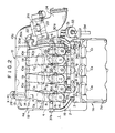
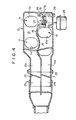
- the upper tank 13 and the lower tank 14 are curved upstream to extend forwardly toward upper and lower upstream tank portion 13a and 14a respectively and the upper and lower upstream tank portion 13a and 14a are connected with an upper throttle body 21 a and a lower throttle body 21 b respectively as shown in Figure 4.
- the throttle valves 22 and 23 for controlling the amount of intake air are provided in the upper upstream tank portion 13a and the lower upstream tank portion 14a respectively.
- the upper throttle body 21 a and the lower throttle body 21 b join into a main intake passage 24 upstream and an air cleaner (not shown) is provided upstream in the main intake passage 24.
- the surge tank 12 is supported by being connected with the cylinder head 4 by means of a connecting means 25.
- the upper tank 13 and the lower tank 14 are communicated with each other through a communicating passage 26 provided at the left end of the lower tank 14 as shown in Figures 3 and 4.
- the communication controlling valve 27 is provided in the communicating passage 26 for controllingthe area of the opening of the communicating passage 26. More specifically, the wall 15 is curved downwardly in the vicinity of the position at which the second upstream intake passage 11 a for the sixth cylinder C6 is connected with the upper tank 13 and the communicating passage 26 is bored in such downwardly curved portion of the wall 15.
- a shaft 27a of butterfly-type of the communication controlling valve 27 is disposed in the longitudinal direction of the vehicle body and the opening of the communicating passage 26 is controlled by rotating the communication controlling valve 27 by means of an actuator 28 in accordance with the engine r.p.m. so that the opening of the communicating passage 26 is increased as the engine r.p.m. is increased.
- a drain port 29 for discharging water produced by condensation and the like out of the surge tank 12 is provided at the bottom of the surge tank 12 and water in the lower tank 14 is discharged through said drain port 29 together with water produced in the upper tank 13 and led into the lower tank 14 through the communicating passage 26 when the communication controlling valve 27 is opened.
- the drain port 29 is communicated with the intake manifold 6 downstream of the surge tank 12.
- an exhaust gas recirculation - (hereinafter referred to as EGR) passage 30 for recirculating exhaust gases to decrease the amount of emmitted nitrogen oxide gas is provided in the intake system as shown in Figure 5 and 6.
- the EGR passage 30 extends through the EGR adaptor 31 and an outlet portion 30a to the flanges 16 and 17, and a downstream EGR passage 30b communicated with the EGR passage 30 and formed integrally with the upstream intake passage 10a is provided inside of the upstream intake passage 10a for the cylinder C1.
- the downstream EGR passage 30b is communicated with the upper upstream tank portion 13a through an opening 30c and with the lower upstream tank portion 14a through an opening 30d. Consequently, it is possible to recirculate uniform amount of the EGR gas to each cylinder.
- a fuel injector 36 for injecting fuel into the intake port 8 of the cylinders C1 to C6 is provided on the flanges 10c and 11 at the ends of the downstream intake passage 10b and 11 b.
- the injector 36 is connected with a fuel distributing pipe 37a for the front bank 1A and another fuel distributing pipe 37b for the rear bank 1 B and fuel is fed to the fuel injector therefrom.
- a bonnet 38 for covering the engine compartment is disposed above the engine 1 and extends forwardly and downwardly.
- the firing order of the six cylinder V-type engine is set as C1-C2-C3-C4-C5-C6 in this embodiment wherein the cylinders C1, C3 and C5 belong to the front bank 1A and the cylinders C2, C4 and C6 belong to the rear bank 1 B. Therefore, after a firing occurs in a cylinder connected to either the upper same tank 13 or the lower tank 14, a firing does not follow in a cylinder connected to the same surge tank 13 or 14. In other words, when a firing occurs in a cylinder connected to the upper tank 13, successive firing occurs in a cylinder connected to the lower tank 14. As a result, interference between the intake air of the respective cylinders does not occur in the surge tank 12.
- a negative pressure wave generated in each cylinder by opening and shutting the intake valve 9 in an intake step is transmitted to the upper tank 13 or the lower tank 14 through the independent intake passage 10 or 11.
- the phase of the negative pressure wave generated in the cylinders belonging to the front bank 1A is reverse to that in the cylinders belonging to the rear bank 1 B in this embodiment due to the firing order as described above. Accordingly, since the independent intake passages 10 and 11 for each cylinder have same length, the pressure wave transmitted to the upper tank 13 is shifted by a half wavelength relative to that transmitted to the lower tank 14.
- the power output of the engine can be remarkably increased by the inertia effect generated by the pressure waves reflected by the upper and lower tank 13 and 14. Further, the inertia effect and the harmonic resonance effect can be effectively utilized over a wider range of engine r.p.m. by controlling the volume effect of the upper and lower surge tank 13 and 14 by adjusting the opening of the communication controlling valve 27.
- each independent intake passage 10 and 11 is divided into two components, the upstream intake passage 10a, 11 a and the downstream intake passage 10b, 11 b. and the downstream intake passages 10b and 11 are connected with each other by the flanges 16 and 17, the flange 10c and 11 c of the downstream intake passages 10b and 11 b can be easily connected with the cylinders without interference from the upstream intake passages 10a and 11 a, and the fuel injectors 36 and the fuel distributing pipes 37 can be also easily connected with the cylinders.
- the upstream intake passages 10a and 11 a are formed integrally with the surge tank 12 and the connecting surface portion F connecting the upstream intake passage 10a, 11 a and the downstream intake passage 10b, 11 b is substantially horizontally arranged, the flanges 16 and 17 can be easily connected even at the boss portion 16a behind the upstream intake passage 10a by screwing the bolts 19.
- the curvature of the independent intake passages 10 and 11 can be made small, the pressure losses therethrough can be controlled to be small and sufficient amounts of intake air can be fed to the combustion chamber 7 under high r.p.m. condition.
- the intake system is not provided above the front bank 1 A, the clearance between the engine 1 and the hood 38 can be made sufficiently small.
- the intake system is provided above the rear bank 1 B, since the hood 38 extends backwardly and upwardly and the clearance between the rear bank 1 B and the hood 38 is relatively large, the intake system can be easily arranged in the space between the rear bank 1 B and the hood 38 with the intake passages having sufficient length.
- the communicating passage 26 and the communication controlling valve 27 can be arranged in thus obtained free space on the left side of the lower tank 14 and the size of the induction system can be reduced.
- the present invention is applied to a laterally disposed V-type engine, the present invention can be applied to other types of V-type engines similarly.
- the upstream intake passages 11 a may be arranged above other upstream intake passages 10a in order to reduce the width of the induction system.
- each upstream intake passage 11 a extends substantially horizontally from the upper surge tank 13 in the above described embodiment, it may be arranged to extend upwardly from the upper surge tank 13 in the vicinity of the upper surge tank 13 so as to make the length of each independent intake passage 10 equal to that of each of another independent intake passage 11 to minimize the difference in the the pressure losses between the independent intake passages 10 and 11.
Landscapes
- Engineering & Computer Science (AREA)
- Chemical & Material Sciences (AREA)
- Combustion & Propulsion (AREA)
- Mechanical Engineering (AREA)
- General Engineering & Computer Science (AREA)
- Manufacturing & Machinery (AREA)
- Characterised By The Charging Evacuation (AREA)
Applications Claiming Priority (6)
| Application Number | Priority Date | Filing Date | Title |
|---|---|---|---|
| JP60221650A JPS6291621A (ja) | 1985-10-04 | 1985-10-04 | V型エンジンの吸気装置 |
| JP221650/85 | 1985-10-04 | ||
| JP434/86 | 1986-01-06 | ||
| JP61000435A JPH0678731B2 (ja) | 1986-01-06 | 1986-01-06 | V型エンジンの吸気装置 |
| JP435/86 | 1986-01-06 | ||
| JP61000434A JPH0730696B2 (ja) | 1986-01-06 | 1986-01-06 | V型エンジンの吸気装置 |
Publications (3)
| Publication Number | Publication Date |
|---|---|
| EP0223378A2 true EP0223378A2 (de) | 1987-05-27 |
| EP0223378A3 EP0223378A3 (en) | 1988-04-27 |
| EP0223378B1 EP0223378B1 (de) | 1991-01-02 |
Family
ID=27274465
Family Applications (1)
| Application Number | Title | Priority Date | Filing Date |
|---|---|---|---|
| EP86307662A Expired - Lifetime EP0223378B1 (de) | 1985-10-04 | 1986-10-03 | Einlassvorrichtung für V-Brennkraftmaschinen |
Country Status (4)
| Country | Link |
|---|---|
| US (1) | US4708097A (de) |
| EP (1) | EP0223378B1 (de) |
| KR (1) | KR900000143B1 (de) |
| DE (1) | DE3676452D1 (de) |
Cited By (15)
| Publication number | Priority date | Publication date | Assignee | Title |
|---|---|---|---|---|
| EP0270784A3 (en) * | 1986-12-06 | 1988-11-02 | Dr.Ing.H.C. F. Porsche Aktiengesellschaft | Intake arrangement for a multi-cylinder internal combustion engine |
| EP0450530A1 (de) * | 1990-03-31 | 1991-10-09 | Mazda Motor Corporation | Einlassanordnung für V-Brennkraftmaschine |
| EP0471886A1 (de) * | 1989-02-28 | 1992-02-26 | Yamaha Hatsudoki Kabushiki Kaisha | Entlüftungsanlage für eine Kraftwagenbrennkraftmaschine |
| EP0483672A1 (de) * | 1990-10-29 | 1992-05-06 | Mazda Motor Corporation | Motorlufteinlasssystem |
| WO1993000505A3 (en) * | 1991-06-24 | 1993-03-18 | Lotus Car | Intake manifold for a multi-cylinder internal combustion engine |
| EP0565410A1 (de) * | 1992-04-09 | 1993-10-13 | Automobiles Peugeot | Integrierte Rampenvorrichtung für die Abgasrückführung einer Brennkraftmaschine |
| EP0644326A1 (de) * | 1993-09-17 | 1995-03-22 | Hitachi, Ltd. | Einlassvorrichtung für Brennkraftmaschine |
| FR2712636A1 (fr) * | 1993-11-17 | 1995-05-24 | Orbey Plastiques Ind | Procédé de fabrication d'un répartiteur d'admission et répartiteur obtenu au moyen dudit procédé. |
| EP0688943A1 (de) * | 1994-05-19 | 1995-12-27 | Dr.Ing.h.c. F. Porsche Aktiengesellschaft | Luftansaugeanlage einer mehrzylindrigen Brennkraftmaschine |
| EP0857869A1 (de) * | 1997-01-21 | 1998-08-12 | Daimler-Benz Aktiengesellschaft | Halterung einer Abgasrückführleitung am Motorgehäuse einer Brennkraftmaschine |
| WO2008101977A1 (de) * | 2007-02-23 | 2008-08-28 | Mahle International Gmbh | Brennkraftmaschinensystem |
| EP2031197A1 (de) * | 2007-08-31 | 2009-03-04 | Honda Motor Co., Ltd | V-Motor für Fahrzeug |
| WO2010007024A1 (de) | 2008-07-18 | 2010-01-21 | Mahle International Gmbh | Frischluftanlage |
| DE102009000035B4 (de) * | 2008-01-08 | 2011-06-30 | Toyota Jidosha Kabushiki Kaisha, Aichi-ken | Aufbau zum Einleiten von Gas in eine Einlassluft |
| CN104929825A (zh) * | 2014-03-19 | 2015-09-23 | 雅马哈发动机株式会社 | 骑乘型车辆 |
Families Citing this family (25)
| Publication number | Priority date | Publication date | Assignee | Title |
|---|---|---|---|---|
| US4848280A (en) * | 1987-01-09 | 1989-07-18 | Mazda Motor Corporation | Intake apparatus for internal combustion engine |
| US4794886A (en) * | 1987-04-01 | 1989-01-03 | Toyota Jidosha Kabushiki Kaisha | Intake device of an internal combustion engine |
| KR920001169B1 (ko) * | 1987-09-08 | 1992-02-06 | 마쓰다 가부시끼가이샤 | "v"형 엔진의 흡기장치 |
| JPH07113327B2 (ja) * | 1987-10-01 | 1995-12-06 | マツダ株式会社 | エンジンの吸気装置 |
| JPH01106922A (ja) * | 1987-10-19 | 1989-04-24 | Mazda Motor Corp | V型エンジンの吸気装置 |
| JPH045725Y2 (de) * | 1987-12-17 | 1992-02-18 | ||
| JPH07691Y2 (ja) * | 1988-07-12 | 1995-01-11 | 日産自動車株式会社 | 内燃機関のegrバルブ取付構造 |
| KR940000129B1 (ko) * | 1988-07-29 | 1994-01-07 | 마쯔다 가부시기가이샤 | V형엔진의 흡기장치 |
| JP2725034B2 (ja) * | 1988-10-31 | 1998-03-09 | マツダ株式会社 | エンジンの吸気装置 |
| JPH02215961A (ja) * | 1989-02-17 | 1990-08-28 | Nissan Motor Co Ltd | エンジンの吸気マニホールド装置 |
| JP2732647B2 (ja) * | 1989-02-22 | 1998-03-30 | ヤマハ発動機株式会社 | 車両用エンジンの吸気装置 |
| US5056472A (en) * | 1989-06-06 | 1991-10-15 | Mazda Motor Corporation | 4-cycle 12-cylinder engine |
| JP2518930B2 (ja) * | 1989-07-24 | 1996-07-31 | 日産自動車株式会社 | 内燃機関の吸気装置 |
| DE4125249C2 (de) * | 1991-07-31 | 1994-03-03 | Freudenberg Carl Fa | Elastische Befestigungsvorrichtung zur Verbindung eines Ansaugrohres mit einer Verbrennungskraftmaschine |
| US5263440A (en) * | 1993-04-05 | 1993-11-23 | Ford Motor Company | Intake manifold for internal combustion engine |
| JP3498334B2 (ja) * | 1993-11-08 | 2004-02-16 | 株式会社日立製作所 | 内燃機関の吸気装置 |
| DE4432349A1 (de) * | 1994-09-12 | 1996-03-14 | Bayerische Motoren Werke Ag | Schaltklappe für einen Brennkraftmaschinen-Luftsammler |
| DE19521169A1 (de) * | 1995-06-10 | 1996-12-12 | Bosch Gmbh Robert | Einrichtung zur Einstellung der Rohrlänge von Saugrohren und Verfahren zu deren Herstellung |
| JP2864365B2 (ja) * | 1996-04-16 | 1999-03-03 | 本田技研工業株式会社 | エンジンの吸気装置 |
| JP2002054521A (ja) * | 2000-08-11 | 2002-02-20 | Honda Motor Co Ltd | エンジンの燃料ポンプ取付構造 |
| DE60201942T2 (de) * | 2001-05-15 | 2005-11-24 | Keihin Corp. | Einlasssystem für eine mehrzylindrige Brennkraftmaschine |
| JP3820924B2 (ja) * | 2001-06-20 | 2006-09-13 | トヨタ自動車株式会社 | 内燃機関の可変吸気装置及びその製造方法 |
| JP4301074B2 (ja) * | 2004-05-12 | 2009-07-22 | トヨタ自動車株式会社 | 多気筒エンジンの吸気装置 |
| AT500541B1 (de) * | 2005-10-20 | 2007-05-15 | Avl List Gmbh | Brennkraftmaschine |
| GB2447035B (en) * | 2007-03-01 | 2009-01-28 | Lotus Car | An intake plenum arrangement for a multi-cylinder internal combustion engine |
Family Cites Families (11)
| Publication number | Priority date | Publication date | Assignee | Title |
|---|---|---|---|---|
| US3303832A (en) * | 1967-02-14 | High output engines | ||
| US2909165A (en) * | 1956-09-10 | 1959-10-20 | Gen Motors Corp | Fuel injection system |
| US2947294A (en) * | 1957-06-10 | 1960-08-02 | Gen Motors Corp | Induction system |
| US2845912A (en) * | 1957-09-06 | 1958-08-05 | Gen Motors Corp | Induction system |
| JPS56113042A (en) * | 1980-02-08 | 1981-09-05 | Yamaha Motor Co Ltd | Engine for vehicle |
| JPS57110765A (en) * | 1980-12-27 | 1982-07-09 | Yamaha Motor Co Ltd | Intake unit for multiple intake valve type engine |
| US4440120A (en) * | 1982-05-24 | 1984-04-03 | General Motors Corporation | Compact ram tube engine air intake manifold |
| JPS5977063A (ja) * | 1982-10-25 | 1984-05-02 | Honda Motor Co Ltd | 内燃機関のヘツドカバ−取付装置 |
| JPS59115460A (ja) * | 1982-12-22 | 1984-07-03 | Honda Motor Co Ltd | V型内燃機関の吸気マニホルド構造 |
| JPS6060252A (ja) * | 1983-09-13 | 1985-04-06 | Mazda Motor Corp | V型エンジンの排気ガス還流装置 |
| US4649871A (en) * | 1984-03-22 | 1987-03-17 | Mazda Motor Corporation | Intake system for V-type engine |
-
1986
- 1986-09-24 KR KR1019860007970A patent/KR900000143B1/ko not_active Expired
- 1986-10-02 US US06/914,662 patent/US4708097A/en not_active Expired - Lifetime
- 1986-10-03 EP EP86307662A patent/EP0223378B1/de not_active Expired - Lifetime
- 1986-10-03 DE DE8686307662T patent/DE3676452D1/de not_active Expired - Fee Related
Cited By (24)
| Publication number | Priority date | Publication date | Assignee | Title |
|---|---|---|---|---|
| EP0270784A3 (en) * | 1986-12-06 | 1988-11-02 | Dr.Ing.H.C. F. Porsche Aktiengesellschaft | Intake arrangement for a multi-cylinder internal combustion engine |
| US4829942A (en) * | 1986-12-06 | 1989-05-16 | Dr. Ing. H.C.F. Porsche Aktiengesellschaft | Intake system for a multi-cylinder internal-combustion engine |
| EP0471886A1 (de) * | 1989-02-28 | 1992-02-26 | Yamaha Hatsudoki Kabushiki Kaisha | Entlüftungsanlage für eine Kraftwagenbrennkraftmaschine |
| EP0450530A1 (de) * | 1990-03-31 | 1991-10-09 | Mazda Motor Corporation | Einlassanordnung für V-Brennkraftmaschine |
| EP0483672A1 (de) * | 1990-10-29 | 1992-05-06 | Mazda Motor Corporation | Motorlufteinlasssystem |
| US5168838A (en) * | 1990-10-29 | 1992-12-08 | Mazda Motor Corporation | Engine induction system |
| WO1993000505A3 (en) * | 1991-06-24 | 1993-03-18 | Lotus Car | Intake manifold for a multi-cylinder internal combustion engine |
| EP0565410A1 (de) * | 1992-04-09 | 1993-10-13 | Automobiles Peugeot | Integrierte Rampenvorrichtung für die Abgasrückführung einer Brennkraftmaschine |
| FR2689936A1 (fr) * | 1992-04-09 | 1993-10-15 | Peugeot | Dispositif à rampe intégrée pour le recyclage des gaz d'échappement d'un moteur à combustion interne. |
| EP0644326A1 (de) * | 1993-09-17 | 1995-03-22 | Hitachi, Ltd. | Einlassvorrichtung für Brennkraftmaschine |
| FR2712636A1 (fr) * | 1993-11-17 | 1995-05-24 | Orbey Plastiques Ind | Procédé de fabrication d'un répartiteur d'admission et répartiteur obtenu au moyen dudit procédé. |
| US5595150A (en) * | 1994-05-19 | 1997-01-21 | Dr. Ing H.C.F. Porsche Ag | Air intake system with a throttle valve for a multi-cylinder internal-combustion engine |
| EP0688943A1 (de) * | 1994-05-19 | 1995-12-27 | Dr.Ing.h.c. F. Porsche Aktiengesellschaft | Luftansaugeanlage einer mehrzylindrigen Brennkraftmaschine |
| EP0857869A1 (de) * | 1997-01-21 | 1998-08-12 | Daimler-Benz Aktiengesellschaft | Halterung einer Abgasrückführleitung am Motorgehäuse einer Brennkraftmaschine |
| US5988148A (en) * | 1997-01-21 | 1999-11-23 | Daimler Chrysler Ag | Mounting arrangement for an exhaust gas recirculation pipe on an internal combustion engine |
| WO2008101977A1 (de) * | 2007-02-23 | 2008-08-28 | Mahle International Gmbh | Brennkraftmaschinensystem |
| US8176902B2 (en) | 2007-02-23 | 2012-05-15 | Mahle International Gmbh | Internal combustion engine system |
| EP2031197A1 (de) * | 2007-08-31 | 2009-03-04 | Honda Motor Co., Ltd | V-Motor für Fahrzeug |
| DE102009000035B4 (de) * | 2008-01-08 | 2011-06-30 | Toyota Jidosha Kabushiki Kaisha, Aichi-ken | Aufbau zum Einleiten von Gas in eine Einlassluft |
| US8051843B2 (en) | 2008-01-08 | 2011-11-08 | Toyota Jidosha Kabushiki Kaisha | Structure for introducing gas into intake air |
| WO2010007024A1 (de) | 2008-07-18 | 2010-01-21 | Mahle International Gmbh | Frischluftanlage |
| US8991366B2 (en) | 2008-07-18 | 2015-03-31 | Mahle International Gmbh | Fresh air system |
| CN104929825A (zh) * | 2014-03-19 | 2015-09-23 | 雅马哈发动机株式会社 | 骑乘型车辆 |
| EP2921689A1 (de) * | 2014-03-19 | 2015-09-23 | Yamaha Hatsudoki Kabushiki Kaisha | Sattel- oder Grätschsitzfahrzeug |
Also Published As
| Publication number | Publication date |
|---|---|
| DE3676452D1 (de) | 1991-02-07 |
| KR900000143B1 (ko) | 1990-01-20 |
| KR870004225A (ko) | 1987-05-08 |
| EP0223378B1 (de) | 1991-01-02 |
| US4708097A (en) | 1987-11-24 |
| EP0223378A3 (en) | 1988-04-27 |
Similar Documents
| Publication | Publication Date | Title |
|---|---|---|
| EP0223378B1 (de) | Einlassvorrichtung für V-Brennkraftmaschinen | |
| US4615324A (en) | Exhaust gas recirculation system for a V-type engine | |
| US6039029A (en) | Induction system for fuel injected engine | |
| US4262639A (en) | Intake system of a multi-cylinder internal combustion engine | |
| US4766853A (en) | Intake passage for multi-cylinder engine | |
| US7556010B2 (en) | Multicylinder internal combustion engine with resonator | |
| US6062024A (en) | Manifold for a turbo-charged internal combustion engine | |
| EP0352820B1 (de) | Einlassanordnung für Brennkraftmaschine mit V-förmig angeordneten Zylinderreihen | |
| US4878460A (en) | Intake system for V-type internal combustion engine | |
| US5515822A (en) | Intake system | |
| EP0370515A2 (de) | Lufteinlasssystem für Mehrzylinderbrennkraftmaschine der V-Bauart | |
| EP0499268B1 (de) | Vielfachventilbrennkraftmaschine | |
| US4919087A (en) | Intake system for V-type vehicle engine | |
| US4261316A (en) | Intake system of a multi-cylinder internal combustion engine | |
| US6526933B2 (en) | Multi-cylinder internal combustion engine | |
| US5127370A (en) | Induction system for V type engine | |
| US5787851A (en) | Intake control system | |
| US5031598A (en) | Intake system for multi-cylinder engine with supercharger | |
| JPH0428888B2 (de) | ||
| US7150256B2 (en) | Intake device of multi-cylinder engine | |
| CN110431299A (zh) | 多气缸发动机的吸气通路构造 | |
| US6622687B2 (en) | Intake apparatus of multi-cylinder internal combustion engine | |
| US5123383A (en) | Intake system for internal combustion engine | |
| EP0694690B1 (de) | Luftansaugsystem einer Brennkraftmaschine in V-Bauart | |
| JPH0730696B2 (ja) | V型エンジンの吸気装置 |
Legal Events
| Date | Code | Title | Description |
|---|---|---|---|
| PUAI | Public reference made under article 153(3) epc to a published international application that has entered the european phase |
Free format text: ORIGINAL CODE: 0009012 |
|
| 17P | Request for examination filed |
Effective date: 19861013 |
|
| AK | Designated contracting states |
Kind code of ref document: A2 Designated state(s): DE FR GB |
|
| PUAL | Search report despatched |
Free format text: ORIGINAL CODE: 0009013 |
|
| AK | Designated contracting states |
Kind code of ref document: A3 Designated state(s): DE FR GB |
|
| 17Q | First examination report despatched |
Effective date: 19880907 |
|
| GRAA | (expected) grant |
Free format text: ORIGINAL CODE: 0009210 |
|
| AK | Designated contracting states |
Kind code of ref document: B1 Designated state(s): DE FR GB |
|
| REF | Corresponds to: |
Ref document number: 3676452 Country of ref document: DE Date of ref document: 19910207 |
|
| ET | Fr: translation filed | ||
| PLBE | No opposition filed within time limit |
Free format text: ORIGINAL CODE: 0009261 |
|
| STAA | Information on the status of an ep patent application or granted ep patent |
Free format text: STATUS: NO OPPOSITION FILED WITHIN TIME LIMIT |
|
| 26N | No opposition filed | ||
| PGFP | Annual fee paid to national office [announced via postgrant information from national office to epo] |
Ref country code: GB Payment date: 20011003 Year of fee payment: 16 |
|
| PGFP | Annual fee paid to national office [announced via postgrant information from national office to epo] |
Ref country code: FR Payment date: 20011010 Year of fee payment: 16 |
|
| REG | Reference to a national code |
Ref country code: GB Ref legal event code: IF02 |
|
| PG25 | Lapsed in a contracting state [announced via postgrant information from national office to epo] |
Ref country code: GB Free format text: LAPSE BECAUSE OF NON-PAYMENT OF DUE FEES Effective date: 20021003 |
|
| GBPC | Gb: european patent ceased through non-payment of renewal fee |
Effective date: 20021003 |
|
| PG25 | Lapsed in a contracting state [announced via postgrant information from national office to epo] |
Ref country code: FR Free format text: LAPSE BECAUSE OF NON-PAYMENT OF DUE FEES Effective date: 20030630 |
|
| REG | Reference to a national code |
Ref country code: FR Ref legal event code: ST |
|
| PGFP | Annual fee paid to national office [announced via postgrant information from national office to epo] |
Ref country code: DE Payment date: 20040930 Year of fee payment: 19 |
|
| PG25 | Lapsed in a contracting state [announced via postgrant information from national office to epo] |
Ref country code: DE Free format text: LAPSE BECAUSE OF NON-PAYMENT OF DUE FEES Effective date: 20060503 |