EP0223436B1 - Bild-in-Bild-Fernsehempfänger - Google Patents
Bild-in-Bild-Fernsehempfänger Download PDFInfo
- Publication number
- EP0223436B1 EP0223436B1 EP86308268A EP86308268A EP0223436B1 EP 0223436 B1 EP0223436 B1 EP 0223436B1 EP 86308268 A EP86308268 A EP 86308268A EP 86308268 A EP86308268 A EP 86308268A EP 0223436 B1 EP0223436 B1 EP 0223436B1
- Authority
- EP
- European Patent Office
- Prior art keywords
- signal
- subpicture
- picture
- main picture
- digital
- Prior art date
- Legal status (The legal status is an assumption and is not a legal conclusion. Google has not performed a legal analysis and makes no representation as to the accuracy of the status listed.)
- Expired - Lifetime
Links
Images

Classifications
-
- H—ELECTRICITY
- H04—ELECTRIC COMMUNICATION TECHNIQUE
- H04N—PICTORIAL COMMUNICATION, e.g. TELEVISION
- H04N5/00—Details of television systems
- H04N5/44—Receiver circuitry for the reception of television signals according to analogue transmission standards
- H04N5/445—Receiver circuitry for the reception of television signals according to analogue transmission standards for displaying additional information
- H04N5/45—Picture in picture, e.g. displaying simultaneously another television channel in a region of the screen
-
- H—ELECTRICITY
- H04—ELECTRIC COMMUNICATION TECHNIQUE
- H04N—PICTORIAL COMMUNICATION, e.g. TELEVISION
- H04N5/00—Details of television systems
- H04N5/222—Studio circuitry; Studio devices; Studio equipment
- H04N5/262—Studio circuits, e.g. for mixing, switching-over, change of character of image, other special effects ; Cameras specially adapted for the electronic generation of special effects
- H04N5/265—Mixing
Definitions
- This invention relates to picture-in-picture television receivers for reproducing two different pictures simultaneously on a common display screen (such as a display screen of a cathode ray tube), and to methods of reproducing two different pictures simultaneously on a common display screen of a picture-in-picture television receiver.
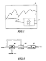
- Figure 1 of the accompanying drawings shows a display screen of a previously proposed picture-in-picture (P in P) television receiver on which an A-channel picture and a B-channel picture are simultaneously displayed.
- the B-channel picture (hereinafter referred to as a "subpicture”) is inserted at a predetermined area of the A-channel picture (hereinafter referred to as a "main picture”) by reducing (compressing) both the lateral and vertical dimensions of the subpicture to 1/3, for instance, of those of the main picture.
- the subpicture signal is first subjected to analog to digital (A-D) conversion, and the horizontal and vertical scanning lines then are extracted in a ratio of 1 out of 3 before being written in a picture memory.
- the subpicture signal is written in the memory, in response to a clock signal synchronised with a synchronising signal of the subpicture signal, while the subpicture signal is read out from the memory, at a speed which is three times higher than that employed in writing the signal, in response to a clock signal synchronised with a synchronising signal of the main picture signal.
- a subpicture signal is converted from an analog signal to a digital signal, stored in a memory via a write process circuit, read from the memory, and converted from a digital signal to an analog signal.
- successive portions of the subpicture signal each composed of a plurality of bits of the digital signal arranged in series, are processed.
- the time during which variation in signal data becomes stable is different among the bit of the signal making up the plurality, there is a problem in that unstable data durations or intervals occur before the data represented by all of the bits of each plurality becomes stable.
- US Patent US-A-4 367 484 discloses a picture-in-picture television receiver according to the precharacterising part of claim 1 of this specification and a method of picture reproduction according to the precharacterising part of claim 4 of this specification.
- a picture-in-picture television receiver for reproducing two different pictures simultaneously on a common display screen such that one of said pictures (“subpicture”) is inserted in a predetermined area of the other of said pictures (“main picture”)
- the receiver comprising: memory means; write processing circuit means for writing a subpicture signal representing the subpicture into the memory means under the control of a synchronising signal of the subpicture signal; read processing circuit means for reading the signal stored in the memory means under the control of a synchronising signal of a main picture signal representing the main picture; and means for combining the read signal with the main picture signal to produce a signal for display;
- the receiver being characterised in that: an analog-to-digital converter means is provided for converting an analog subpicture signal into a digital subpicture signal; and the write processing circuit means comprises: first latch circuit means for latching the digital subpicture signal in response to a subpicture clock signal which is in synchronism with the subpicture synchronising signal; second latch circuit means for
- a preferred embodiment of the present invention described in detail hereinbelow provides a picture-in-picture television receiver which can eliminate the above-mentioned unstable data durations or intervals and can stably convert the sampling frequency of the subpicture signal to that of the main picture signal.
- one latch circuit is synchronised with a subpicture and the other latch circuit is synchronised with a main picture, whereby it is possible to eliminate the subpicture data signal being latched to the main picture side during the unstable data durations or intervals, so that the conversion of the sampling frequency can be effected stably from the subpicture side to the main picture side.
- Figure 1 shows a screen of a picture-in-picture television receiver
- Figure 2 is a schematic block diagram showing an exemplary circuit of a picture-in-picture television receiver in which the present invention can be embodied
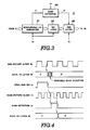
- Figure 3 is a schematic block diagram showing a write processing circuit incorporated in the circuit shown in Figure 1 to form a picture-in-picture television receiver that is a preferred embodiment of the invention
- Figure 4 is a timing chart for the write processing circuit shown in Figure 3
- Figure 5 is a block diagram showing an embodiment of a picture quality improvement circuit which can be connected to the write processing circuit shown in Figure 3.
- Figure 2 shows an exemplary circuit of a picture-in-picture television receiver, the circuit comprising an antenna (aerial) 1, a tuning circuit 2, an intermediate frequency amplifier and video detecting circuit 3, and a composite video signal input terminal 4 to which a video signal, for example a playback signal from a video tape recorder (VTR), can be supplied.
- a main-sub switching circuit 5 selects one of a video signal from the circuit 3 and a video signal from the terminal 4 as a main picture and the other as a subpicture.
- the main picture video signal obtained from the switching circuit 5 is applied to a Y/C processing and synchronising signal processing circuit 6 which provides a main picture video signal S M , a main picture vertical synchronising signal V M , and a main picture horizontal synchronising signal H M .
- the subpicture signal obtained from the switching circuit 5 is applied to a Y/C processing and synchronising signal processing circuit 7 to provide a subpicture video signal S S , a subpicture vertical synchronising signal V S , and a subpicture horizontal synchronising signal H S .
- the subpicture video signal S S is applied to an analog to digital (A-D) converter 8 which converts it into a digital signal.
- the digital signal is written in an image memory 10 through a write processing circuit 9. If the subpicture is reduced in size in both the vertical and horizontal directions to 1/3 of the size of the main picture, the horizontal and vertical scanning lines are extracted by the write processing circuit 9 in a ratio of 1 out of 3 and then written in the memory 10. By virtue of this processing operation, effective picture information made up of 64 scanning lines per one field, for instance, is written in the memory 10. Further, in addition to the above-mentioned processing operation, the write processing circuit 9 converts a sampling frequency in a manner described hereinbelow with reference to Figure 3.
- a subpicture clock oscillator or generator 11 generates a clock pulse signal having a frequency ("write frequency") fw in synchronism with the subpicture vertical and horizontal synchronising signals V S and H S .
- a write address generator 12 On the basis of the clock pulse signal having the frequency fw, a write address generator 12 generates write address signals WA representing write addresses from "0" to "2047".
- the write address signals WA are supplied to the memory 10 via a memory controller or control circuit 13.
- Data read from the memory 10 is applied to a digital-to-analog (D-A) converter 15 via a read processing circuit 14 to convert the digital subpicture signal to the original analog video signal S S .
- D-A digital-to-analog
- a main picture clock oscillator or generator 16 generates a clock pulse signal having a frequency ("read frequency") f R in synchronism with the main picture vertical and horizontal synchronising signals V M and H M .
- a read address generator 17 On the basis of these signals, a read address generator 17 generates read address signals RA representing read addresses from "0" to "2047".
- the read address signals RA are supplied to the memory 10 via the memory control circuit 13.
- the above-mentioned reading operation is executed at a speed three times higher than that employed for writing. That is, information of one scanning line H is speedily read during a period of 1/3H.
- the write frequency fw is selected to be 4/3fsc and the read frequency f R is selected to be 2fsc, for instance, where fsc denotes a subcarrier frequency.
- the read frequency f R is selected to be 3/2 times (and not three times) the write frequency fw. This is because the A-D converter 8 converts a luminance signal and a colour difference signal from the circuit 7 in a time divisional manner as is well known in the art.
- the subpicture video signal S S obtained by the D-A converter 15 is applied to a composing circuit 18 together with the main picture video signal S M obtained by the processing circuit 6.
- the composing circuit 18 is controlled by a switching signal S C applied from a control circuit 19. Therefore, it is possible for the composing circuit 18 to provide a composite signal S M + S S , in which the signal S S is inserted into a predetermined area of the signal S M , the composite signal being supplied to a picture tube 20.
- the subpicture B reduced in size by a factor of 1/3 both vertically and horizontally, is reproduced at a predetermined area of the main picture A, as shown in Figure 1, on the picture tube 20.
- a switch 19a is provided for the control circuit 19. When the switch 19a is manually turned on, the subpicture B can be erased.
- items of data each comprising 5 bits arranged in series, for instance, are inputted from the A-D converter 8 to a series to parallel converter 91.
- the converter 91 for instance, six 5-bit memory circuits are connected in series.
- the converter 91 and a succeeding stage in the form of a 30-bit latch circuit 92 are activated in response to the subpicture clock signal having the frequency fw, and a further succeeding stage in the form of a latch circuit 93 is activated in response to the main picture clock signal having the frequency f R .
- 30 bits of data X, Y are sequentially inputted to the latch circuit 92 in a ratio of one out of six pulses of the subpicture clock signal.
- the time during which the data becomes stable without variation is different for each bit of the 30 bits of data, so that an unstable data duration or interval occurs until all of the 30 bits become stable.
- a conversion-end signal a1 is outputted by the converter 91.
- the trailing edge of the signal a1 is detected by an edge detector or detection circuit 94 as an edge detection signal a2 in synchronism with the main picture clock signal.
- the succeeding stage latch circuit 93 is activated so as to latch the data of the latch circuit 92. Since the above-mentioned unstable data duration or interval is usually shorter than one period of the main picture clock signal, the latch circuit 93 never fetches the data from the latch circuit 92 within the unstable data duration or interval.
- the memory 10 can be operated in synchronism with the main picture clock signal having the frequency f R during both the writing and reading periods, so that any data can be handled without the influence of the unstable data durations or intervals mentioned above.
- the operation of fetching data from the latch circuit 92 to the latch circuit 93 can be selected at any point in time within six periods of the main picture clock signal. Further, the output of the latch circuit 93 is written in the memory 10 after a necessary processing operation, in which one scanning line is extracted from three scanning lines, has been completed.
- Figure 5 shows an embodiment of a picture quality improvement circuit for solving at least partially the above-mentioned problem.
- the picture quality improving circuit is connected between the A-D converter 8 and the write processing circuit 9.
- a scanning line is added to a previous scanning line, and a resultant added or addition output is averaged by multiplication by 1/2. For instance, in one field of the subpicture signal, the 1st scanning line is discarded, the 2nd and 3rd scanning lines are added together, and the addition output thereof is divided by 2.
- the speed of operation of the line memory 95 since only the writing and reading operations are performed alternately in the line memory 95, it is sufficient for the speed of operation of the line memory 95 to correspond to the frequency fw of the subpicture clock signal. Therefore, it is possible to use a low-priced low-speed line memory 95.
Landscapes
- Engineering & Computer Science (AREA)
- Multimedia (AREA)
- Signal Processing (AREA)
- Studio Circuits (AREA)
- Television Signal Processing For Recording (AREA)
Claims (6)
- Bild-in-Bild-Fernsehempfänger zur simultanen Wiedergabe zweier verschiedener Fernsehbilder auf einem gemeinsamen Bildschirm, wobei eines dieser Bilder (Unterbild) in einem vorbestimmten Bereich des anderen Bildes (Hauptbild) eingesetzt ist, mit
einer Speicheranordnung (10),
einer Schreib-Prozessor-Schaltungsanordnung (9) zum Einschreiben eines das Unterbild repräsentierenden Unterbild-Signals in die Speicheranordnung (10) unter dem Steuereinfluß eines Synchronisiersignals des Unterbild-Signals,
einer Lese-Prozessor-Schaltungsanordnung (14) zum Auslesen des in der Speicheranordnung (10) gespeicherten Signals unter dem Steuereinfluß eines Synchronisiersignals eines das Hauptbild repräsentierenden Hauptbild-Signals, und
einer Einrichtung (18) zum Kombinieren des ausgelesenen Signals mit dem Hauptbild-Signal zur Erzeugung eines Signale für die Anzeige,
dadurch gekennzeichnet,
daß eine Analog/Digital-Wandlereinrichtung (8) zum Umwandeln eines analogen Unterbild-Signals in ein digitales Unterbild-Signal vorgesehen ist, und
daß die Schreib-Prozessor-Schaltungsanordnung (9) aufweist:- eine erste Halte-Schaltung (92) zum Halten des digitalen Unterbild-Signals in Abhängigkeit von einem Unterbild-Taktsignal (fw), das mit dem Unterbild-Synchronisiersignal synchronisiert ist,- eine zweite Halte-Schaltung (93) zum Halten des Ausgangssignal der ersten Halte-Schaltung (92) in Abhängigkeit von einem Hauptbild-Taktsignal (fR), des mit dem Hauptbild-Synchronisiersignal synchronisiert ist, wobei die zweite Halte-Schaltung (93) mit der Speicheranordnung (10) verbunden ist, so daß das Ausgangssignal der zweiten Halte-Schaltung (93) das in die Speicheranordnung (10) eingeschriebene Unterbild-Signal darstellt,- eine zwischen der Analog/Digital-Wandlereinrichtung (8) und der ersten Halte-Schaltung (92) angeordnete Serien/Parallel-Wandlereinrichtung (91) zur Aufnahme einer vorbestimmten Anzahl von Bits des digitalen Unterbild-Signals in Abhängigkeit von dem Unterbild-Taktsignal (fw), wobei die Serien/Parallel-Wandlereinrichtung (91) bewirkt, daß ein Umwandlungs-Endesignal (a1) ausgegeben wird, wenn die Serien/Parallel-Wandlung für die gesamte vorbestimmte Anzahl von Bits durchgeführt ist, und- einen Flankendetektor (94), der die Vorderflanke des Umwandlungs-Endesignal (a1) ermittelt und in Abhängigkeit hiervon die zweite Halte-Schaltung (92) nur denn zum Halten des Ausgangssignals der ersten Halte-Schaltung (91) veranlaßt, wenn nach der Ermittlung der Vorderflanke des Umwandlungs-Endesignals (a1) durch den Flankendetektor (94) eine vorbestimmte Anzahl von Perioden des Hauptbild-Taktsignals (fR) vergangen ist. - Bild-in-Bild-Fernsehempfänger nach Anspruch 1, bei dem die vorbestimmte Anzahl von Perioden des Hauptbild-Taktsignals (fR) gleich eins ist.
- Bild-in-Bild-Fernsehempfänger nach Anspruch 1 oder 2, mit einer zwischen der Analog/Digital-Wandlereinrichtung (8) und der Serien/Parallel-Wandlereinrichtung (91) angeordneten Schaltungsanordnung zur Verbesserung der Bildqualität, die folgende Teile aufweist:(a) einen Zeilenspeicher (95) zur Speicherung vorbestimmter Zeilen des digitalen Unterbild-Signals in Abhängigkeit von dem Unterbild-Taktsignal (fw),(b) eine Addiereinrichtung (96) zum Addieren einer aus dem Zeilenspeicher (95) ausgelesenen Unterbild-Signalzeile zu einer nachfolgenden Unterbild-Signalzeile und(c) eine 1/2-Multipliziereinrichtung (97) zur Mittelwertbildung der addierten Unterbildzeilen.
- Verfahren zum Wiedergeben zweier verschiedener Fernsehbilder auf einem gemeinsamen Bildschirm, wobei eines dieser Bilder (Unterbild) in einem vorbestimmten Bereich des anderen Bildes (Heuptbild) eingefügt ist,
mit den Verfahrensschritten:
Einschreiben eines das Unterbild repräsentierenden Unterbild-Signals in eine Speicheranordnung (10) unter dem Steuereinfluß eines Synchronisiersignals des Unterbild-Signals,
Auslesen des in der Speicheranordnung (10) gespeicherten Signals unter dem Steuereinfluß eines Synchronisiersignals eines das Hauptbild repräsentierenden Hauptbild-Signals, und
Kombinieren (18) des ausgelesenen Signals mit dem Hauptbild-Signal zur Erzeugung eines Signals für die Anzeige,
dadurch gekennzeichnet,
daß ein analoges Unterbild-Signal in ein digitales Unterbild-Signal umgewandelt wird (8) und
daß der Verfahrensschritt des Schreibens (9) folgende Funktionen umfaßt:- Halten (92) des digitalen Unterbild-Signals in Abhängigkeit von einem Unterbild-Taktsignal (fw), das mit dem Unterbild-Synchronisiersignal synchronisiert ist,- Halten (93) des aus dem ersten Haltsvorgang resultierenden Ausgangssignals in Abhängigkeit von einem Hauptbild-Taktsignal (fR), das mit dem Hauptbild-Synchronisiersignal synchronisiert ist, wobei das aus dem zweiten Haltevorgang (93) resultierende Ausgangssignal das in die Speicheranordnung (10) eingeschriebene Unterbild-Signal darstellt,- Serien/Parallel-Wandlung (91) des digitalen Unterbild-Signals vor dem ersten Haltevorgang (92) in Abhängigkeit von dem Unterbild-Taktsignal (fw) und Ausgabe eines Umwandlungs-Endesignals (a1) wenn die Serien/Parallel-Wandlung für die gesamte vorbestimmte Anzahl von Bits des digitalen Unterbild-Signals durchgeführt ist und- Ermitteln der Vorderflanke des Umwandlungs-Endesignal (a1) und Veranlassen des zweiten Haltevorgangs (93) nur dann, wenn nach der Ermittlung der Vorderflanke des Umwandlungs-Endesignals (a1) eine vorbestimmte Anzahl von Perioden des Hauptbild-Taktsignals (fR) vergangen ist. - Verfahren nach Anspruch 4, bei dem die vorbestimmte Anzahl von Perioden des Hauptbild-Taktsignals (fR) gleich eins ist.
- Verfahren nach Anspruch 4 oder 5, bei dem zwischen der Analog/Digital-Wandlung (8) und der Serien/Parallel-Wandlung (91) ein Verarbeitungsvorgang zur Verbesserung der Bildqualität durchgeführt wird, der folgendes umfaßt:(a) Speichern (95) vorbestimmter Zeilen des digitalen Unterbild-Signals in Abhängigkeit von dem Unterbild-Taktsignal (fw),(b) Auslesen einer gespeicherten Unterbild-Signalzeile und Addieren (96) der gespeicherten Unterbild-Signalzeile zu einer nachfolgenden Unterbild-Signalzeile und(c) Mittelwertbildung der addierten Unterbildzeilen.
Applications Claiming Priority (2)
| Application Number | Priority Date | Filing Date | Title |
|---|---|---|---|
| JP242058/85 | 1985-10-29 | ||
| JP60242058A JP2575108B2 (ja) | 1985-10-29 | 1985-10-29 | 2画面テレビ受像機 |
Publications (2)
| Publication Number | Publication Date |
|---|---|
| EP0223436A1 EP0223436A1 (de) | 1987-05-27 |
| EP0223436B1 true EP0223436B1 (de) | 1991-05-02 |
Family
ID=17083652
Family Applications (1)
| Application Number | Title | Priority Date | Filing Date |
|---|---|---|---|
| EP86308268A Expired - Lifetime EP0223436B1 (de) | 1985-10-29 | 1986-10-23 | Bild-in-Bild-Fernsehempfänger |
Country Status (7)
| Country | Link |
|---|---|
| US (1) | US4673983A (de) |
| EP (1) | EP0223436B1 (de) |
| JP (1) | JP2575108B2 (de) |
| KR (1) | KR940003046B1 (de) |
| AU (1) | AU597595B2 (de) |
| CA (1) | CA1256983A (de) |
| DE (1) | DE3679036D1 (de) |
Families Citing this family (25)
| Publication number | Priority date | Publication date | Assignee | Title |
|---|---|---|---|---|
| JP2650186B2 (ja) * | 1985-06-26 | 1997-09-03 | 三菱電機株式会社 | 静止画映像信号処理装置 |
| JPS6221381A (ja) * | 1985-07-19 | 1987-01-29 | Matsushita Electric Ind Co Ltd | 二画面テレビ受信機 |
| US4638360A (en) * | 1985-09-03 | 1987-01-20 | Rca Corporation | Timing correction for a picture-in-picture television system |
| JPH0638652B2 (ja) * | 1985-12-28 | 1994-05-18 | ソニー株式会社 | テレビジヨン受像機 |
| JPS62159582A (ja) * | 1986-01-06 | 1987-07-15 | Sony Corp | テレビジヨン受像機 |
| JP2642925B2 (ja) * | 1986-01-07 | 1997-08-20 | ソニー株式会社 | テレビジョン受像機 |
| JP2794661B2 (ja) * | 1986-09-20 | 1998-09-10 | ソニー株式会社 | テレビジヨン受像機 |
| JPS63114472A (ja) * | 1986-10-31 | 1988-05-19 | Victor Co Of Japan Ltd | 画像処理装置 |
| JP2698105B2 (ja) * | 1987-07-28 | 1998-01-19 | 三洋電機株式会社 | ディジタルテレビジョン受像機 |
| US4782391A (en) * | 1987-08-19 | 1988-11-01 | Rca Licensing Corporation | Multiple input digital video features processor for TV signals |
| US4821086A (en) * | 1987-10-28 | 1989-04-11 | Rca Licensing Corporation | TV receiver having in-memory switching signal |
| JP2661075B2 (ja) * | 1987-11-26 | 1997-10-08 | ソニー株式会社 | ビデオ編集装置 |
| JPH01303879A (ja) * | 1988-05-31 | 1989-12-07 | Toshiba Corp | 映像表示制御回路 |
| JP2758180B2 (ja) * | 1988-12-27 | 1998-05-28 | 株式会社東芝 | 縁取り信号処理回路 |
| US4961114A (en) * | 1989-03-27 | 1990-10-02 | The Grass Valley Group, Inc. | Digital memory delay line for a video border generator |
| GB2230399B (en) * | 1989-04-07 | 1993-09-08 | Sony Corp | Controlling the combining of video signals |
| US5258750A (en) * | 1989-09-21 | 1993-11-02 | New Media Graphics Corporation | Color synchronizer and windowing system for use in a video/graphics system |
| JPH03203475A (ja) * | 1989-12-29 | 1991-09-05 | Nec Home Electron Ltd | 多画面ディスプレイ装置 |
| JPH05324821A (ja) * | 1990-04-24 | 1993-12-10 | Sony Corp | 高解像度映像及び図形表示装置 |
| KR940002330B1 (ko) * | 1991-05-31 | 1994-03-23 | 삼성전자 주식회사 | 문자방송 화면 표시시간 자동 조정장치 |
| US5808691A (en) * | 1995-12-12 | 1998-09-15 | Cirrus Logic, Inc. | Digital carrier synthesis synchronized to a reference signal that is asynchronous with respect to a digital sampling clock |
| KR0176806B1 (ko) * | 1995-12-29 | 1999-05-01 | 구자홍 | 텔레비젼의 2화면 구성장치 |
| KR100186409B1 (ko) * | 1996-04-23 | 1999-05-01 | 구자홍 | 피씨와 티브이 적응형 피아이피 영상신호 처리회로 |
| BG62375B1 (bg) * | 1996-07-23 | 1999-09-30 | Институт за Маркетинг и Сондажи "MBMD" | Устройство за наблюдение на поведението на телевизионназрителска аудитория |
| KR100793736B1 (ko) * | 2006-02-23 | 2008-01-10 | 삼성전자주식회사 | 다채널의 영상을 동시에 출력하는 디지털 방송 수신 장치 |
Family Cites Families (8)
| Publication number | Priority date | Publication date | Assignee | Title |
|---|---|---|---|---|
| US3936868A (en) * | 1974-03-08 | 1976-02-03 | Rca Corporation | Television studio control apparatus |
| DE2444069A1 (de) * | 1974-09-14 | 1976-03-25 | Deutsche Bundespost | Verfahren zur empfangsseitigen verbesserung der wiedergabequalitaet eines fernsehsignals geringer bandbreite |
| GB1576117A (en) * | 1976-05-21 | 1980-10-01 | Quantel Ltd | Video picture compression |
| DE2628737C3 (de) * | 1976-06-25 | 1980-06-26 | Deutsche Itt Industries Gmbh, 7800 Freiburg | Fernsehempfänger mit einer Einrichtung zur gleichzeitigen Wiedergabe mehrerer Programme |
| US4249213A (en) * | 1978-09-14 | 1981-02-03 | Hitachi, Ltd. | Picture-in-picture television receiver |
| JPS5676691A (en) * | 1979-11-28 | 1981-06-24 | Hitachi Ltd | Television receiver with plurality of screen display |
| US4623915A (en) * | 1984-09-21 | 1986-11-18 | Rca Corporation | Apparatus for processing multiple time division multiplexed asynchronous composite video signals |
| JPS61199385A (ja) * | 1985-02-28 | 1986-09-03 | Sharp Corp | テレビジヨン受像機用小画面出力制御回路 |
-
1985
- 1985-10-29 JP JP60242058A patent/JP2575108B2/ja not_active Expired - Lifetime
-
1986
- 1986-09-11 KR KR1019860007636A patent/KR940003046B1/ko not_active Expired - Lifetime
- 1986-10-06 US US06/915,397 patent/US4673983A/en not_active Expired - Lifetime
- 1986-10-08 CA CA000520076A patent/CA1256983A/en not_active Expired
- 1986-10-09 AU AU63863/86A patent/AU597595B2/en not_active Expired
- 1986-10-23 DE DE8686308268T patent/DE3679036D1/de not_active Expired - Lifetime
- 1986-10-23 EP EP86308268A patent/EP0223436B1/de not_active Expired - Lifetime
Also Published As
| Publication number | Publication date |
|---|---|
| EP0223436A1 (de) | 1987-05-27 |
| CA1256983A (en) | 1989-07-04 |
| JP2575108B2 (ja) | 1997-01-22 |
| AU6386386A (en) | 1987-04-30 |
| DE3679036D1 (de) | 1991-06-06 |
| JPS62102671A (ja) | 1987-05-13 |
| KR870004624A (ko) | 1987-05-11 |
| KR940003046B1 (ko) | 1994-04-11 |
| AU597595B2 (en) | 1990-06-07 |
| US4673983A (en) | 1987-06-16 |
Similar Documents
| Publication | Publication Date | Title |
|---|---|---|
| EP0223436B1 (de) | Bild-in-Bild-Fernsehempfänger | |
| US4903132A (en) | Electronic still camera with slow-in, fast out memory addressing | |
| US4249213A (en) | Picture-in-picture television receiver | |
| US4855833A (en) | Television channel selection apparatus employing multi-picture display | |
| EP0343539A1 (de) | Vorrichtung zur Bestimmung eines effektiven Bildteils eines Videosignals mit hoher Auflösung bei der Darstellung auf einem Bildschirm mit einem anderen Format | |
| US4573080A (en) | Progressive scan television receiver with adaptive memory addressing | |
| JPS63256071A (ja) | ピクチャーインピクチャーのビデオ信号発生回路 | |
| US4768095A (en) | Apparatus for processing image | |
| US5021887A (en) | Method and circuit for composing still image of picture-in-picture | |
| US5041909A (en) | Multi-channel video signal transmission/reproduction system | |
| EP0238232B1 (de) | Videospeichersteuereinrichtung | |
| JPH0817008B2 (ja) | 映像信号時間軸補正装置 | |
| EP0674437B1 (de) | Videoprozessor mit Halbbildspeicher zur exklusiven Speicherung von Bilddaten | |
| EP0338812B1 (de) | Gerät und Verfahren zur Magnetbandaufzeichung/-wiedergabe für digitale Videosignale und zugehörige digitale Tonsignale | |
| US4857990A (en) | Digital video storage | |
| US5065230A (en) | Video signal processor for simultaneously reproducing a plurality of video information on a single monitor picture tube | |
| EP0606995B1 (de) | Vorrichtung zum Verarbeiten eines Teletextsignals | |
| US5249065A (en) | Still picture recording apparatus | |
| EP0585903B1 (de) | Speichervorrichtung für Videosignal | |
| US5887114A (en) | Video memory device for processing a digital video signal comprising a separation means which separates a horizontal synchronizing signal from a digital video signal | |
| EP0522589B1 (de) | Magnetbandaufzeichnungs- und -wiedergabegerät | |
| JP3464229B2 (ja) | テレビジョン受信機におけるビデオ信号への制御機能の同期化方法およびその装置 | |
| JPS612478A (ja) | 多画面表示テレビジヨン受信機 | |
| KR950006456B1 (ko) | 영상신호의 필드변환장치 | |
| JPH0315394B2 (de) |
Legal Events
| Date | Code | Title | Description |
|---|---|---|---|
| PUAI | Public reference made under article 153(3) epc to a published international application that has entered the european phase |
Free format text: ORIGINAL CODE: 0009012 |
|
| AK | Designated contracting states |
Kind code of ref document: A1 Designated state(s): DE FR GB NL |
|
| 17P | Request for examination filed |
Effective date: 19871031 |
|
| 17Q | First examination report despatched |
Effective date: 19891117 |
|
| GRAA | (expected) grant |
Free format text: ORIGINAL CODE: 0009210 |
|
| AK | Designated contracting states |
Kind code of ref document: B1 Designated state(s): DE FR GB NL |
|
| REF | Corresponds to: |
Ref document number: 3679036 Country of ref document: DE Date of ref document: 19910606 |
|
| ET | Fr: translation filed | ||
| PLBE | No opposition filed within time limit |
Free format text: ORIGINAL CODE: 0009261 |
|
| STAA | Information on the status of an ep patent application or granted ep patent |
Free format text: STATUS: NO OPPOSITION FILED WITHIN TIME LIMIT |
|
| 26N | No opposition filed | ||
| PGFP | Annual fee paid to national office [announced via postgrant information from national office to epo] |
Ref country code: FR Payment date: 20011010 Year of fee payment: 16 |
|
| PGFP | Annual fee paid to national office [announced via postgrant information from national office to epo] |
Ref country code: GB Payment date: 20011024 Year of fee payment: 16 |
|
| PGFP | Annual fee paid to national office [announced via postgrant information from national office to epo] |
Ref country code: NL Payment date: 20011031 Year of fee payment: 16 |
|
| PGFP | Annual fee paid to national office [announced via postgrant information from national office to epo] |
Ref country code: DE Payment date: 20011105 Year of fee payment: 16 |
|
| REG | Reference to a national code |
Ref country code: GB Ref legal event code: IF02 |
|
| PG25 | Lapsed in a contracting state [announced via postgrant information from national office to epo] |
Ref country code: GB Free format text: LAPSE BECAUSE OF NON-PAYMENT OF DUE FEES Effective date: 20021023 |
|
| PG25 | Lapsed in a contracting state [announced via postgrant information from national office to epo] |
Ref country code: NL Free format text: LAPSE BECAUSE OF NON-PAYMENT OF DUE FEES Effective date: 20030501 Ref country code: DE Free format text: LAPSE BECAUSE OF NON-PAYMENT OF DUE FEES Effective date: 20030501 |
|
| GBPC | Gb: european patent ceased through non-payment of renewal fee |
Effective date: 20021023 |
|
| PG25 | Lapsed in a contracting state [announced via postgrant information from national office to epo] |
Ref country code: FR Free format text: LAPSE BECAUSE OF NON-PAYMENT OF DUE FEES Effective date: 20030630 |
|
| NLV4 | Nl: lapsed or anulled due to non-payment of the annual fee |
Effective date: 20030501 |
|
| REG | Reference to a national code |
Ref country code: FR Ref legal event code: ST |