EP0223941A1 - Dispositif pour aligner latéralement un courant d'articles se chevauchant - Google Patents
Dispositif pour aligner latéralement un courant d'articles se chevauchant Download PDFInfo
- Publication number
- EP0223941A1 EP0223941A1 EP86112296A EP86112296A EP0223941A1 EP 0223941 A1 EP0223941 A1 EP 0223941A1 EP 86112296 A EP86112296 A EP 86112296A EP 86112296 A EP86112296 A EP 86112296A EP 0223941 A1 EP0223941 A1 EP 0223941A1
- Authority
- EP
- European Patent Office
- Prior art keywords
- conveyor
- speed
- alignment
- toothed belt
- stream
- Prior art date
- Legal status (The legal status is an assumption and is not a legal conclusion. Google has not performed a legal analysis and makes no representation as to the accuracy of the status listed.)
- Granted
Links
- 239000000463 material Substances 0.000 claims abstract description 16
- 238000000034 method Methods 0.000 claims abstract description 12
- 239000006223 plastic coating Substances 0.000 claims description 3
- 230000006978 adaptation Effects 0.000 claims description 2
- 238000010079 rubber tapping Methods 0.000 claims 1
- 230000007257 malfunction Effects 0.000 abstract description 2
- 230000000694 effects Effects 0.000 description 8
- 238000013461 design Methods 0.000 description 3
- 238000004519 manufacturing process Methods 0.000 description 3
- 239000011248 coating agent Substances 0.000 description 2
- 238000000576 coating method Methods 0.000 description 2
- 230000001419 dependent effect Effects 0.000 description 2
- 230000001360 synchronised effect Effects 0.000 description 2
- 239000004809 Teflon Substances 0.000 description 1
- 229920006362 Teflon® Polymers 0.000 description 1
- 230000001133 acceleration Effects 0.000 description 1
- 238000013459 approach Methods 0.000 description 1
- 230000004888 barrier function Effects 0.000 description 1
- 238000005452 bending Methods 0.000 description 1
- 230000000903 blocking effect Effects 0.000 description 1
- 238000010276 construction Methods 0.000 description 1
- 238000011161 development Methods 0.000 description 1
- 238000010586 diagram Methods 0.000 description 1
- 238000006073 displacement reaction Methods 0.000 description 1
- 239000002184 metal Substances 0.000 description 1
- 238000011017 operating method Methods 0.000 description 1
- 238000012545 processing Methods 0.000 description 1
Images

Classifications
-
- B—PERFORMING OPERATIONS; TRANSPORTING
- B65—CONVEYING; PACKING; STORING; HANDLING THIN OR FILAMENTARY MATERIAL
- B65H—HANDLING THIN OR FILAMENTARY MATERIAL, e.g. SHEETS, WEBS, CABLES
- B65H9/00—Registering, e.g. orientating, articles; Devices therefor
- B65H9/16—Inclined tape, roller, or like article-forwarding side registers
- B65H9/163—Tape
-
- B—PERFORMING OPERATIONS; TRANSPORTING
- B65—CONVEYING; PACKING; STORING; HANDLING THIN OR FILAMENTARY MATERIAL
- B65H—HANDLING THIN OR FILAMENTARY MATERIAL, e.g. SHEETS, WEBS, CABLES
- B65H29/00—Delivering or advancing articles from machines; Advancing articles to or into piles
- B65H29/66—Advancing articles in overlapping streams
Definitions
- the invention relates to a device for the lateral alignment of sheet material located on a conveyor, in particular for aligning a shingled stream of printed products, and operating methods therefor.
- the present invention is based on the object of a device for the lateral alignment of a printed product located on a conveyor, in particular one To create a shingled stream of printed products with which the undesirable braking or frictional effect that occurs during the conveying process between the crash barriers and the printed product is eliminated as far as possible, but at least can be reduced to a minimum in comparison to the previously known devices of the aforementioned type. In this way, a very low susceptibility to malfunction during operation should essentially be ensured even at a relatively high conveying speed.
- Another object of the invention is to design the alignment device in such a way that it can be used in a mobile manner on the scale stream where it is desired. This means that several alignment devices can also be used on a production line, for example wherever an intervention in the shingled stream changes its (lateral) order.
- the object on which the invention is based is achieved in that the said device has two aligning units which are arranged on either side of a conveyor and which are provided with endless toothed belts which are driven in synchronous motion and with which the alignment of the shingled stream is accomplished.
- the invention is based on the idea that the braking or frictional effect of alignment elements on the shingled flow elements that are in rapid motion, in addition to known measures such as ideal material pairing, surface change of one of the two contact partners, etc., also by reducing and minimizing the relative speed between the contact partners , here the scale flow elements and the alignment elements, reduced until can be canceled.
- the achievement of the object according to the invention also allows a relatively light construction of the movable components and the use of specifically light materials, so that the necessary higher operating speeds can be achieved even with an eccentric operation.
- constructive means are provided in order to be able to change the distance between two alignment units of the device for the purpose of adaptation to the respective width of a shingled stream.
- One strand of the toothed belt arranged on the two alignment units is parallel to the conveyor over the entire length on the side facing the conveyor or the shingled stream, i.e. arranged to the stream of shingles and forms a U-shaped channel with the conveyor - seen in cross section.
- the pulleys on their outer circumferences and the endless toothed belts on their inner sides have serrations which are in engagement with one another.
- each pulley has an eccentrically arranged bore, which serves to receive a drive shaft and to receive a loosely rotatable shaft.
- the two pulleys designed in the manner of an eccentric and arranged on an alignment unit have the same circumferences and are connected to one another via the endless toothed belt in such a way that they a full revolution in every position, together with the endless toothed belt, always have the same distance from the conveyor or the shingled stream.
- the toothed belts are provided with a plastic coating on the outside.
- the material to be used can also be selected with regard to the lowest possible coefficient of friction.
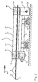
- the device 1 shown in FIGS. 1 and 2 according to the preferred exemplary embodiment for the lateral alignment of printed product 3 located on a conveyor 2 has a frame 4 to which two motor-driven alignment units 5 and 6 are fastened at an adjustable distance from one another .
- the frame 4 of the device 1 has two rods 7 and 8, which are guided under the conveyor 2 transversely to the conveying direction thereof, for the stable connection of the two alignment units.
- the device can thus be set to any width of the delivered printed product or to different widths of the scale flow.
- the two screw terminals 9 and 10 are in turn connected to one another via a support 11 of a support structure of the alignment unit 5 and 6, respectively.
- a gear 12 for example a bevel gear
- a plummer block 14 for a second shaft 15 which is vertically loosely rotatably mounted therein has been arranged, which is non-rotatably connected to a pulley 19 or 19 'which is also designed in the manner of an eccentric and is provided with an eccentric bore.
- Both pulleys 18 and 19 or 18 'and 19' which are designed as eccentrics, are connected to one another via the endless toothed belt 21.21 'in such a way that they are always at the same distance from the conveyor 2 or belt conveyor, which is preferably designed as a belt conveyor, in each position with a full rotation of a scale stream 24 formed from the printed product 3 (approximate phase coherence).
- the two alignment units 5 and 6 are designed in the same manner as described above.
- the two gears 12 of the two units 5 and 6 are mechanically connected to one another via a drive (not shown) on a connecting shaft 23.
- the eccentric pulleys 18,18 'and 19,19' provided relative to one another in pairs, that they operate in opposite directions and the two Zahnriementrum 25,25 'execute a stroke, and the aufrzu- vonrwe g results.
- the two alignment units 5 and 6 can also be operated as a whole by only one motor arranged on one of the two units, but also by means of a gear shaft driving both units, which in turn is driven decentrally by a motor.
- the decentralized drive can be tapped from the conveyor to synchronize the alignment units.
- the desired distance between the two alignment units 5 and 6 - as already mentioned at the beginning - can be set with the help of the screw terminals 9 and 10 as required.
- the frame 4 of the alignment device 1 and the two alignment units 5 and 6 of the same are designed such that one strand 25, 25 'of the two toothed belts 21, 21' on the side facing the conveyor 2 over its entire length parallel to the conveyor 2, i.e. is arranged to run in the direction of conveyance of the shingled stream 24 and that they form a U-shaped channel with the conveyor 2 - seen in cross section - in which the continuous shingled stream 24 is aligned on both sides.
- the two toothed belts 21, 21 ' have a width such that their upper edge 27 projects beyond the printed product 3 located on the conveyor 2.
- the toothed belts can be provided on their outside with a special plastic coating, for example with a Teflon coating. Such a coating can also reduce the coefficient of friction of the belt surface.
- the described holding device for the aligning units 5 and 6 with the frame 4 and the adjusting elements 7, 8 or 9.10 for adjusting the aligning units to different widths of the printed product can also be arranged overhead with respect to the conveyor 2, which still increases the mobility of the entire device favored. In this way too, the two alignment units form a U-shaped channel together with the conveyor.
- the toothed belt 21 arranged on the two alignment units 5 and 6 is subjected to a movement in the direction of arrow 16 by means of the gear 12 and with the aid of a drive motor via the pulley 18 on the side of the strand 25 given a speed which corresponds to the direction of movement and the conveying speed of the conveyor 2.
- the two toothed belts 21,21 ' are displaced into the position shown by a dash-dotted line 17 in FIG. 1 with a full rotation of the pulleys and thereby push the printed product 3 of the scale stream 24 like arranging left and right hands laterally during the conveying process.
- the pulleys 18 and 19 With a further rotation of the pulleys 18 and 19, the movement described above is repeated run of the two toothed belts 21.
- the toothed belts of the alignment units describe a stroke running vertically to the scale flow.
- the runs 25, 25 'running along the shingled stream 24 approach each other to the shingled stream width and push individual disordered shingled stream elements together with a minimal conveying speed in the conveying direction to form an equally wide strand of printed products.
- the disordered stream of shingles pushes into the now wider U-shaped channel and is pushed together again in the next stroke before it has passed through the alignment device.
- the timing belts run approximately at the shingled stream speed when pushed together, so that no unpredictable disorder can occur during the pushing together or in the event of any contact of the shingling stream elements with the toothed belt, e.g. by pushing the shingling stream elements together in the conveying direction (change in the shingled spacing). This happens alternately at a speed that is adapted to the printed product conveyance.
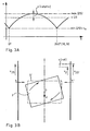
- FIGS. 3A and 3B still show procedural details for the operation of the device according to the invention. These process details also provide information on the dimensioning of functional parts when designing the device and also on the estimation of approximate operating variables such as speeds, timing, etc.
- FIG. 3A shows the speed change of the rotating toothed belt in a speed-time diagram, for example as a moving point viewed on the toothed belt drum 25 or 25 'running parallel to the printed product 3 over a full revolution of the eccentric pulley 18 or 19.
- the position Ograd corresponds to the position of the pulleys, as shown in Figure 1.
- Vmin (25) and Vmax (25) denote on the one hand the minimum speed of a point on the strand 25, that is the basic speed v ⁇ , and on the other hand its maximum speed when touching the printed material during the order stroke.
- the ratio Vmin / Vmax depends on the eccentricity. Example: with a pulley diameter of 6cm to 7cm and an eccentricity of approx.
- An oblique printed product 3 (within the scale flow) is to be aligned by a counter-stroke movement of the toothed belt strand 25, 25 '.
- the printed product which is also inclined to the required scale spacing S, should finally have its original scale spacing in the correct position.
- the alignment device not only corrects skewed printed products into ordered positions, but also lateral displacements, as can occur when they are output from rotary printing. Such shingled streams that are shifted in this way are centered on the conveyor in the lateral direction.
- the differential speed is kept within limits ⁇ v3 to Vmin (25)) and thus practically any increase in the product conveying speed is made possible.
- the eccentricity achieves the order stroke, which is also superimposed on the toothed belt speed as an increase in speed.
- the stroke and ripple of the overall speed can be determined using the eccentricity ratio.
Landscapes
- Engineering & Computer Science (AREA)
- Mechanical Engineering (AREA)
- Separation, Sorting, Adjustment, Or Bending Of Sheets To Be Conveyed (AREA)
- Registering Or Overturning Sheets (AREA)
- Attitude Control For Articles On Conveyors (AREA)
- Non-Silver Salt Photosensitive Materials And Non-Silver Salt Photography (AREA)
- Macromolecular Compounds Obtained By Forming Nitrogen-Containing Linkages In General (AREA)
- Addition Polymer Or Copolymer, Post-Treatments, Or Chemical Modifications (AREA)
- Structure Of Belt Conveyors (AREA)
- Liquid Crystal Substances (AREA)
Priority Applications (1)
| Application Number | Priority Date | Filing Date | Title |
|---|---|---|---|
| AT86112296T ATE48116T1 (de) | 1985-11-26 | 1986-09-05 | Vorrichtung zum seitlichen ausrichten eines schuppenstromes. |
Applications Claiming Priority (2)
| Application Number | Priority Date | Filing Date | Title |
|---|---|---|---|
| CH5041/85A CH668242A5 (de) | 1985-11-26 | 1985-11-26 | Seitenrichter. |
| CH5041/85 | 1985-11-26 |
Publications (2)
| Publication Number | Publication Date |
|---|---|
| EP0223941A1 true EP0223941A1 (fr) | 1987-06-03 |
| EP0223941B1 EP0223941B1 (fr) | 1989-11-23 |
Family
ID=4286951
Family Applications (1)
| Application Number | Title | Priority Date | Filing Date |
|---|---|---|---|
| EP86112296A Expired EP0223941B1 (fr) | 1985-11-26 | 1986-09-05 | Dispositif pour aligner latéralement un courant d'articles se chevauchant |
Country Status (7)
| Country | Link |
|---|---|
| US (1) | US4767116A (fr) |
| EP (1) | EP0223941B1 (fr) |
| JP (1) | JP2538220B2 (fr) |
| AT (1) | ATE48116T1 (fr) |
| CH (1) | CH668242A5 (fr) |
| DE (1) | DE3667045D1 (fr) |
| FI (1) | FI80866C (fr) |
Cited By (3)
| Publication number | Priority date | Publication date | Assignee | Title |
|---|---|---|---|---|
| US7318587B2 (en) | 2003-12-22 | 2008-01-15 | Ferag Ag | Method of, and apparatus for, stabilizing and positioning sheet-like articles |
| US7677559B2 (en) | 2007-01-12 | 2010-03-16 | Ferag Ag | Apparatus for laterally aligning printed products |
| US7810807B2 (en) | 2003-08-07 | 2010-10-12 | Mueller Martini Holding Ag | Device for centering an overlapping sheet flow |
Families Citing this family (15)
| Publication number | Priority date | Publication date | Assignee | Title |
|---|---|---|---|---|
| CA1301136C (fr) * | 1987-03-11 | 1992-05-19 | Yutaka Takashima | Dispositif pour ouvrir une cassette de film et y changer le film |
| US4856956A (en) * | 1987-06-18 | 1989-08-15 | Supac Systems, Inc. | Container extraction and transfer mechanism for an automated storage and retrieval system |
| DE4024037A1 (de) * | 1990-07-28 | 1992-01-30 | Handtmann A Punkt Automation | Einrichtung zum transport von stueckguetern |
| DE59208321D1 (de) * | 1991-11-13 | 1997-05-15 | Ciba Geigy Ag | Beschichtungsvorrichtung für Platten |
| US5226643A (en) * | 1991-12-16 | 1993-07-13 | Eastman Kodak Company | Sheet transport and alignment apparatus with a self-aligning edge-guide |
| DE4235413A1 (de) * | 1992-10-21 | 1994-04-28 | Bielomatik Leuze & Co | Positioniervorrichtung für Stückgut |
| US6257393B1 (en) | 1999-10-29 | 2001-07-10 | Planet Products Corporation | Product collator |
| US6231299B1 (en) | 1999-11-05 | 2001-05-15 | John Robert Newsome | Apparatus for aligning stacked documents moving along a conveyor |
| US6454257B1 (en) | 2000-08-15 | 2002-09-24 | Versa Tech, L.L.C. | Article jogging apparatus |
| US6663104B2 (en) * | 2001-10-18 | 2003-12-16 | Pitney Bowes Inc. | Method and system for aligning moving sheets |
| EP1389592A1 (fr) * | 2002-08-13 | 2004-02-18 | Innopack S.r.l. | Dispositif de transport de piles de feuilles de papier ou similaire |
| NL1027231C2 (nl) * | 2004-10-13 | 2006-04-18 | Townsend Engineering B V | Inrichting en werkwijze voor het positioneren van voortbewegende voedselproducten. |
| DE102006052302A1 (de) * | 2006-11-03 | 2008-05-08 | Atlantic Zeiser Gmbh | Vorrichtung zum Bedrucken flächiger Teile, insbesondere von Plastik-Karten |
| JP5184926B2 (ja) * | 2008-03-14 | 2013-04-17 | 日本金銭機械株式会社 | 紙葉類整合搬送装置 |
| US8079583B2 (en) * | 2008-12-19 | 2011-12-20 | Xerox Corporation | Compiling belt system with moving stapler |
Citations (3)
| Publication number | Priority date | Publication date | Assignee | Title |
|---|---|---|---|---|
| US4015843A (en) * | 1975-10-14 | 1977-04-05 | Tennant James R | Newspaper streamliner |
| DE3113399A1 (de) * | 1981-04-03 | 1982-10-14 | Baldwin-Gegenheimer GmbH, 8900 Augsburg | Ausrichtvorrichtung fuer die kanten eines aus falzprodukten bestehenden schuppenstroms |
| DE3221601A1 (de) * | 1981-06-27 | 1983-03-10 | E.C.H. Will (Gmbh & Co), 2000 Hamburg | Vorrichtung zum ausrichten von kontinuierlich bewegten blattstapeln |
Family Cites Families (6)
| Publication number | Priority date | Publication date | Assignee | Title |
|---|---|---|---|---|
| GB1551723A (en) * | 1975-08-16 | 1979-08-30 | Molins Ltd | Conveyors for rod/like articles |
| US4311474A (en) * | 1979-09-14 | 1982-01-19 | Dayco Corporation | Synchronous belt and method for making the same |
| US4381108A (en) * | 1981-06-29 | 1983-04-26 | Newsome John R | Device for aligning signatures fed in shingled relation |
| JPS5834842U (ja) * | 1981-09-02 | 1983-03-07 | オムロン株式会社 | 紙葉類整列装置 |
| US4502586A (en) * | 1982-03-31 | 1985-03-05 | Artos Engineering Company | Belt type conveyor for conveying wire segments |
| JPS6093038A (ja) * | 1983-10-25 | 1985-05-24 | Nippon Steel Corp | 板状材のパイリング装置 |
-
1985
- 1985-11-26 CH CH5041/85A patent/CH668242A5/de not_active IP Right Cessation
-
1986
- 1986-09-05 AT AT86112296T patent/ATE48116T1/de not_active IP Right Cessation
- 1986-09-05 DE DE8686112296T patent/DE3667045D1/de not_active Expired
- 1986-09-05 EP EP86112296A patent/EP0223941B1/fr not_active Expired
- 1986-09-10 US US06/905,470 patent/US4767116A/en not_active Expired - Lifetime
- 1986-11-21 JP JP61279543A patent/JP2538220B2/ja not_active Expired - Lifetime
- 1986-11-25 FI FI864792A patent/FI80866C/fi not_active IP Right Cessation
Patent Citations (3)
| Publication number | Priority date | Publication date | Assignee | Title |
|---|---|---|---|---|
| US4015843A (en) * | 1975-10-14 | 1977-04-05 | Tennant James R | Newspaper streamliner |
| DE3113399A1 (de) * | 1981-04-03 | 1982-10-14 | Baldwin-Gegenheimer GmbH, 8900 Augsburg | Ausrichtvorrichtung fuer die kanten eines aus falzprodukten bestehenden schuppenstroms |
| DE3221601A1 (de) * | 1981-06-27 | 1983-03-10 | E.C.H. Will (Gmbh & Co), 2000 Hamburg | Vorrichtung zum ausrichten von kontinuierlich bewegten blattstapeln |
Cited By (3)
| Publication number | Priority date | Publication date | Assignee | Title |
|---|---|---|---|---|
| US7810807B2 (en) | 2003-08-07 | 2010-10-12 | Mueller Martini Holding Ag | Device for centering an overlapping sheet flow |
| US7318587B2 (en) | 2003-12-22 | 2008-01-15 | Ferag Ag | Method of, and apparatus for, stabilizing and positioning sheet-like articles |
| US7677559B2 (en) | 2007-01-12 | 2010-03-16 | Ferag Ag | Apparatus for laterally aligning printed products |
Also Published As
| Publication number | Publication date |
|---|---|
| US4767116A (en) | 1988-08-30 |
| FI80866B (fi) | 1990-04-30 |
| ATE48116T1 (de) | 1989-12-15 |
| JPS62130946A (ja) | 1987-06-13 |
| CH668242A5 (de) | 1988-12-15 |
| FI864792A0 (fi) | 1986-11-25 |
| EP0223941B1 (fr) | 1989-11-23 |
| JP2538220B2 (ja) | 1996-09-25 |
| FI80866C (fi) | 1990-08-10 |
| DE3667045D1 (en) | 1989-12-28 |
| FI864792L (fi) | 1987-05-27 |
Similar Documents
| Publication | Publication Date | Title |
|---|---|---|
| EP0223941A1 (fr) | Dispositif pour aligner latéralement un courant d'articles se chevauchant | |
| EP0564901B1 (fr) | Dispositif d'avance pour tÔle | |
| DE2426073B2 (de) | Kurvenrollenvorrichtung für einen Sammelförderer | |
| EP0429884A1 (fr) | Plieuse pour machine d'impression | |
| EP1041027B1 (fr) | Dispositif pour transporter des signatures dans une machine d'imprimerie | |
| DE10334099B3 (de) | Beilagenzusammentragbahn | |
| CH677778A5 (fr) | ||
| EP1640084B1 (fr) | Dispositif d'avance | |
| CH669372A5 (fr) | ||
| EP0267505B1 (fr) | Machine pour déplacer des pièces et similaires | |
| DE2214656C2 (de) | Vorrichtung zum Überführen eines Eingangsstromes aus aneinander anliegenden Gegenständen in einen Ausgangsstrom unter Abstand aufeinanderfolgender Gegenstände | |
| EP0901977B1 (fr) | Dispositif pour faire tourner des articles arrivant en formation imbriquée | |
| DE19649326A1 (de) | Vorrichtung zum Aufteilen eines Stromes von Signaturen | |
| EP4133942B1 (fr) | Paire d'éléments déplaceurs | |
| DD207369A1 (de) | Bogenbeschleunigungsvorrichtung | |
| CH696538A5 (de) | Signaturenübergabevorrichtung. | |
| EP1232964A2 (fr) | Convoyeur courbe | |
| DE29519805U1 (de) | Transfereinrichtung für Fördergut | |
| DE102011117416B4 (de) | Fördereinrichtung mit einem angetriebenen Endloszugmittel für Produkte der Tabak verarbeitenden Industrie | |
| EP0369170B1 (fr) | Machine de nettoyage de récipients, en particulier de bouteilles | |
| DD238320A5 (de) | Vorrichtung zum strecken eines plastischen rohmaterials | |
| WO1997020722A1 (fr) | Dispositif convoyeur | |
| EP0177043B1 (fr) | Dispositif pour marquer des lots de feuilles dénombrés | |
| DE3303332A1 (de) | Foerdereinrichtung zum taktweisen vorschieben von papierlagen | |
| EP1468949B1 (fr) | Dispositif de rupture pour des matériaux en bande |
Legal Events
| Date | Code | Title | Description |
|---|---|---|---|
| PUAI | Public reference made under article 153(3) epc to a published international application that has entered the european phase |
Free format text: ORIGINAL CODE: 0009012 |
|
| AK | Designated contracting states |
Kind code of ref document: A1 Designated state(s): AT DE FR GB IT NL SE |
|
| 17P | Request for examination filed |
Effective date: 19870814 |
|
| 17Q | First examination report despatched |
Effective date: 19880715 |
|
| ITF | It: translation for a ep patent filed | ||
| GRAA | (expected) grant |
Free format text: ORIGINAL CODE: 0009210 |
|
| AK | Designated contracting states |
Kind code of ref document: B1 Designated state(s): AT DE FR GB IT NL SE |
|
| REF | Corresponds to: |
Ref document number: 48116 Country of ref document: AT Date of ref document: 19891215 Kind code of ref document: T |
|
| ET | Fr: translation filed | ||
| REF | Corresponds to: |
Ref document number: 3667045 Country of ref document: DE Date of ref document: 19891228 |
|
| GBT | Gb: translation of ep patent filed (gb section 77(6)(a)/1977) | ||
| PLBE | No opposition filed within time limit |
Free format text: ORIGINAL CODE: 0009261 |
|
| STAA | Information on the status of an ep patent application or granted ep patent |
Free format text: STATUS: NO OPPOSITION FILED WITHIN TIME LIMIT |
|
| 26N | No opposition filed | ||
| ITTA | It: last paid annual fee | ||
| PGFP | Annual fee paid to national office [announced via postgrant information from national office to epo] |
Ref country code: NL Payment date: 19940930 Year of fee payment: 9 |
|
| EAL | Se: european patent in force in sweden |
Ref document number: 86112296.8 |
|
| PGFP | Annual fee paid to national office [announced via postgrant information from national office to epo] |
Ref country code: AT Payment date: 19950906 Year of fee payment: 10 |
|
| PGFP | Annual fee paid to national office [announced via postgrant information from national office to epo] |
Ref country code: FR Payment date: 19950929 Year of fee payment: 10 |
|
| PG25 | Lapsed in a contracting state [announced via postgrant information from national office to epo] |
Ref country code: NL Effective date: 19960401 |
|
| NLV4 | Nl: lapsed or anulled due to non-payment of the annual fee |
Effective date: 19960401 |
|
| PG25 | Lapsed in a contracting state [announced via postgrant information from national office to epo] |
Ref country code: AT Effective date: 19960905 |
|
| PG25 | Lapsed in a contracting state [announced via postgrant information from national office to epo] |
Ref country code: FR Effective date: 19960930 |
|
| REG | Reference to a national code |
Ref country code: FR Ref legal event code: ST |
|
| REG | Reference to a national code |
Ref country code: FR Ref legal event code: ST |
|
| PGFP | Annual fee paid to national office [announced via postgrant information from national office to epo] |
Ref country code: GB Payment date: 19990901 Year of fee payment: 14 |
|
| PG25 | Lapsed in a contracting state [announced via postgrant information from national office to epo] |
Ref country code: GB Free format text: LAPSE BECAUSE OF NON-PAYMENT OF DUE FEES Effective date: 20000905 |
|
| GBPC | Gb: european patent ceased through non-payment of renewal fee |
Effective date: 20000905 |
|
| PGFP | Annual fee paid to national office [announced via postgrant information from national office to epo] |
Ref country code: SE Payment date: 20020829 Year of fee payment: 17 |
|
| PGFP | Annual fee paid to national office [announced via postgrant information from national office to epo] |
Ref country code: DE Payment date: 20020907 Year of fee payment: 17 |
|
| PG25 | Lapsed in a contracting state [announced via postgrant information from national office to epo] |
Ref country code: SE Free format text: LAPSE BECAUSE OF NON-PAYMENT OF DUE FEES Effective date: 20030906 |
|
| PG25 | Lapsed in a contracting state [announced via postgrant information from national office to epo] |
Ref country code: DE Free format text: LAPSE BECAUSE OF NON-PAYMENT OF DUE FEES Effective date: 20040401 |
|
| EUG | Se: european patent has lapsed | ||
| PG25 | Lapsed in a contracting state [announced via postgrant information from national office to epo] |
Ref country code: IT Free format text: LAPSE BECAUSE OF NON-PAYMENT OF DUE FEES;WARNING: LAPSES OF ITALIAN PATENTS WITH EFFECTIVE DATE BEFORE 2007 MAY HAVE OCCURRED AT ANY TIME BEFORE 2007. THE CORRECT EFFECTIVE DATE MAY BE DIFFERENT FROM THE ONE RECORDED. Effective date: 20050905 |