EP0224342A2 - Magnetkopf für das Aufzeichnen und die Wiedergabe - Google Patents
Magnetkopf für das Aufzeichnen und die Wiedergabe Download PDFInfo
- Publication number
- EP0224342A2 EP0224342A2 EP86308488A EP86308488A EP0224342A2 EP 0224342 A2 EP0224342 A2 EP 0224342A2 EP 86308488 A EP86308488 A EP 86308488A EP 86308488 A EP86308488 A EP 86308488A EP 0224342 A2 EP0224342 A2 EP 0224342A2
- Authority
- EP
- European Patent Office
- Prior art keywords
- magnetic head
- core
- head
- slit
- magnetic
- Prior art date
- Legal status (The legal status is an assumption and is not a legal conclusion. Google has not performed a legal analysis and makes no representation as to the accuracy of the status listed.)
- Granted
Links
Images

Classifications
-
- G—PHYSICS
- G11—INFORMATION STORAGE
- G11B—INFORMATION STORAGE BASED ON RELATIVE MOVEMENT BETWEEN RECORD CARRIER AND TRANSDUCER
- G11B5/00—Recording by magnetisation or demagnetisation of a record carrier; Reproducing by magnetic means; Record carriers therefor
- G11B5/127—Structure or manufacture of heads, e.g. inductive
- G11B5/187—Structure or manufacture of the surface of the head in physical contact with, or immediately adjacent to the recording medium; Pole pieces; Gap features
- G11B5/21—Structure or manufacture of the surface of the head in physical contact with, or immediately adjacent to the recording medium; Pole pieces; Gap features the pole pieces being of ferrous sheet metal or other magnetic layers
-
- G—PHYSICS
- G11—INFORMATION STORAGE
- G11B—INFORMATION STORAGE BASED ON RELATIVE MOVEMENT BETWEEN RECORD CARRIER AND TRANSDUCER
- G11B5/00—Recording by magnetisation or demagnetisation of a record carrier; Reproducing by magnetic means; Record carriers therefor
- G11B5/127—Structure or manufacture of heads, e.g. inductive
- G11B5/147—Structure or manufacture of heads, e.g. inductive with cores being composed of metal sheets, i.e. laminated cores with cores composed of isolated magnetic layers, e.g. sheets
Definitions
- This invention relates to a magnetic head for recording and reproducing information on magnetic media.
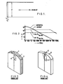
- a magnetic head using an alloy core which is low in specific resistance is susceptible to an eddy current loss to lower the high frequency characteristic of the magnetic head.
- a conventional magnetic head of an alloy core has been made of a core plate whose thickness, namely h in the equation (1), is made as thin as possible.
- an alloy magnetic head as shown in Fig. 3 has been developed.
- the conventional alloy magnetic head comprises a main core 1, two sub cores 2 sandwiching the main core 1 therebetween and two reinforcing glass plates 3 disposed on a magnetic tape abutting the face of the sub cores, in which main core 1 is made of alloy, while the sub cores 2 are made of ferrite.
- the main core 1 and the sub cores 2 are respectively provided with a winding groove 4.
- the alloy magnetic head thus constructed as shown in Fig.
- FIG. 4 there is another conventional magnetic head of a ferrite core as shown in Fig. 4 which is improved in productivity.
- This conventional ferrite magnetic head comprises a main core 5 made of ferrite with a winding groove 4 and two reinforcing glass members 3.
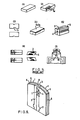
- Fig. 5 shows the producing steps of the ferrite magnetic head mentioned above.
- a core block is cut out from a ferrite material.
- a plurality of head gap grooves each of which is equal to the track width Tw are formed in the core block and thereafter each reinforcing glass member 3 is deposited in the individual head gap groove.
- the winding groove 4 is formed in the core block and a head gap face of the core block is polished.
- a gap material of SiO2 is sputtered on the head gap face.
- the two core blocks are secured together by glass depositing so that the two gap faces are confronting to each other.
- a composite body made up of the two core blocks is cut to provide plurality of head chips at the azimuth angle. Shadowed portions in the figure depict cutting off areas.
- the head chip is mounted on an electrode circuit board and its face to be confronting to magnetic recording media is polished and a coil is wound around the head chip. The ferrite magnetic head thus conducted as shown in Figs. 4 and 5 is still not free from the problem that its saturation flux density is low.
- the magnetic head of this invention has a core made of alloy material and reinforced with a nonmagnetic material member which is composed of two identical component bodies secured by glass-depositing and forming a head gap therebetween.
- Each of the component bodies has a head gap edge whose width is equal to the track width of a magnetic head and a body whose width is broader than the track width.
- the component has at least one slit formed therein.
- Fig. 6 is a perspective view of the magnetic head according to one embodiment of the invention.
- the magnetic head comprises a composite core which has two core component bodies 1 and is reinforced with nonmagnetic material such as glass members 3 and 6.
- the core component bodies are made of alloy and has a slit 9 formed on each side thereof.
- the two core component bodies 1 are secured by glass depositing at their confronting surfaces shown in Fig. 6 and a head gap 8 is formed between them.
- a thickness of the head gap edge is equal to the track width of a magnetic tape.
- the reinforcing glass mem ber 3 is disposed on both surfaces covering the joint of the two core component bodies 1.
- the reinforcing glass memmber 6 is disposed within the slit 9 of the individual core component body 1.
- a winding opening 4 is formed in one of the core component bodies 1 and the reinforcing glass members 3 and 6.
- a glass opening 7 is formed in each core component 1 and the reinforcing glass member 3 is deposited to join the reinforcing glass member 6 at the glass opening 7.
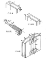
- Fig. 7 shows steps for producing the magnetic head shown in Fig. 6.
- an alloy material is cut to form a core block.
- a plurality of the head gap edges whose each width is equal to the track width Tw and the glass opening 7 is formed in the core block, and thereafter the reinforcing glass member 3 is disposed between the head gap edges and within the glass opening 7.
- a plurality of the slits 9 are formed in the core block and thereafter the reinforcing glass member 6 is disposed within the slits 6.
- Fig. 8 is a enlarged view of the core block having the slits 9.
- the winding opening 4 is formed in the core block and a head gap surface of the core block is polished.
- a gap material of SiO2 is sputtered on the head gap surface.
- the two core blocks are secured together by glass depositing at the head gap confronting surfaces.
- a block material of the two core blocks is cut to form a plurality of head chips, namely the core shown in Fig. 6, at the azimuth angle. The shadowed portions depict the cutting off areas.
- the head chip is fixed to an electrode circuit board and its magnetic tape abutting face is polished and a coil is wound around the head chip.
- the slit in the core As described above, it is possible to utilize the conventional process for producing the ferrite core as shown in Figs. 4 and 5, and at the same time, the thinning of a core thickness is realized. Therefore, the sub core as shown in Fig. 3 is not required. In the equation (1), the eddy current loss is also reduced because of the thickness h of the core becoming thinner, which overcomes the effect of the alloy core being low in the specific resistance ⁇ .
- an azimuth recording is adopted. Namely, a plane of the core and a direction of the track width of the head gap thereof make an azimuth angle.
- the slit is formed parallel to the cutting off portion as shown in Fig. 8, the slit and the direction of the track width of the head gap make the azimuth angle, which results to minimize the thickness of the core.
- a slit with a V-shaped bottom as shown in Fig. 9 is more advantageous than that of a flat-shaped bottom as shown in Fig. 10.
- the slit can be formed at a right angle with respect to the direction of the track width of the head gap as shown in Fig. 11 and it is possible to decrease the producing price of the magnetic head.
- Fig. 11 illustrates the core having a plurality of slits.
- the nonmagnetic material such as the reinforcing glass is disposed within the slit and around the head gap edge. Nevertheless, the bonding intensity between the core material and the nonmagnetic material is not usually sufficient because the thermal-expansion coefficient between them is different and the chemical affinity is lacking.
- the glass opening 7 is formed in the core as shown in Fig. 12 and a reinforcing glass member is disposed within the glass opening 7, namely the reinforcing glass 3 is deposited to the reinforcing glass member 6 at the glass opening 7.
- the reinforcing glass members 3 and 6 are divided into four portions with the two core component bodies 1, the four reinforcing glass members 3 and 6 are linked to one reinforcing glass member within the core by disposing the reinforcing glass member within the glass opening 7. Accordingly, it is possible to increase the mechanical strength of the core without depending on the chemical bonding intensity between the core material and the nonmagnetic material.
Landscapes
- Engineering & Computer Science (AREA)
- Manufacturing & Machinery (AREA)
- Magnetic Heads (AREA)
Applications Claiming Priority (2)
| Application Number | Priority Date | Filing Date | Title |
|---|---|---|---|
| JP255435/85 | 1985-11-14 | ||
| JP60255435A JPS62114108A (ja) | 1985-11-14 | 1985-11-14 | 電磁変換素子 |
Publications (3)
| Publication Number | Publication Date |
|---|---|
| EP0224342A2 true EP0224342A2 (de) | 1987-06-03 |
| EP0224342A3 EP0224342A3 (en) | 1988-11-17 |
| EP0224342B1 EP0224342B1 (de) | 1992-05-20 |
Family
ID=17278724
Family Applications (1)
| Application Number | Title | Priority Date | Filing Date |
|---|---|---|---|
| EP86308488A Expired EP0224342B1 (de) | 1985-11-14 | 1986-10-30 | Magnetkopf für das Aufzeichnen und die Wiedergabe |
Country Status (4)
| Country | Link |
|---|---|
| US (1) | US4821134A (de) |
| EP (1) | EP0224342B1 (de) |
| JP (1) | JPS62114108A (de) |
| DE (1) | DE3685408D1 (de) |
Cited By (2)
| Publication number | Priority date | Publication date | Assignee | Title |
|---|---|---|---|---|
| EP0578234A3 (de) * | 1992-07-08 | 1994-02-16 | Sharp Kk | |
| EP0725387A3 (de) * | 1991-04-19 | 1996-08-14 | Sony Corporation | Magnetkopfherstellungsverfahren |
Families Citing this family (6)
| Publication number | Priority date | Publication date | Assignee | Title |
|---|---|---|---|---|
| JP2759271B2 (ja) * | 1989-01-17 | 1998-05-28 | 日本ビクター株式会社 | 磁気ヘッドとその製造方法 |
| US5208965A (en) * | 1989-01-17 | 1993-05-11 | Victor Company Of Japan, Ltd. | Method for producing magnetic head having track regulation grooves formed at tape sliding surface |
| US5684661A (en) * | 1995-04-13 | 1997-11-04 | Eastman Kodak Company | Magnetic head assembly and method for reading and/or writing data onto a thin magnetic layer placed on a photographic element |
| AU2001286255A1 (en) * | 2000-09-14 | 2002-03-26 | Matsushita Electric Works Ltd. | Electromagnetic device and high-voltage generating device and method of producing electromagnetic device |
| JP2002312907A (ja) * | 2001-04-13 | 2002-10-25 | Sony Corp | 磁気ヘッドおよびその製造方法 |
| JP4851062B2 (ja) * | 2003-12-10 | 2012-01-11 | スミダコーポレーション株式会社 | インダクタンス素子の製造方法 |
Family Cites Families (8)
| Publication number | Priority date | Publication date | Assignee | Title |
|---|---|---|---|---|
| JPS5237414A (en) * | 1975-09-20 | 1977-03-23 | Canon Inc | Magnetic head |
| JPS5370808A (en) * | 1976-12-07 | 1978-06-23 | Victor Co Of Japan Ltd | Magnetic head |
| JPS55122224A (en) * | 1979-03-15 | 1980-09-19 | Sanyo Electric Co Ltd | Production of magnetic head |
| JPS59142716A (ja) * | 1983-02-04 | 1984-08-16 | Hitachi Ltd | 磁気ヘツドおよびその製造方法 |
| JPS6074106A (ja) * | 1983-09-30 | 1985-04-26 | Victor Co Of Japan Ltd | 磁気ヘツド |
| JPS60231903A (ja) * | 1984-05-02 | 1985-11-18 | Hitachi Ltd | 複合型磁気ヘツドおよびその製造方法 |
| JPH0758527B2 (ja) * | 1986-01-10 | 1995-06-21 | 株式会社日立製作所 | 磁気ヘツド |
| JPH05237414A (ja) * | 1992-02-28 | 1993-09-17 | Sawafuji Electric Co Ltd | 静電式圧縮空気浄化器 |
-
1985
- 1985-11-14 JP JP60255435A patent/JPS62114108A/ja active Pending
-
1986
- 1986-10-30 DE DE8686308488T patent/DE3685408D1/de not_active Expired - Lifetime
- 1986-10-30 EP EP86308488A patent/EP0224342B1/de not_active Expired
- 1986-11-12 US US06/929,313 patent/US4821134A/en not_active Expired - Lifetime
Cited By (4)
| Publication number | Priority date | Publication date | Assignee | Title |
|---|---|---|---|---|
| EP0725387A3 (de) * | 1991-04-19 | 1996-08-14 | Sony Corporation | Magnetkopfherstellungsverfahren |
| US6014291A (en) * | 1991-04-19 | 2000-01-11 | Sony Corporation | Composite magnetic head having thin conductor film |
| EP0578234A3 (de) * | 1992-07-08 | 1994-02-16 | Sharp Kk | |
| US5691866A (en) * | 1992-07-08 | 1997-11-25 | Sharp Kabushiki Kaisha | Magnetic head and method of manufacturing the same |
Also Published As
| Publication number | Publication date |
|---|---|
| JPS62114108A (ja) | 1987-05-25 |
| EP0224342A3 (en) | 1988-11-17 |
| EP0224342B1 (de) | 1992-05-20 |
| DE3685408D1 (de) | 1992-06-25 |
| US4821134A (en) | 1989-04-11 |
Similar Documents
| Publication | Publication Date | Title |
|---|---|---|
| EP0650628B1 (de) | Zusammengesetzter metall- und ferritwandlerkopf und herstellungsverfahren dafür | |
| US4775909A (en) | Magnetic head using a magnetic thin film and first, second and third core members | |
| US5157569A (en) | Thin film magnetic head | |
| US4788611A (en) | Magnetic transducer head | |
| EP0224342A2 (de) | Magnetkopf für das Aufzeichnen und die Wiedergabe | |
| US4602307A (en) | Compound type magnetic head | |
| US4811146A (en) | Composite magnetic head | |
| US5267392A (en) | Method of manufacturing a laminated high frequency magnetic transducer | |
| US4369477A (en) | Magnetic head and method of manufacturing the same | |
| KR930000067B1 (ko) | 자기헤드 | |
| EP0108152A1 (de) | Zusammengesetzte, digitale magnetköpfe mit schmaler spurbreite | |
| US4731299A (en) | Composite magnetic material | |
| KR0152601B1 (ko) | 복합형 자기헤드 코아 및 그 제조방법 | |
| JPS62262209A (ja) | 磁気ヘツド | |
| KR910000207B1 (ko) | 복합형 자기헤드 | |
| JPS62222412A (ja) | 磁気ヘツド及びその製造方法 | |
| JPS61107510A (ja) | 磁気ヘツド | |
| JPH0354704A (ja) | 磁気ヘッドとその製造方法 | |
| JPS58222427A (ja) | 磁気ヘツドの製造方法 | |
| JPH1091912A (ja) | 磁気ヘッド | |
| EP0559431A1 (de) | Kleiner Metallkern-Wandlerkopf und Herstellungsverfahren dafür | |
| JPS60185214A (ja) | 磁気ヘツド | |
| JPH0648529B2 (ja) | 磁気ヘツド | |
| JPH05166122A (ja) | 電算機用浮上型磁気ヘッド | |
| JPS63241707A (ja) | 磁気ヘツド |
Legal Events
| Date | Code | Title | Description |
|---|---|---|---|
| PUAI | Public reference made under article 153(3) epc to a published international application that has entered the european phase |
Free format text: ORIGINAL CODE: 0009012 |
|
| AK | Designated contracting states |
Kind code of ref document: A2 Designated state(s): DE FR GB |
|
| PUAL | Search report despatched |
Free format text: ORIGINAL CODE: 0009013 |
|
| RHK1 | Main classification (correction) |
Ipc: G11B 5/147 |
|
| AK | Designated contracting states |
Kind code of ref document: A3 Designated state(s): DE FR GB |
|
| 17P | Request for examination filed |
Effective date: 19890511 |
|
| 17Q | First examination report despatched |
Effective date: 19901026 |
|
| GRAA | (expected) grant |
Free format text: ORIGINAL CODE: 0009210 |
|
| AK | Designated contracting states |
Kind code of ref document: B1 Designated state(s): DE FR GB |
|
| REF | Corresponds to: |
Ref document number: 3685408 Country of ref document: DE Date of ref document: 19920625 |
|
| ET | Fr: translation filed | ||
| REG | Reference to a national code |
Ref country code: GB Ref legal event code: 727 |
|
| REG | Reference to a national code |
Ref country code: GB Ref legal event code: 727A |
|
| REG | Reference to a national code |
Ref country code: GB Ref legal event code: 727B |
|
| PLBE | No opposition filed within time limit |
Free format text: ORIGINAL CODE: 0009261 |
|
| STAA | Information on the status of an ep patent application or granted ep patent |
Free format text: STATUS: NO OPPOSITION FILED WITHIN TIME LIMIT |
|
| 26N | No opposition filed | ||
| REG | Reference to a national code |
Ref country code: GB Ref legal event code: 746 Effective date: 20010103 |
|
| REG | Reference to a national code |
Ref country code: FR Ref legal event code: D6 |
|
| PGFP | Annual fee paid to national office [announced via postgrant information from national office to epo] |
Ref country code: FR Payment date: 20011010 Year of fee payment: 16 |
|
| PGFP | Annual fee paid to national office [announced via postgrant information from national office to epo] |
Ref country code: GB Payment date: 20011031 Year of fee payment: 16 |
|
| PGFP | Annual fee paid to national office [announced via postgrant information from national office to epo] |
Ref country code: DE Payment date: 20011112 Year of fee payment: 16 |
|
| REG | Reference to a national code |
Ref country code: GB Ref legal event code: IF02 |
|
| PG25 | Lapsed in a contracting state [announced via postgrant information from national office to epo] |
Ref country code: GB Free format text: LAPSE BECAUSE OF NON-PAYMENT OF DUE FEES Effective date: 20021030 |
|
| PG25 | Lapsed in a contracting state [announced via postgrant information from national office to epo] |
Ref country code: DE Free format text: LAPSE BECAUSE OF NON-PAYMENT OF DUE FEES Effective date: 20030501 |
|
| GBPC | Gb: european patent ceased through non-payment of renewal fee | ||
| PG25 | Lapsed in a contracting state [announced via postgrant information from national office to epo] |
Ref country code: FR Free format text: LAPSE BECAUSE OF NON-PAYMENT OF DUE FEES Effective date: 20030630 |
|
| REG | Reference to a national code |
Ref country code: FR Ref legal event code: ST |