EP0225038B1 - Relais électromagnétique polarisé - Google Patents
Relais électromagnétique polarisé Download PDFInfo
- Publication number
- EP0225038B1 EP0225038B1 EP86308273A EP86308273A EP0225038B1 EP 0225038 B1 EP0225038 B1 EP 0225038B1 EP 86308273 A EP86308273 A EP 86308273A EP 86308273 A EP86308273 A EP 86308273A EP 0225038 B1 EP0225038 B1 EP 0225038B1
- Authority
- EP
- European Patent Office
- Prior art keywords
- magnetic
- electromagnetic relay
- polarized electromagnetic
- yoke
- protrusions
- Prior art date
- Legal status (The legal status is an assumption and is not a legal conclusion. Google has not performed a legal analysis and makes no representation as to the accuracy of the status listed.)
- Expired
Links
- 239000011347 resin Substances 0.000 claims description 14
- 229920005989 resin Polymers 0.000 claims description 14
- 239000000696 magnetic material Substances 0.000 claims description 8
- 230000003014 reinforcing effect Effects 0.000 claims description 8
- 238000000465 moulding Methods 0.000 claims description 6
- 230000004048 modification Effects 0.000 description 16
- 238000012986 modification Methods 0.000 description 16
- XEEYBQQBJWHFJM-UHFFFAOYSA-N Iron Chemical group [Fe] XEEYBQQBJWHFJM-UHFFFAOYSA-N 0.000 description 11
- 238000005452 bending Methods 0.000 description 8
- 238000000034 method Methods 0.000 description 7
- 238000010276 construction Methods 0.000 description 6
- 238000010586 diagram Methods 0.000 description 4
- 230000004907 flux Effects 0.000 description 4
- 229910052742 iron Inorganic materials 0.000 description 4
- 239000002131 composite material Substances 0.000 description 3
- 238000004519 manufacturing process Methods 0.000 description 3
- 244000145845 chattering Species 0.000 description 2
- 230000002950 deficient Effects 0.000 description 2
- 230000000694 effects Effects 0.000 description 2
- 238000007789 sealing Methods 0.000 description 2
- 229910000906 Bronze Inorganic materials 0.000 description 1
- OAICVXFJPJFONN-UHFFFAOYSA-N Phosphorus Chemical compound [P] OAICVXFJPJFONN-UHFFFAOYSA-N 0.000 description 1
- 230000002411 adverse Effects 0.000 description 1
- 239000010974 bronze Substances 0.000 description 1
- KUNSUQLRTQLHQQ-UHFFFAOYSA-N copper tin Chemical compound [Cu].[Sn] KUNSUQLRTQLHQQ-UHFFFAOYSA-N 0.000 description 1
- 238000005520 cutting process Methods 0.000 description 1
- 238000002347 injection Methods 0.000 description 1
- 239000007924 injection Substances 0.000 description 1
- 238000007689 inspection Methods 0.000 description 1
- 230000001050 lubricating effect Effects 0.000 description 1
- 229910001004 magnetic alloy Inorganic materials 0.000 description 1
- 230000007257 malfunction Effects 0.000 description 1
- 239000000463 material Substances 0.000 description 1
- 239000002184 metal Substances 0.000 description 1
- 229910052751 metal Inorganic materials 0.000 description 1
- 239000002245 particle Substances 0.000 description 1
- 238000003825 pressing Methods 0.000 description 1
Images







Classifications
-
- H—ELECTRICITY
- H01—ELECTRIC ELEMENTS
- H01H—ELECTRIC SWITCHES; RELAYS; SELECTORS; EMERGENCY PROTECTIVE DEVICES
- H01H51/00—Electromagnetic relays
- H01H51/22—Polarised relays
- H01H51/2227—Polarised relays in which the movable part comprises at least one permanent magnet, sandwiched between pole-plates, each forming an active air-gap with parts of the stationary magnetic circuit
Definitions
- the present invention relates to a polarized electromagnetic relay (hereunder referred to as "PE relay”) which comprises an electromagnetic block including an iron core and a coil wound thereon, and a pair of permanent magnet units.
- PE relay polarized electromagnetic relay
- a polarized electromagnetic relay which has a core on which a coil is wound, a yoke having a pair of legs at each end and a pair of movable armature blocks each having a permanent magnet and pole pieces, the pole pieces being disposed in working gaps between the pairs of legs and the core and the armature blocks being slidably supported by guides arranged perpendicularly to the axis of the core.
- a magnetic circuit construction of the conventional PE relay includes a generally I-shaped iron core 91 on which an energizing coil 92 is wound, a yoke 93 having at each of the opposite ends thereof a pair of opposing end pieces 93a and 93b and a movable block 97.
- the block 97 is composed of a supporting member of a non-magnetic material having at the opposite ends thereof permanent magnet units 96a and 96b, respectively.
- Each of the units 96a and 96b is composed of a permanent magnet 95 and a pair of magnetic plates 94a and 94b attached to the magnetic poles of the magnet 95, respectively.
- the opposite ends of the core 91 are disposed between the yoke end pieces 93a and 93b, respectively, to form four magnetic gaps between the opposite end surfaces of the core 91 and the end pieces 93a and 93b of the yoke 93.
- the magnet units 96a and 96b are arranged such that each of the magnetic plates 94a and 94b is positioned in one of the four gaps to form energizing spaces, with the end piece 93a, the magnetic plate 94a, the end of the core 91, the magnetic plate 94b and the end piece 93b being layered.
- the movable block 94 responds to a direction of current to be supplied to the coil 92 to move in either direction A or B under a guidance of a coil spool (not shown) or a base member (not shown) to thereby actuate contact members (not shown).
- the core 91 and the end pieces 93a and 93b are arranged oppositely at the same height. Therefore, in order to transmit a magnetic force exerting on the plates 94a and 94b to contact members (not shown) disposed outside the permanent magnet units 96a and 96b, the movable block 97 for supporting the magnet units should have an actuating part formed to avoid the contact with the end pieces 93a and 93b. As a result, it becomes impossible to transmit a composite force exerting on the magnet units 96a and 96b to the contact members efficiently.
- the actuating member satisfying the above requirement should be so thin that it is impossible to obtain a sufficient mechanical strength of the relay. To resolve this problem, the height and thickness of the movable block 97 should be large enough, respectively, which leads an increased size of the relay.
- the magnet units 96a and 96b tend to move in the same direction.
- the units 96a and 96b are connected to each other by the supporting member, it is difficult to obtain a smooth switching operation. This is due to the facts that it is difficult to move a long member such as the movable block 97 in parallel because of friction between the magnet units 96a and 96b and the guide member (not shown) and that one of the magnet units tends to delay in operation with respect to the other. Bending and/or twisting of the movable block 97 which is long with respect to its width may affect the smooth movement of the movable block adversely.
- the productivity of the base member may be lowered due to an additional probability of the occurrence of defective lead terminals and/or movable contact springs which constitute the contact members.
- the length of the base member is large compared with the width thereof, the tendency of bending and twisting thereof is increased, and thus dimensional accuracy of an assembled relay is lowered and relative positions of the contact members (not shown) may vary, causing a malfunction to occur.
- a polarized relay having a yoke body which is bifurcated at one end, and a core wound with a coil, one end of the core being disposed within the bifurated portions of the yoke body and being of a polarity which is different from that of each of the bifurcated portions.
- a movable C-shaped permanent magnet block having its legs in the spaces between the bifuracted portions and the end of the core is moved according to the energisation of the core.
- An object of the present invention is to provide an improved PE relay.
- a bistable type electromagnetic relay comprises: a movable block including a pair of permanent magnet units, each composed of a permanent magnet and a pair of generally U-shaped magnetic plates attached to opposite magnetic poles of said permanent magnet, respectively, each said magnetic plate having a first end and a second end, said first end and second end of each of said magnetic plates being opposed when attached to the poles of said permanent magnet, respectively, and a supporting member for supporting said permanent magnet units at opposite ends thereof, respectively, and for actuating contact members responsive to movements of said permanent magnet units; a core having opposite ends placed between the first ends of said magnetic plates, respectively; a yoke having opposite ends, each formed by a pair of opposing end pieces, the second ends of said magnetic plates being arranged in spaces, each defined by said opposing end pieces, respectively; a spool including a through-hole formed longitudinally through which said core is inserted, flanges formed at opposite ends and a center portion thereof, respectively, a plurality of protrusions protruding out
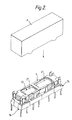
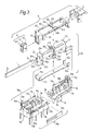
- an embodiment of the invention comprises a movable block 6 including a pair of permanent magnets, an electromagnetic block 20 including an iron core and a yoke, a pair of base members 7a and 7b equipped with contact members (70a and 70b, in Fig. 3) and a cover member 8 for covering the base members 7a and 7b.
- the movable block 6 is composed of a supporting member 60 and permanent magnet units 4 and 5 provided in opposite end portions of the supporting member 60, respectively.
- Each of the magnet units 4 and 5 is composed of the permanent magnet 43(53), a pair of generally U-shaped magnetic plates 41 and 42(51 and 52) attached to opposite magnetic poles of the magnet 43(53), respectively.
- the plates 41 and 51 are attached to N poles of the magnets 43 and 53, respectively, and the plates 42 and 52 are attached to S poles of the magnets 43 and 53, respectively.
- the magnetic plates 41, 42, 51 and 52 are of magnetic material such as iron.
- the supporting member 60 includes supporting portions 65 for supporting the units 4 and 5, contact spring actuating parts 64 provided on both sides of each supporting portion 65, a connecting portion 62 having four bearing protrusions 61a, 61b, 61c and 61d which constitute a bearing portion and an insert-molded reinforcing frame 63.
- the electromagnetic block 20 is composed of the core 1, a coil spool 2, a coil 27 wound on the spool 2 and a yoke 3.
- the core 1 is of magnetic material such as pure iron and inserted into a through hole 24 formed longitudinally in the spool 2.
- the spool 2 has flanges 21a, 21b and 21c provided at both ends and a center thereof, respectively.
- the flanges 21a and 21c are formed with paired legs 25a and 25c, respectively.
- the legs 25a have protrusions 22a and 24a on both side thereof for engagement with the base 7a, and the legs 25c have similar protrusions 22c and 24c on both side thereof for engagement with the base 7b.
- the flange 21b is formed with paired legs 25b.
- the legs 25b have protrusions 22b and 24b on both sides thereof.
- the flange 21b further includes a pair of pins 26a and 26b formed on an upper portion thereof which constitute a rotary shaft for the movable block 6 and each of which has a generally semicircular cross section.
- the yoke 3 is of magnetic material such as iron and has a pair of upright end pieces 31a and 31b at one end thereof and a pair of upright end pieces 32a and 32b at the other end thereof. The yoke 3 is fixedly supported by the paired legs 25a, 25b and 25c of the flanges.
- the base members 7a and 7b have contact members 70a and 70b, respectively.
- the member 70a includes a movable contact spring 72a having one end fixed to a common terminal 71a and the other end positioned between a stationary contact terminal 73a (e.g. a make side terminal) and another stationary contact terminal 74a (e.g. a break side terminal).
- the member 70b includes a movable contact spring 72b having one end fixed to a common terminal 71b and the other end positioned between stationary contact terminals 73b (e.g. make side) and 74b (e.g. break side). A switching operation between the make and break sides is performed by the actuating part 64 of the movable block 6.
- the base member 7b is constituted identically to the base member 7a with an arrangement of the contact members being symmetrical with respect to the base member 7a.
- Movable contacts are formed on both surfaces of free ends of the contact springs 72a and 72b, respectively.
- a stationary contacts is formed on an inner surface of each of the electrically conductive terminals 73a, 73b, 74a and 74b, to face to the electrically conductive springs 72a and 72b.
- Each of the base members 7a and 7b is formed with grooves 75 and recesses 77 and protrusions 76 and 78 for assembling purpose to the spool 2.
- the spool 2 is fixedly secured to the base members 7a and 7b by engaging the protrusions 22a and 24a, and the protrusions 22c and 24c with the grooves 75 and the protrusions 76 of the base members 7a and 7b, respectively.
- the protrusions 22b and 24b are engaged with the recesses 77 and the protrusions 78 of the bases 7a and 7b.
- a pair of coil terminals 79a and 79b are press-fitted to either one of the base members 7a and 7b for an electrical connection to the coil 27.
- the relay is assembled by assembling the movable block 6 to the electromagnetic block 20 with the opposite ends 1a and 1b of the core 1 being sandwiched between the magnetic plates 41, 42 and 51, 52, respectively, and putting the cover 8 thereon.
- the spool 2, the base members 7a and 7b and the cover 8 are of electrically insulative resin material.
- the relay of the present invention is composed, basically, of the block 20 (including the core 1, the coil 27 and the yoke 3) and the movable block 6 including the pair of the magnet units 4 and 5.
- the end pieces 31a and 31b formed in the one end portion of the yoke 3 are formed in a facing relation by bending them at right angle, and the end pieces 32a and 32b formed in the other end portion of the yoke 3 are bended similarly.
- the height of the pieces 31a, 31b, 32a and 32b are determined to be lower than the position of the core 1.
- Each of the magnetic plates 41, 42, 51 and 52 has an upper end 41a, 42a, 51a and 52a and a lower end 41b, 42b, 51b and 52b, respectively.
- the core ends 1a and 1b are positioned between the upper ends 41a and 42a of the plates 41 and 42 and between the upper ends 51a and 52a of the plates 51 and 52, respectively.
- the movable block 6 is positioned such that the lower plate ends 41b and 42b are positioned within a space defined between the yoke end pieces 31a and 31b in facing relations thereto and the lower plate ends 51b and 52b are positioned within a space defined between the yoke end pieces 32a and 32b.
- the plates 41 and 51 and the plates 42 and 52 serve as N poles and S poles, respectively, due to the permanent magnets 43 and 53.
- the core 1 is magnetized by a current supplied to the coil 27 wound thereon, with the core ends 1a and 1b being opposite magnetic polarities which depend upon the direction of the current.
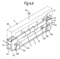
- the movable block 6 is pivotted in an arrow direction (Fig. 4A) due to an attractive or reactive force exerting between the stationary poles by the magnets 43 and 53 and the switchable poles of the core 1 produced by energization of the coil 27.
- a center shaft 69 of the pivot motion of the block 6 is constituted with the pins 26a and 26b of the spool 2 and the protrusions 61a, 61b, 61c and 61d of the movable block 6.
- FIG. 5A the magnet units 4 and 5 are shown in a state in which the plate end 42b of the unit 4 is attracted to the side of the yoke end piece 31a and the plate end portion 51b of the unit 5 is attracted to the side of the yoke end piece 32b.
- Magnetic flux ⁇ A passes from the magnet 43 through the plate end 41a - the core end 1a - the core end 1b - the plate end 52a - the magnet 53 - the plate end 51b - the yoke end piece 32b - the yoke end piece 31a - the plate end 42b - the magnet 43, providing a closed magnetic circuit to hold the attracted condition.
- Magnetic flux ⁇ B forms a closed magnetic circuit in the path, the magnet 43 through the plate end 41b - the yoke end pieces 31b - the yoke end pieces 32a - the plate end 52b - the magnet 53 - the plate end 51a - the core ends 1b - the core end 1a - the plate end 42a - the magnet 43.
- the block 6 holds the state by itself due to the magnetic flux of the magnets 43 and 53. That is, the block 6 operates bidirectistily to form a bistable type relay.
- Fig. 6 shows a magnetic structure wherein a distance A between a right side surface of the core end 1a and an inside surface of the yoke end piece 31b does not coincide with a distance B between an inside surface of the magnetic plate 42 and an outside surface of the plate 41 (A > B) due to insufficient precision in bending work on the yoke end pieces 31a and 31b.
- the magnet unit 4 is subjected to a rotational force Q acting around a fulcrum point P and rotated clockwisely within a range defined by guide members (not shown) while tilting, so that the end piece 31b can be in contact with the plate end 41b.
- the core end 1a, the yoke end pieces 31a and 31b and the plate ends 41a, 41b, 51a and 51b can contact with each other, respectively, even if the bending inaccuracy of the yoke 3 and/or the assembling inaccuracy of the electromagnet block 20 is not negligible.
- a magnetic structure of a monostable type PE relay according to the present invention will be described below.
- a first modification of the magnetic structure shown in Fig. 4 is made so that the size of the yoke end piece 31a (32b) is made different from that of 31b (32a).
- the area of the yoke end piece 31b (32a) facing to the magnet unit 4 (5) is larger than that of the yoke end piece 31a (32b) facing to the magnet unit 4 (5). Therefore, the magnetic resistance on the side of the yoke end piece 31a (32b) is larger than the other, and the magnetic resistance balance is disturbed.
- the magnet units 4 and 5 are attracted to the yoke end pieces 31b and 32a, respectively, due to a composite force of the magnetic forces and the spring forces when deenergized.
- the magnet units 4 and 5 are attracted to the yoke end pieces 31a and 32b, respectively, to actuate the contact members (not shown).
- a second modification of the structure shown in Fig. 4 is made so that the yoke end pieces 31a and 32b are removed to provide an unbalanced magnetic resistances.
- a third modification of the structure in Fig. 4 is made so that the areas of the plate ends 42b and 51b are reduced to obtain an unbalanced magnetic resistances.
- Fig. 8A shows a fourth modification of the structure in Fig. 4.
- a residual plate of non-magnetic material is used to form an air gap in the magnetic circuit thereof.
- Thick residual plates 44a are provided on an inside surface of the plate end 41a and on an outside surface of the plate end 42b, respectively, and thin residual plates 44b are provided on an inside surface of the plate end 42a and on an outside surface of the plate 41b, respectively.
- the plates 44a and 44b function to release the contact condition of the plates 41 and 42 with the yoke end pieces 31a, 31b and the core end 1a smoothly when the magnet unit 4 is moved and to make the magnetic resistances of the circuit unbalanced due to the difference in thickness.
- a fifth modification of the structure in Fig. 4 is made so that the residual plates 44a and 44b are attached to the core end 1a on the side of the end piece 31b and on the side of the yoke end piece 31a, respectively.
- Fig. 8C shows a modification of the magnetic structure having the yoke 3 shown in Fig. 7B.
- the yoke end piece 31a is eliminated and the residual plates 44 are attached to the inside and outside surfaces of the plate 41.
- Fig. 8D shows another modification of the structure having the yoke 3 shown in Fig. 7B.
- a stopper 33 of non-magnetic material such as non-magnetic alloy is mounted by, for example, pressure pressing, instead of the eliminated yoke end piece 31a.
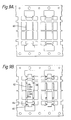
- the supporting member 60 shown in Fig. 3 will be described with reference to Figs. 9A to 9C.
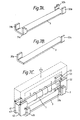
- a plurality of the supporting members 60 can be produced simultaneously described as follows: preparing a plate of non-magnetic, high strength metal such as phosphor bronze and having a plurality of mutually connected reinforcing frames 63 (Fig. 9A); insert-molding the frames 63 with insulating resin; forming the supporting parts 65, the actuating parts 64 and the connecting portions 62 including the bearing protrusions 61a, 61b, 61c and 61d; and cutting portions shown by dotted lines (Fig. 9B) away.
- the frame 63 when resin is injected with too much pressure, the frame 63 may be bent and/or deformed. Therefore, it is desired to minimize the molded portion and to increase the number of connecting points connecting the frames 63 each other in the molding process. However, if the thickness of the resin can be controlled suitably, it may be possible to mold all of the frames 63 and then to form the members 60.
- each actuating part 64 is formed with a slit 640 into which the contact member is to be inserted. In upper portions of the yoke end pieces 31a and 31b, which are lower in level than the core end 1a, spaces are provided.
- the actuating part 64 can transmit linearly a magnetic force acting on the magnetic plates 41 and 42 with the aid of the spaces and provide a sufficient structural strength without increasing the height of the supporting member 60.
- Fig. 9D shows the bearing structure for guiding the rotation of the movable block 6 (Fig. 3), in detail.
- the pins 26a and 26b protruding upwardly from the flange 21b of the spool 2 are disposed in between the bearing protrusions 61a and 61b provided in the connecting portion 62 of the supporting member 60 and in between the bearing protrusions 61c and 61d provided in the same, respectively. That is, the pins 26a and 26b are held loosely with the connecting portion 62 being there-between, so that the movable block 6 can be pivotted in arrow directions.
- the supporting member 60 is compact in size and light weight while having a sufficient mechanical strength and accuracy to realize a satisfactory contact switching operation.
- the base member 7a is pushed up to the structure until the protrusions 22a of the spool 2 reach the bottom of the grooves 75 and then slided laterally and fixed, along an arrow C.
- the base member 7b is assembled similarly, with the sliding direction being opposite as shown by an arrow D.
- the spool 2 and the base members 7a and 7b are fixedly assembled easily by the fittings between the protrusions 22a, 22b, 22c, 24a, 24b and 24c of the spool 2, and the protrusions 78 and 76 of the base members 7a and 7b, it is possible to prevent vibration of the structure at the contact switching time.
- lateral movements thereof are prevented by inner walls of the cover 8 assembled thereafter, to thereby prevent an accidental disassembling of the structure. Since this assembling process can be achieved without using fixening members such as screws, the assembling process of the relay can be facilitated with minimum cost.
- the number of parts to be mounted on each base member becomes a half comparing with the conventional base member and thus the probability of defective products is reduced considerably, resulting in an improved productivity. Furthermore, due to the length of the base member which is a half comparing with the conventional base member, the bending and/or twisting thereof is minimized, resulting in an improved assembling accuracy. Since the movable block 6 is rotated about the shaft 69 (Fig. 4A), a positional relationship between the make-side and the break-side of the contact member becomes symmetrical about a point and therefore the base members 7a and 7b may be identical in structure.
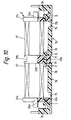
- the protrusions 24a, 24b and 24c may be omitted, if necessary. Further, since the grooves 75 are formed so as to penetrate partially the base members 7a and 7b (See Fig. 10), if sealing process of the structure with using resin for sealing the base members 7a, 7b and the cover 8 is employed, same resin adheres to the protrusions 22a, 22b and 22c to provide an additional fixening strength.
- the base member 7c has two contact members 70c and 70d.
- the member 70c includes a pair of movable contact springs 721a and 722a.
- the springs 721a and 722a have one ends fixed to common terminals 711a and 712a, and the other ends opposing to stationary contact terminals 73a and 74b, respectively.
- the common terminals 711a and 712a are connected together within the base member 7c and protrude from the bottom thereof as a single terminal. It is possible to regulate a contact pressure to be preliminarily applied to the contact springs 721a and 722a by twisting the respective common terminals 711a and 712a separately.
- a pair of slits may be formed in the actuating part 64 of the movable block 6 to form three-prolonged fork.
- the actuating part 64 comprises an outer stad 641, a center stad 642 and an inner stad 643 as mentioned with reference to Fig. 11.
- the stationary contact terminals 73a and 74a have stationary contacts 731 and 741, respectively, and the movable contact springs 721a and 722a have movable contacts 7211 and 7221, respectively.
- the springs 721a and 722a have contact pressures predetermined such that they are in contact with the terminals 73a and 74a, respectively.
- the stad 643 pushes the spring 722a so that the contacts 7221 and 741 are broken and the stad 642 pushes the spring 721a so that the contacts 7211 and 731 make (Fig. 12A).
- the magnet unit (not shown) is moved slightly by magnetic force in a direction E, so that the pushing forces of the stad 642 and 643 acting on the springs 721a and 722a are released. Then, due to the predetermined contact pressures, the contacts 741 and 7221 make together and the contacts 731 and 7211 are kept in contact (Fig. 12B).
Landscapes
- Physics & Mathematics (AREA)
- Electromagnetism (AREA)
- Electromagnets (AREA)
Claims (16)
- Relais électromagnétique polarisé comportant une paire d'unités d'aimant permanent (4, 5), chacune ayant un aimant permanent (43, 53) et une paire de plaques magnétiques (42, 42 ; 51, 52) fixées aux pôles magnétiques opposés de l'aimant permanent (43, 53), respectivement, un noyau de type barre (1), une carcasse (3) ayant des extrémités opposées, chaque extrémité formée par une paire respective des pièces d'extrémité opposée (31a, 31b ; 32a, 32b), une bobine (2) comportant un trou (24) formé longitudinalement dans celle-ci, le noyau (1) étant introduit à travers le trou (24), des rebords (21a, 21b, 21c) formés aux extrémités opposées et à une partie centrale de la bobine (2) respectivement, un bobinage (27) enroulé autour de la bobine (2) et une base (7a, 7b) comportant des éléments de contact (70a, 70b) sensibles aux unités d'aimant (4, 5), le relais électromagnétique polarisé étant caractérisé en ce que chacune des plaques magnétiques (41, 42, 51, 52) des unités d'aimant permanent (4, 5) est une plaque généralement en forme de U ayant une première extrémité (41a, 42a, 51a, 52a) et une seconde extrémité (41b, 42b, 51b, 52b), la première extrémité et la seconde extrémité de chacune des plaques magnétiques (41, 42, 51, 52) étant opposées lorsque fixées aux pôles de leurs aimants permanents respectifs (43, 53), en ce que la paire des unités d'aimant permanent (4, 5) est supportée par un élément de support (60) à ses extrémités opposées respectivement pour former un bloc mobile (6) pour commander les éléments de contact (70a, 70b) sensibles au déplacement des unités d'aimant permanent (4, 5), en ce que le noyau (1) comporte des extrémités opposées (1a, 1b) placées entre les premières extrémités (41a, 42a ; 51a, 52a) des plaques magnétiques (41, 42, 51, 52), respectivement, en ce que les secondes extrémités (41b, 42b, 51b, 52b) des plaques magnétiques sont disposées dans des espaces, chaque espace étant défini par les pièces d'extrémité opposée (31a, 31b ; 32a, 32b) de la carcasse (3), respectivement, en ce que la bobine (2) comporte de plus une multitude de protubérances (22A, 24a, 22b, 24b, 22c, 24c) dépassant vers l'extérieur sur les deux côtés de chacun des rebords (21a, 21b, 21c), en ce que la base (7a, 7b) est séparée en une paire d'éléments de base (7a, 7b), chaque élément de base comportant des rainures (75) et des évidements (77) pour recevoir les protubérances (22a, 24a, 22b, 24b, 22c, 24c) des rebords (21a, 21b, 21c) de la bobine (2), et en ce que des protubérances (76, 78) sont formées sur les surfaces latérales des parois intérieures de chacun des éléments de base (7a, 7b) pour mise en prise avec les protubérances (22a, 24a, 22b, 24b, 22c, 24c) de la bobine (2) par un déplacement longitudinal des éléments de base (7a, 7b) et des éléments de contact (70a, 70b) sensibles au bloc mobile (6), les éléments de base (7a, 7b) étant montés avec la bobine (2) à ses deux extrémités.
- Relais électromagnétique polarisé selon la revendication 1, comportant de plus des plaques résiduelles (44, 44a, 44b) d'un matériau non magnétique placées à l'intérieur des intervalles définis par les extrémités opposées (1a, 1b) du noyau (1) et les premières extrémités opposées (41a et 42a, 51a et 52a) des plaques magnétiques (41, 42, 51, 52) des unités d'aimant permanent (4, 5), respectivement.
- Relais électromagnétique polarisé selon la revendication 2, dans lequel les plaques résiduelles (44a, 44b) sont d'une épaisseur différente pour établir la résistance magnétique du circuit magnétique déséquilibré.
- Relais électromagnétique polarisé selon la revendication 3, comprenant de plus des plaques résiduelles (44a, 44b) ayant des épaisseurs différentes placées à l'intérieur des intervalles définis par des pièces d'extrémité (31a, 31b, 32a, 32b) de la carcasse (3) et les secondes extrémités (41b, 42b, 51b, 52b) des plaques magnétiques (41, 42, 51, 52) des unités d'aimant permanent (4, 5), respectivement.
- Relais électromagnétique polarisé selon la revendication 1, dans lequel les zones opposées des pièces d'extrémité (31a, 32b) de la carcasse (3) sont disposées diagonalement et les secondes extrémités (42b, 51b) des plaques magnétiques (42, 51) qui sont disposées diagonalement sont différentes des zones opposées des pièces d'extrémité restantes (31b, 32a) de la carcasse (3) qui sont disposées diagonalement et les extrémités restantes (41b, 52b) des plaques magnétiques (41, 52).
- Relais électromagnétique polarisé selon la revendication 1, dans lequel l'élément de contact (70c, 70d) d'au moins un des éléments de base (7c) comporte deux ressorts de contact mobile (721a, 722a) fixés à une borne commune (711a, 712a) sur sa première extrémité et opposés aux bornes de contact fixes différentes (73a, 74a) sur son autre extrémité.
- Relais électromagnétique polarisé selon la revendication 1, dans lequel l'élément de support (60) comporte des parties de support d'unité d'aimant (65) d'une résine isolante formée à ses extrémités opposées, une partie de raccord (62) d'une résine isolante pour raccorder les parties de support d'unités d'aimant et un cadre de renforcement non magnétique (63), les parties de support d'unités d'aimant et la partie de raccord étant formées sur le cadre de renforcement par moulage par insertion.
- Relais électromagnétique polarisé selon la revendication 7, dans lequel le cadre de renforcement est partiellement exposé dans la partie de raccord.
- Relais électromagnétique polarisé selon la revendication 7, dans lequel la partie de raccord comporte des première et seconde protubérances de palier (61a, 61b) dépassant horizontalement, et des troisième et quatrième protubérances de palier (61a, 61d) dépassant horizontalement dans le sens opposé aux première et seconde protubérances et dans lequel les rebords (21b) de la bobine (2) qui sont formées à son centre comportent des première et seconde broches (26a, 26b) dépassant vers le haut, les première et seconde broches (26a, 26b) étant disposées entre les première et seconde protubérances de palier (61a, 61b) et entre les troisième et quatrième protubérances de palier (61c, 61d) respectivement, pour former un arbre d'entraînement tournant du bloc mobile (6).
- Relais électromagnétique polarisé selon la revendication 1, dans lequel deux pièces d'extrémité (31a, 32b) de la carcasse (3) qui sont disposées diagonalement l'une par rapport à l'autre sont enlevées si bien que chacune des extrémités opposées de la carcasse (3) comporte seulement une pièce d'extrémité (31b, 32a).
- Relais électromagnétique polarisé selon la revendication 10, comprenant de plus des plaques résiduelles (44) d'un matériau non magnétique placées à l'intérieur d'intervalles définis par les extrémités opposées (1a, 1b) du noyau (1) et par les premières extrémités opposées (41a, 52a) des plaques magnétiques (41, 52) des unités d'aimant permanent (4, 5) sur le côté des pièces (31b, 32a) de la carcasse (3), respectivement.
- Relais électromagnétique polarisé selon la revendication 11, comportant de plus des plaques résiduelles (44) comportant des épaisseurs différentes placées à l'intérieur des intervalles définis par les pièces d'extrémité (31b, 32a) de la carcasse (3) et par les secondes extrémités (41b, 52b) des plaques magnétiques (41, 52) des unités d'aimant permanent (4, 5), respectivement.
- Relais électromagnétique polarisé selon la revendication 10, dans lequel l'élément de contact (70c, 70d) d'au moins un des éléments de base (7c) comporte deux ressorts de contact mobile (721a, 722a) fixés à une borne commune (711a, 712a) sur une de ses extrémité et opposés aux bornes de contact fixes différentes (73a, 74a) sur son autre extrémité.
- Relais électromagnétique polarisé selon la revendication 10, dans lequel l'élément de support (60) comporte des parties de support d'unités d'aimant (65) d'une résine isolante formées à ses extrémités opposées, une partie de raccord (62) d'une résine isolante pour raccorder les parties de support d'unités d'aimant et un cadre de renforcement non magnétique (63), les parties de support d'unités d'aimant et la partie de raccord étant formées sur le cadre de renforcement par insertion et moulage.
- Relais électromagnétique polarisé selon la revendication 14, dans lequel le cadre de renforcement est partiellement exposé dans la partie de raccord.
- Relais électromagnétique polarisé selon la revendication 14, dans lequel la partie de raccord comporte des première et seconde protubérances de palier (61a, 61b) dépassant horizontalement, et des troisième et quatrième protubérances de palier (61c, 61d) dépassant horizontalement dans un sens opposé aux première et seconde protubérances et dans lequel les rebords (21b) de la bobine (2) qui sont formées à son centre comportent des première et seconde broches (26a, 26b) dépassant vers le haut, les première et seconde broches (26a, 26b) étant disposées entre les première et seconde protubérances de palier (61a, 61b) et entre les troisième et quatrième protubérances de palier (61c, 61d), respectivement, pour former un arbre d'entraînement tournant du bloc mobile (6).
Applications Claiming Priority (10)
| Application Number | Priority Date | Filing Date | Title |
|---|---|---|---|
| JP164274/85 | 1985-10-25 | ||
| JP164276/85 | 1985-10-25 | ||
| JP16427685U JPS6271853U (fr) | 1985-10-25 | 1985-10-25 | |
| JP16427485U JPS6271851U (fr) | 1985-10-25 | 1985-10-25 | |
| JP164275/85 | 1985-10-25 | ||
| JP1985164275U JPH0446358Y2 (fr) | 1985-10-25 | 1985-10-25 | |
| JP115603/86 | 1986-05-19 | ||
| JP11560386A JPS62271317A (ja) | 1986-05-19 | 1986-05-19 | 有極電磁継電器 |
| JP75761/86 | 1986-05-19 | ||
| JP7576186U JPH0511628Y2 (fr) | 1986-05-19 | 1986-05-19 |
Publications (3)
| Publication Number | Publication Date |
|---|---|
| EP0225038A2 EP0225038A2 (fr) | 1987-06-10 |
| EP0225038A3 EP0225038A3 (en) | 1989-07-26 |
| EP0225038B1 true EP0225038B1 (fr) | 1992-09-23 |
Family
ID=27524588
Family Applications (1)
| Application Number | Title | Priority Date | Filing Date |
|---|---|---|---|
| EP86308273A Expired EP0225038B1 (fr) | 1985-10-25 | 1986-10-24 | Relais électromagnétique polarisé |
Country Status (4)
| Country | Link |
|---|---|
| US (1) | US4713638A (fr) |
| EP (1) | EP0225038B1 (fr) |
| CA (1) | CA1253182A (fr) |
| DE (1) | DE3686808T2 (fr) |
Families Citing this family (13)
| Publication number | Priority date | Publication date | Assignee | Title |
|---|---|---|---|---|
| DE3806806A1 (de) * | 1988-03-03 | 1989-09-14 | Standard Elektrik Lorenz Ag | Flachrelais, insbesondere miniatur-flachrelais |
| US4922217A (en) * | 1988-06-17 | 1990-05-01 | Hsc Controls, Inc. | Torque motor with magnet armature |
| US5070361A (en) * | 1990-11-30 | 1991-12-03 | General Electric Company | Molded case circuit breaker operating mechanism assembly |
| DE4300594A1 (de) * | 1993-01-13 | 1994-07-14 | Hengstler Bauelemente | Sicherheitsrelais mit zwangsgeführtem Kontaktsatz und monostabilem Antrieb |
| US6713753B1 (en) | 2001-07-03 | 2004-03-30 | Nanometrics Incorporated | Combination of normal and oblique incidence polarimetry for the characterization of gratings |
| JP4471859B2 (ja) * | 2005-01-31 | 2010-06-02 | 富士通コンポーネント株式会社 | 電磁継電器 |
| KR100795371B1 (ko) * | 2006-08-17 | 2008-01-17 | 삼성전기주식회사 | 선형 진동자 |
| US8514040B2 (en) * | 2011-02-11 | 2013-08-20 | Clodi, L.L.C. | Bi-stable electromagnetic relay with x-drive motor |
| CN102208305B (zh) * | 2011-05-19 | 2014-02-19 | 厦门宏发电声股份有限公司 | 一种极化继电器的磁路结构 |
| CN104813570A (zh) * | 2012-12-14 | 2015-07-29 | 武汉领普科技有限公司 | 永磁发电装置 |
| JP5835510B1 (ja) * | 2014-11-10 | 2015-12-24 | オムロン株式会社 | リレー |
| CN106712440B (zh) * | 2016-12-31 | 2019-07-26 | 武汉领普科技有限公司 | 发电装置 |
| US11501938B2 (en) * | 2019-07-09 | 2022-11-15 | Xiamen Hongfa Electroacoustic Co., Ltd. | Magnetic latching relay |
Family Cites Families (9)
| Publication number | Priority date | Publication date | Assignee | Title |
|---|---|---|---|---|
| US4563663A (en) * | 1982-07-16 | 1986-01-07 | Fujisoku Electric Co. Ltd. | Core member for an electromagnetic relay |
| JPS59166349U (ja) * | 1983-04-22 | 1984-11-07 | オムロン株式会社 | 有極電磁リレ− |
| JPS59171314U (ja) * | 1983-04-28 | 1984-11-16 | オムロン株式会社 | 電磁石装置 |
| DE3480625D1 (de) * | 1983-04-28 | 1990-01-04 | Omron Tateisi Electronics Co | Elektro-magnetisches relais mit symmetrischer rueckwirkung. |
| EP0130423A3 (fr) * | 1983-06-30 | 1985-09-18 | EURO-Matsushita Electric Works Aktiengesellschaft | Electro-aimant polarisé et son application dans un relais électromagnétique polarisé |
| EP0157029A1 (fr) * | 1984-04-04 | 1985-10-09 | Omron Tateisi Electronics Co. | Entraînement électromagnétique et relais polarisé |
| EP0168058B1 (fr) * | 1984-07-13 | 1992-01-02 | EURO-Matsushita Electric Works Aktiengesellschaft | Relais de sécurité |
| DE3425889C1 (de) * | 1984-07-13 | 1986-02-13 | SDS-Relais AG, 8024 Deisenhofen | Sicherheitsrelais |
| US4614927A (en) * | 1984-07-20 | 1986-09-30 | Nec Corporation | Polarized electromagnetic relay |
-
1986
- 1986-10-24 EP EP86308273A patent/EP0225038B1/fr not_active Expired
- 1986-10-24 US US06/923,087 patent/US4713638A/en not_active Expired - Fee Related
- 1986-10-24 CA CA000521309A patent/CA1253182A/fr not_active Expired
- 1986-10-24 DE DE8686308273T patent/DE3686808T2/de not_active Expired - Fee Related
Also Published As
| Publication number | Publication date |
|---|---|
| DE3686808D1 (de) | 1992-10-29 |
| US4713638A (en) | 1987-12-15 |
| CA1253182A (fr) | 1989-04-25 |
| EP0225038A2 (fr) | 1987-06-10 |
| EP0225038A3 (en) | 1989-07-26 |
| DE3686808T2 (de) | 1993-04-15 |
Similar Documents
| Publication | Publication Date | Title |
|---|---|---|
| EP0225038B1 (fr) | Relais électromagnétique polarisé | |
| US3993971A (en) | Electromagnetic relay | |
| EP0817230B1 (fr) | Contacteur électromagnétique | |
| EP0856865B1 (fr) | Relais électromagnétique | |
| US4626813A (en) | Electromagnetic drive and polarized relay | |
| JPH01231236A (ja) | 電磁スイッチ装置 | |
| EP0169714B1 (fr) | Relais électromagnétique polarisé | |
| EP0277833B1 (fr) | Relais électromagnétique polarisé | |
| EP0024216B1 (fr) | Relais électromagnétique du type inverseur | |
| US5162764A (en) | Slim-type polarized electromagnetic relay | |
| JP3826464B2 (ja) | 電磁継電器 | |
| JPH0260021A (ja) | 電磁継電器 | |
| JPH0440247Y2 (fr) | ||
| CA1037532A (fr) | Relais electromagnetique | |
| JP2533476Y2 (ja) | 電磁継電器 | |
| JPS6158217A (ja) | 有極電磁石 | |
| JPS61148803A (ja) | 電磁石装置用ヨ−ク | |
| JP2919443B2 (ja) | 電磁石装置 | |
| JPH0438495Y2 (fr) | ||
| CN121148954A (zh) | 继电器 | |
| JP3314974B2 (ja) | 有極リレー | |
| JP2687471B2 (ja) | 電磁継電器 | |
| JPH07296704A (ja) | 有極リレー | |
| JPS58209027A (ja) | 電磁リレ− | |
| JPH088045B2 (ja) | 有極形電磁石装置 |
Legal Events
| Date | Code | Title | Description |
|---|---|---|---|
| PUAI | Public reference made under article 153(3) epc to a published international application that has entered the european phase |
Free format text: ORIGINAL CODE: 0009012 |
|
| 17P | Request for examination filed |
Effective date: 19861031 |
|
| AK | Designated contracting states |
Kind code of ref document: A2 Designated state(s): DE FR GB |
|
| PUAL | Search report despatched |
Free format text: ORIGINAL CODE: 0009013 |
|
| AK | Designated contracting states |
Kind code of ref document: A3 Designated state(s): DE FR GB |
|
| 17Q | First examination report despatched |
Effective date: 19910524 |
|
| GRAA | (expected) grant |
Free format text: ORIGINAL CODE: 0009210 |
|
| AK | Designated contracting states |
Kind code of ref document: B1 Designated state(s): DE FR GB |
|
| REF | Corresponds to: |
Ref document number: 3686808 Country of ref document: DE Date of ref document: 19921029 |
|
| ET | Fr: translation filed | ||
| PLBE | No opposition filed within time limit |
Free format text: ORIGINAL CODE: 0009261 |
|
| STAA | Information on the status of an ep patent application or granted ep patent |
Free format text: STATUS: NO OPPOSITION FILED WITHIN TIME LIMIT |
|
| 26N | No opposition filed | ||
| PGFP | Annual fee paid to national office [announced via postgrant information from national office to epo] |
Ref country code: FR Payment date: 19931012 Year of fee payment: 8 |
|
| PGFP | Annual fee paid to national office [announced via postgrant information from national office to epo] |
Ref country code: GB Payment date: 19931015 Year of fee payment: 8 |
|
| PGFP | Annual fee paid to national office [announced via postgrant information from national office to epo] |
Ref country code: DE Payment date: 19931228 Year of fee payment: 8 |
|
| PG25 | Lapsed in a contracting state [announced via postgrant information from national office to epo] |
Ref country code: GB Effective date: 19941024 |
|
| GBPC | Gb: european patent ceased through non-payment of renewal fee |
Effective date: 19941024 |
|
| PG25 | Lapsed in a contracting state [announced via postgrant information from national office to epo] |
Ref country code: FR Effective date: 19950630 |
|
| PG25 | Lapsed in a contracting state [announced via postgrant information from national office to epo] |
Ref country code: DE Effective date: 19950701 |
|
| REG | Reference to a national code |
Ref country code: FR Ref legal event code: ST |