EP0225043A2 - Kabelverbindung - Google Patents
Kabelverbindung Download PDFInfo
- Publication number
- EP0225043A2 EP0225043A2 EP86308314A EP86308314A EP0225043A2 EP 0225043 A2 EP0225043 A2 EP 0225043A2 EP 86308314 A EP86308314 A EP 86308314A EP 86308314 A EP86308314 A EP 86308314A EP 0225043 A2 EP0225043 A2 EP 0225043A2
- Authority
- EP
- European Patent Office
- Prior art keywords
- cable
- conductor
- piercing member
- piezoelectric
- connection
- Prior art date
- Legal status (The legal status is an assumption and is not a legal conclusion. Google has not performed a legal analysis and makes no representation as to the accuracy of the status listed.)
- Granted
Links
- 239000004020 conductor Substances 0.000 claims abstract description 104
- 238000002844 melting Methods 0.000 claims abstract description 20
- 230000008018 melting Effects 0.000 claims abstract description 20
- 229910000679 solder Inorganic materials 0.000 claims abstract description 5
- 238000000034 method Methods 0.000 claims description 10
- 239000012772 electrical insulation material Substances 0.000 claims description 5
- 239000012774 insulation material Substances 0.000 claims description 4
- 238000010438 heat treatment Methods 0.000 claims description 3
- 230000000717 retained effect Effects 0.000 claims description 3
- 238000001816 cooling Methods 0.000 abstract description 2
- KRHYYFGTRYWZRS-UHFFFAOYSA-M Fluoride anion Chemical compound [F-] KRHYYFGTRYWZRS-UHFFFAOYSA-M 0.000 description 12
- 239000000463 material Substances 0.000 description 11
- 238000009413 insulation Methods 0.000 description 9
- 238000012360 testing method Methods 0.000 description 8
- RYGMFSIKBFXOCR-UHFFFAOYSA-N Copper Chemical compound [Cu] RYGMFSIKBFXOCR-UHFFFAOYSA-N 0.000 description 6
- 239000000853 adhesive Substances 0.000 description 6
- 230000001070 adhesive effect Effects 0.000 description 6
- 230000000694 effects Effects 0.000 description 6
- 229910052802 copper Inorganic materials 0.000 description 5
- 239000010949 copper Substances 0.000 description 5
- 229920000642 polymer Polymers 0.000 description 5
- 229910001369 Brass Inorganic materials 0.000 description 4
- 229910045601 alloy Inorganic materials 0.000 description 4
- 239000000956 alloy Substances 0.000 description 4
- 239000010951 brass Substances 0.000 description 4
- 239000000306 component Substances 0.000 description 4
- 229920001577 copolymer Polymers 0.000 description 4
- 230000004907 flux Effects 0.000 description 4
- 230000001681 protective effect Effects 0.000 description 4
- 239000007787 solid Substances 0.000 description 4
- 239000004677 Nylon Substances 0.000 description 3
- 238000003780 insertion Methods 0.000 description 3
- 230000037431 insertion Effects 0.000 description 3
- 239000002184 metal Substances 0.000 description 3
- 229910052751 metal Inorganic materials 0.000 description 3
- 229920001778 nylon Polymers 0.000 description 3
- 229920003023 plastic Polymers 0.000 description 3
- 239000004033 plastic Substances 0.000 description 3
- 229920002981 polyvinylidene fluoride Polymers 0.000 description 3
- 238000005476 soldering Methods 0.000 description 3
- 229910000881 Cu alloy Inorganic materials 0.000 description 2
- DGAQECJNVWCQMB-PUAWFVPOSA-M Ilexoside XXIX Chemical compound C[C@@H]1CC[C@@]2(CC[C@@]3(C(=CC[C@H]4[C@]3(CC[C@@H]5[C@@]4(CC[C@@H](C5(C)C)OS(=O)(=O)[O-])C)C)[C@@H]2[C@]1(C)O)C)C(=O)O[C@H]6[C@@H]([C@H]([C@@H]([C@H](O6)CO)O)O)O.[Na+] DGAQECJNVWCQMB-PUAWFVPOSA-M 0.000 description 2
- 239000002033 PVDF binder Substances 0.000 description 2
- BQCADISMDOOEFD-UHFFFAOYSA-N Silver Chemical compound [Ag] BQCADISMDOOEFD-UHFFFAOYSA-N 0.000 description 2
- 230000015572 biosynthetic process Effects 0.000 description 2
- 238000002788 crimping Methods 0.000 description 2
- 238000005755 formation reaction Methods 0.000 description 2
- 239000000543 intermediate Substances 0.000 description 2
- 238000011068 loading method Methods 0.000 description 2
- 229910001092 metal group alloy Inorganic materials 0.000 description 2
- 239000000203 mixture Substances 0.000 description 2
- -1 polyethylene Polymers 0.000 description 2
- 239000004800 polyvinyl chloride Substances 0.000 description 2
- 238000004382 potting Methods 0.000 description 2
- 229910052709 silver Inorganic materials 0.000 description 2
- 239000004332 silver Substances 0.000 description 2
- 229910052708 sodium Inorganic materials 0.000 description 2
- 239000011734 sodium Substances 0.000 description 2
- STBLNCCBQMHSRC-BATDWUPUSA-N (2s)-n-[(3s,4s)-5-acetyl-7-cyano-4-methyl-1-[(2-methylnaphthalen-1-yl)methyl]-2-oxo-3,4-dihydro-1,5-benzodiazepin-3-yl]-2-(methylamino)propanamide Chemical compound O=C1[C@@H](NC(=O)[C@H](C)NC)[C@H](C)N(C(C)=O)C2=CC(C#N)=CC=C2N1CC1=C(C)C=CC2=CC=CC=C12 STBLNCCBQMHSRC-BATDWUPUSA-N 0.000 description 1
- BQCIDUSAKPWEOX-UHFFFAOYSA-N 1,1-Difluoroethene Chemical compound FC(F)=C BQCIDUSAKPWEOX-UHFFFAOYSA-N 0.000 description 1
- KIKGHMPIMPPLCQ-UHFFFAOYSA-N 1,6-dichloro-3,3,4,4,5,6,6-heptafluorohex-1-ene Chemical compound FC(C(F)(F)Cl)C(C(C=CCl)(F)F)(F)F KIKGHMPIMPPLCQ-UHFFFAOYSA-N 0.000 description 1
- XFXPMWWXUTWYJX-UHFFFAOYSA-N Cyanide Chemical compound N#[C-] XFXPMWWXUTWYJX-UHFFFAOYSA-N 0.000 description 1
- 239000004593 Epoxy Substances 0.000 description 1
- 229920000571 Nylon 11 Polymers 0.000 description 1
- 239000004698 Polyethylene Substances 0.000 description 1
- 230000002411 adverse Effects 0.000 description 1
- 230000032683 aging Effects 0.000 description 1
- 125000004432 carbon atom Chemical group C* 0.000 description 1
- 229910010293 ceramic material Inorganic materials 0.000 description 1
- UUAGAQFQZIEFAH-UHFFFAOYSA-N chlorotrifluoroethylene Chemical group FC(F)=C(F)Cl UUAGAQFQZIEFAH-UHFFFAOYSA-N 0.000 description 1
- 239000011248 coating agent Substances 0.000 description 1
- 238000000576 coating method Methods 0.000 description 1
- 229940125878 compound 36 Drugs 0.000 description 1
- 238000010276 construction Methods 0.000 description 1
- 238000001514 detection method Methods 0.000 description 1
- 230000001627 detrimental effect Effects 0.000 description 1
- 239000006023 eutectic alloy Substances 0.000 description 1
- 230000005496 eutectics Effects 0.000 description 1
- 230000001747 exhibiting effect Effects 0.000 description 1
- XUCNUKMRBVNAPB-UHFFFAOYSA-N fluoroethene Chemical compound FC=C XUCNUKMRBVNAPB-UHFFFAOYSA-N 0.000 description 1
- 230000006698 induction Effects 0.000 description 1
- 239000011810 insulating material Substances 0.000 description 1
- 238000012423 maintenance Methods 0.000 description 1
- 239000011159 matrix material Substances 0.000 description 1
- 238000012986 modification Methods 0.000 description 1
- 230000004048 modification Effects 0.000 description 1
- 239000003973 paint Substances 0.000 description 1
- 238000010587 phase diagram Methods 0.000 description 1
- 229920001084 poly(chloroprene) Polymers 0.000 description 1
- 239000005015 poly(hydroxybutyrate) Substances 0.000 description 1
- 229920003229 poly(methyl methacrylate) Polymers 0.000 description 1
- 229920000573 polyethylene Polymers 0.000 description 1
- 239000004926 polymethyl methacrylate Substances 0.000 description 1
- 229920000915 polyvinyl chloride Polymers 0.000 description 1
- 239000000843 powder Substances 0.000 description 1
- 238000011084 recovery Methods 0.000 description 1
- 230000035939 shock Effects 0.000 description 1
- 238000010561 standard procedure Methods 0.000 description 1
- 230000002311 subsequent effect Effects 0.000 description 1
- 229920001897 terpolymer Polymers 0.000 description 1
- 238000005382 thermal cycling Methods 0.000 description 1
- 239000011800 void material Substances 0.000 description 1
Images
Classifications
-
- H—ELECTRICITY
- H01—ELECTRIC ELEMENTS
- H01R—ELECTRICALLY-CONDUCTIVE CONNECTIONS; STRUCTURAL ASSOCIATIONS OF A PLURALITY OF MUTUALLY-INSULATED ELECTRICAL CONNECTING ELEMENTS; COUPLING DEVICES; CURRENT COLLECTORS
- H01R43/00—Apparatus or processes specially adapted for manufacturing, assembling, maintaining, or repairing of line connectors or current collectors or for joining electric conductors
- H01R43/02—Apparatus or processes specially adapted for manufacturing, assembling, maintaining, or repairing of line connectors or current collectors or for joining electric conductors for soldered or welded connections
-
- H—ELECTRICITY
- H10—SEMICONDUCTOR DEVICES; ELECTRIC SOLID-STATE DEVICES NOT OTHERWISE PROVIDED FOR
- H10N—ELECTRIC SOLID-STATE DEVICES NOT OTHERWISE PROVIDED FOR
- H10N30/00—Piezoelectric or electrostrictive devices
- H10N30/60—Piezoelectric or electrostrictive devices having a coaxial cable structure
-
- H—ELECTRICITY
- H01—ELECTRIC ELEMENTS
- H01R—ELECTRICALLY-CONDUCTIVE CONNECTIONS; STRUCTURAL ASSOCIATIONS OF A PLURALITY OF MUTUALLY-INSULATED ELECTRICAL CONNECTING ELEMENTS; COUPLING DEVICES; CURRENT COLLECTORS
- H01R4/00—Electrically-conductive connections between two or more conductive members in direct contact, i.e. touching one another; Means for effecting or maintaining such contact; Electrically-conductive connections having two or more spaced connecting locations for conductors and using contact members penetrating insulation
- H01R4/02—Soldered or welded connections
-
- H—ELECTRICITY
- H01—ELECTRIC ELEMENTS
- H01R—ELECTRICALLY-CONDUCTIVE CONNECTIONS; STRUCTURAL ASSOCIATIONS OF A PLURALITY OF MUTUALLY-INSULATED ELECTRICAL CONNECTING ELEMENTS; COUPLING DEVICES; CURRENT COLLECTORS
- H01R4/00—Electrically-conductive connections between two or more conductive members in direct contact, i.e. touching one another; Means for effecting or maintaining such contact; Electrically-conductive connections having two or more spaced connecting locations for conductors and using contact members penetrating insulation
- H01R4/58—Electrically-conductive connections between two or more conductive members in direct contact, i.e. touching one another; Means for effecting or maintaining such contact; Electrically-conductive connections having two or more spaced connecting locations for conductors and using contact members penetrating insulation characterised by the form or material of the contacting members
-
- H—ELECTRICITY
- H01—ELECTRIC ELEMENTS
- H01R—ELECTRICALLY-CONDUCTIVE CONNECTIONS; STRUCTURAL ASSOCIATIONS OF A PLURALITY OF MUTUALLY-INSULATED ELECTRICAL CONNECTING ELEMENTS; COUPLING DEVICES; CURRENT COLLECTORS
- H01R9/00—Structural associations of a plurality of mutually-insulated electrical connecting elements, e.g. terminal strips or terminal blocks; Terminals or binding posts mounted upon a base or in a case; Bases therefor
- H01R9/03—Connectors arranged to contact a plurality of the conductors of a multiconductor cable, e.g. tapping connections
- H01R9/05—Connectors arranged to contact a plurality of the conductors of a multiconductor cable, e.g. tapping connections for coaxial cables
-
- Y—GENERAL TAGGING OF NEW TECHNOLOGICAL DEVELOPMENTS; GENERAL TAGGING OF CROSS-SECTIONAL TECHNOLOGIES SPANNING OVER SEVERAL SECTIONS OF THE IPC; TECHNICAL SUBJECTS COVERED BY FORMER USPC CROSS-REFERENCE ART COLLECTIONS [XRACs] AND DIGESTS
- Y10—TECHNICAL SUBJECTS COVERED BY FORMER USPC
- Y10T—TECHNICAL SUBJECTS COVERED BY FORMER US CLASSIFICATION
- Y10T29/00—Metal working
- Y10T29/49—Method of mechanical manufacture
- Y10T29/49002—Electrical device making
- Y10T29/49117—Conductor or circuit manufacturing
- Y10T29/49174—Assembling terminal to elongated conductor
- Y10T29/49179—Assembling terminal to elongated conductor by metal fusion bonding
Definitions
- This invention relates to a cable connection, and particularly, though not exclusively to connection to a coaxial cable, which may be a piezoelectric cable.
- piezoelectric cable that comprises a central stretchable electrical conductor, a piezoelectric intermediate layer, and an outer electrical conductor.
- the intermediate layer is formed from polyvinylidine fluoride that has been axially stretched and radially polarized to render it piezoelectric.
- the central conductor is preferably formed from a low melting point metal alloy, and is thus itself in the nature of a solder.
- Difficulties may be experienced when making an electrical connection to such a cable, and in particular to the central conductor, due to the mechanical softness and low melting point of the conductor, and the susceptibility of the piezoelectric insulation material to creeping, due to the fact that it is stretched but not cross-linked.
- crimping techniques or potting with an electrically conductive adhesive may not always give satisfactory results.
- the insulating material is much stronger than the inner conductor, it can be difficult in any case to strip the insulation without removing part of the inner conductor at the same time.
- a method of forming an electrical connection to an electric cable having a conductor surrounded by electrical insulation material wherein (i) a conductive piercing member is inserted into the conductor so as to leave a portion of the piercing member extending from the cable, (ii) the piercing member is heated to at least the softening temperature of the conductor, thereby to produce local softening of the conductor, and (iii) allowing the piercing member and the conductor to cool, to form a solder joint therebetween.
- soldered joint It has been found advantageous to achieve a soldered joint in order to ensure low resistance at the connection and to ensure maintenance of the connection under tension and vibration.
- a good soldered joint is obtained when an intermetallic interference layer of about one micron thickness is formed between the two materials being connected together.
- the heating of the piercing member is effected before it is inserted into the conductor, so that pressure of the hot piercing member on the conductor allows local softening of the conductor and facilitates insertion of the piercing member.
- the piercing member and conductor may be such that the piercing member may be inserted into the conductor, with heat subsequently being applied to the piercing member, by conduction or induction heating for example, to effect the local softening and subsequent soldering.
- Electric cables having sodium as a conductor, which has a melting point of 97.8°C, are known, for example from British Patent Specification No. 1234159, whereby connection is made to the conductor by means of a tapered copper conducting member that is forced axially into the sodium. The connection is subsequently sealed within a heat shrinkable plastics insulating tube. However, no heat is applied to effect softening of the conductor to produce a soldered connection.
- the heated piercing member softens and may even melt the conductor at least locally, and so can be introduced into the cable, preferably longitudinally of the conductor, for a length sufficient to ensure good electrical contact between the piercing member and the conductor, that is to say, with low electrical contact resistance therebetween.
- the piercing member will be sufficently rigid at the softening or melting temperature of the conductor for such insertion to take place.
- the temperature should clearly not be so high that the cable insulation or other components are damaged thereby.
- the cable may be a piezoelectric cable, that is to say a cable having a dielectric with piezoelectric properties.
- the piercing member extending from the cable conductor can then be connected to another cable, which may or may not be of the same configuration as said cable, or to a cable connector as required, by any suitable means, which may be any of the conventional conductor connection means such as soldering or crimping.
- the piercing member may be a short pin, or may be an elongate conductor.
- an electric cable comprising a conductor surrounded by electrical insulation material, and a piercing member retained within the conductor and extending from the cable, wherein the softening temperature of the conductor is below that of the piercing member, and the conductor and piercing member are soldered together.
- the conductor comprises a low melting point metal alloy.
- the conductor has a melting point of not more than 170°C, more preferably not more than 160°C, and most preferably not more than 150°C.
- the conductor it is preferred for the conductor to have a melting point of at least 50°C, more preferably at least 60°C, particularly at least 65°C and most preferably at least 70°C.
- the conductor may be formed from an alloy having a eutectic composition, thus exhibiting a single, well-defined melting point, but it may also be formed from a non-eutectic alloy, thus entering a phase between the solidus and liquidus lines of its phase diagram in which its ductility increases with temperature.
- the conductor does not need to melt completely, or even at all, in order that the piercing member can be inserted therein, but it must become sufficiently soft to allow this to occur.
- the conductor advantageously should not fracture. Should fracture occur, either during the stretching operation that is used in the cable formation, described in the above-mentioned publications, or during insertion of the piercing member, voids may appear.
- voids are generally undesirable, it will be appreconstrumerelyciated that the present invention allows their adverse effect on electrical contact to be overcome, at least to an appreciable extent.
- the electrical contact between the piercing member and the conductor can conveniently extend over a significant distance, say up to 10 mm, so that the effect of voids occurring locally may be negligible on the contact resistance. It will be noted that this may not be so with a crimp connection, which unknowingly could be made at a part of the cable that contains a significantly large void.
- Electrical contact with the cable conductor can be further improved by coating the relatively high melting point material, such as high strength copper alloy, of the piercing member with the same material as that used for the conductor, thus acting as a flux. In this case, the fluxed piercing member may be heated until the flux is seen to start to melt, thus conveniently indicating that the member has reached a high enough temperature to allow it to penetrate the soft conductor of the cable.
- Examples of low melting point alloys that may be used for the conductor are shown in Table 1.
- the piercing member will be smaller than the conductor, and where these are of circular cross-section, typically the diameter of the conductor may be about twice that of the piercing member.
- the insulation material may be piezoelectric material.
- Such piezoelectric material may include nylon materials having an odd number of carbon atoms, especially nylon 5, nylon 7, and nylon 11, polyhydroxybutyrate, vinylidine cyanide/vinyl acetate copolymers and vinylidine fluoride polymers.
- the term "vinylidine fluoride polymer” is intended to include polyvinylidine fluoride, commonly abbreviated to "PVDF” or "PVF2" and those copolymers of vinylidine fluoride in which a piezoelectric activity may be generated or enhanced by orientation.
- Suitable copolymers include copolymers and terpolymers of vinylidine fluoride with vinyl fluoride, trifluoroethylene, tetrafluoroethylene, vinyl chloride, and chlorotrifluoroethylene.
- blends of vinylidine fluoride polymers with other polymers, e.g. polymethylmethacrylate, are included provided that the piezoelectric activity thereof is not destroyed.
- the piezoelectric material comprises a vinylidine fluoride polymer, more preferably polyvinylidine fluoride and especially it consists substantially solely of polyvinylidine fluoride.
- piezo-polymeric materials are suitable, but also piezo ceramic materials, such as those disclosed in UK Patent No 2012519, dispersed as a powder in a matrix of polymer, such as neoprene.
- the cable may be of generally coaxial configuration, and electrical connection may be made to the outer conductor as required.
- the cable may be a coaxial piezoelectric cable. More particularly the cable piezoelectric material may be PVDF or a similar material as described above, and the inner conductor may be a low melting point alloy.
- the advantages of a cable that can be screened against electromagnetic interference are very conveniently combined with a cable having piezoelectric properties, useful for intruder alarms or the like for example.
- low melting point is understood to mean that the melting point of the conductor is lower than the melting or softening point of the insulation of the cable.
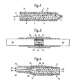
- a piezoelectric coaxial cable 2 comprises an inner conductor 4 formed from one of the alloys given in Table 1, an insulating layer 6 formed from polyvinylidine fluoride, an outer conductive layer 8 formed from silver paint, and an outer protective heat shrinkable polymeric jacket 10 formed from polyethylene.
- the cable 2 may optionally be provided along its length with an outer polymeric jacket on top of its outer electrode 8, such jacket being formed from polyvinylidine fluoride, polyethylene, ethylene vinyl acetate copolymers and the like.
- the outer electrode 8 has been removed to expose a portion of the insulating layer 6. However, because of the brittle nature of the inner conductor 4, the insulating layer 6 has been left intact so that only the face of the conductor 4 at the end of the cable 2 is exposed.
- the outer diameter of the outer conductor 8 is about 1.5 mm, and the diameter of the solid inner conductor 4 is about 0.5 mm.
- a high strength solid copper alloy wire 12 of 0.2 mm to 0.25 mm diameter is coated at one end 14 with a flux layer of the low melting point material used to form the inner cable electrode 4.
- the wire end 14 is heated to a temperature at which the flux is seen to start to melt, such that it can be inserted longitudinally into the inner conductor 4 of the cable 2 for a distance of 3 mm to 5 mm from its exposed end face by causing local melting of the conductor 4 around the wire end 14.
- a portion of cable similar to the cable 2 of Figure 1 was subjected to a cyclical ageing test during which the cable was maintained at -55°C, for one hour, raised to +75°C in about 20 seconds, and maintained at the higher temperature for a further hour. After this cycle, cooling was quickly effected to -55°C, and the cycle repeated.
- the resistance of the inner conductor 4 and the inserted wire 12 over a 50 mm length from a point X ( Figure 1) just outside the cable to a point Y at the other end was measured at the start, after 66 cycles, and again after 86 cycles. This was done for eight samples, and the test results are given in Table 2 below.
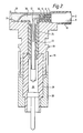
- the cable 2 of Figure 1 is shown in Figure 2 with a connector 16 attached thereto.
- the connector 16 comprises an elongate brass housing 18 and a cover 20 that fits thereinto, and is so arranged that an L-shaped connection is formed to the cable 2.
- the cable 2 is arranged to sit in the housing 16 with the flexible wire 12 bent through 90° of arc after leaving the conductor 4 and is crimped and/or soldered into a hollow brass pin 22 that is located in an insulating plastics liner 24 mounted in the housing 18.
- the pin 22 engages with a further electrical contact 26 that extends from the housing 18 and that is retained with an insulating plastics insert 28 within an end portion 30 of the brass housing 18.
- a stranded copper conductor 32 is connected at one end to the outer conductor 8 of the piezoelectric cable 2 by a silver coated adhesive, and extends into the connector 16 to be soldered at 34 to the brass housing 18.
- the space within the connector 16 around the conductors 12 and 32, and around the end face of the cable 2 is filled with an electrically insulating potting compound 36.
- the connector lid 20 is placed into its recess in the housing 18, which is then flanged over, thereby securely clamping the cable 2 within the connector 16. Accordingly, not only is strain relief provided for connection to the cable 2, but the cable 2 can now be conveniently and safely connected into an electrical circuit or to other electrical equipment.
- the connector contact 26 and housing 18, insulated from each other by the components 22 and 28, continue the electrical paths from the inner and outer conductors 4 and 8 respectively of the piezoelectric cable 2.
- the connector 16 may be plugged in to other equipment, or electricial leads may be taken therefrom to a printed circuit board, for example flexprint, as required.
- a cable such as cable 2 is in an intruder alarm, and the connector 16 may be connected to a suitable detection circuit.
- a piezoelectric coax cable 40 of the same configuration as cable 2 has a copper wire 42 extending from an inner electrode (not shown) thereof.
- the wire 42 is soldered at 44 to the extended central conductor 46 of a further coax cable 48.
- the coax cable 48 and the conductor 46 may correspond to the cable 40 and wire 42, but may alternatively be a standard coax cable wherein the conductor 46 is an extension of the solid copper conductor thereof.
- An inner metal tube 50 surrounds the soldered joint 44, and the space therewithin is filled with adhesive.
- the tube 50 is then enclosed with an insulating heat shrinkable polymeric sleeve 52.
- An outer metal tube 54 extends between the outer electrodes of the cables 40 and 48 to continue the shielding therebetween, and this is enclosed within a further insulating heat shrinkable polymeric sleeve 56 to complete the cable splice.
- Figure 4 shows a further splice involving a coax cable 70, which may be a piezoelectric cable, that has a high strength conductor 72 soldered into a low melting point inner conductor 74.
- the cable outer conductor 76 is cut back to expose an end of the cable insulation 78. It is required to splice the conductors of the cable 70 to respective conductors of two single wire cables 80 and 82.
- the cable 80 comprises a solid copper conductor 84 enclosed within and extending from polyvinylchloride (PVC) insulation 86.
- the conductors 72 and 84 are soldered together and encased within an epoxy insulating adhesive.
- a heat shrinkable insulating polymeric protective sleeve 88 is recovered over the solder joint, and extends on to the insulation 78 and 86 of the cables 70 and 80 respectively.
- the cable 82 comprises a stranded copper conductor 90 and PVC insulation 92.
- the conductor 90 is exposed at one end of the cable 82 and the strands are splayed out and secured by adhesive around about 50% of the curved surface of the outer conductor 76 of the coax cable 70.
- the splice is completed by recovery of an outer heat shrinkable insulating polymeric sleeve 94 that extends around the outer conductor 76 (and any outermost protective cable jacket thereon) of the coax cable 70, across the soldered and adhesive joints, and around the insulating jackets of each of the cables 80 and 82, thereby to provide electrical protection and mechanical protection, including strain relief, of the cable connections.
Landscapes
- Engineering & Computer Science (AREA)
- Manufacturing & Machinery (AREA)
- Connections Effected By Soldering, Adhesion, Or Permanent Deformation (AREA)
- Cable Accessories (AREA)
- Multi-Conductor Connections (AREA)
- Manufacturing Of Electrical Connectors (AREA)
- Insulated Conductors (AREA)
Priority Applications (1)
| Application Number | Priority Date | Filing Date | Title |
|---|---|---|---|
| AT86308314T ATE80504T1 (de) | 1985-10-25 | 1986-10-24 | Kabelverbindung. |
Applications Claiming Priority (2)
| Application Number | Priority Date | Filing Date | Title |
|---|---|---|---|
| GB8526377 | 1985-10-25 | ||
| GB858526377A GB8526377D0 (en) | 1985-10-25 | 1985-10-25 | Cable connection |
Publications (3)
| Publication Number | Publication Date |
|---|---|
| EP0225043A2 true EP0225043A2 (de) | 1987-06-10 |
| EP0225043A3 EP0225043A3 (en) | 1988-07-27 |
| EP0225043B1 EP0225043B1 (de) | 1992-09-09 |
Family
ID=10587256
Family Applications (1)
| Application Number | Title | Priority Date | Filing Date |
|---|---|---|---|
| EP86308314A Expired - Lifetime EP0225043B1 (de) | 1985-10-25 | 1986-10-24 | Kabelverbindung |
Country Status (7)
| Country | Link |
|---|---|
| US (1) | US4786760A (de) |
| EP (1) | EP0225043B1 (de) |
| JP (1) | JPS62100964A (de) |
| AT (1) | ATE80504T1 (de) |
| CA (1) | CA1264074A (de) |
| DE (1) | DE3686703T2 (de) |
| GB (1) | GB8526377D0 (de) |
Families Citing this family (37)
| Publication number | Priority date | Publication date | Assignee | Title |
|---|---|---|---|---|
| US5403201A (en) * | 1993-08-16 | 1995-04-04 | Mccarthy; Dale C. | Electrical connector |
| US6126491A (en) * | 1996-05-14 | 2000-10-03 | Centerpin Technology, Inc. | Electrical connector apparatus and method |
| US6848934B1 (en) | 1996-05-14 | 2005-02-01 | Centerpin Technology, Inc. | Battery terminal |
| US5704814A (en) * | 1996-05-14 | 1998-01-06 | Centerpin Technology, Inc. | Electrical connector |
| US6244892B1 (en) | 1996-05-14 | 2001-06-12 | Centerpin Technology, Inc. | Electrical connector apparatus and method |
| US6123567A (en) * | 1996-05-15 | 2000-09-26 | Centerpin Technology, Inc. | Coaxial cable connector |
| US5775934A (en) * | 1996-05-15 | 1998-07-07 | Centerpin Technology, Inc. | Coaxial cable connector |
| FR2769419B1 (fr) * | 1997-10-07 | 2003-05-23 | Alsthom Cge Alkatel | Dispositif de protection etanche pour une jonction de cables haute tension |
| US6705884B1 (en) | 1999-08-16 | 2004-03-16 | Centerpin Technology, Inc. | Electrical connector apparatus and method |
| AU2000267992A1 (en) * | 2000-08-23 | 2002-03-04 | John K Shannon | Solder-in-place axial-type connector |
| ATE323943T1 (de) * | 2003-07-02 | 2006-05-15 | Abb Research Ltd | Kraftübertragungselement, verfahren zu dessen herstellung und vorrichtung zur durchführung des verfahrens |
| EP2137375A4 (de) | 2007-04-20 | 2015-11-18 | Shell Int Research | In-situ-wiederherstellung restlicher erhitzter bereiche in einer kohlenwasserstoffhaltigen formation |
| US20110021069A1 (en) * | 2009-07-21 | 2011-01-27 | Yiping Hu | Thin format crush resistant electrical cable |
| WO2011032127A2 (en) | 2009-09-14 | 2011-03-17 | Roger Faulkner | Underground modular high-voltage direct current electric power transmission system |
| US9466896B2 (en) * | 2009-10-09 | 2016-10-11 | Shell Oil Company | Parallelogram coupling joint for coupling insulated conductors |
| US8257112B2 (en) | 2009-10-09 | 2012-09-04 | Shell Oil Company | Press-fit coupling joint for joining insulated conductors |
| US8485256B2 (en) | 2010-04-09 | 2013-07-16 | Shell Oil Company | Variable thickness insulated conductors |
| US8586866B2 (en) | 2010-10-08 | 2013-11-19 | Shell Oil Company | Hydroformed splice for insulated conductors |
| US8857051B2 (en) | 2010-10-08 | 2014-10-14 | Shell Oil Company | System and method for coupling lead-in conductor to insulated conductor |
| US8943686B2 (en) | 2010-10-08 | 2015-02-03 | Shell Oil Company | Compaction of electrical insulation for joining insulated conductors |
| US8572838B2 (en) | 2011-03-02 | 2013-11-05 | Honeywell International Inc. | Methods for fabricating high temperature electromagnetic coil assemblies |
| JP2014512082A (ja) | 2011-04-08 | 2014-05-19 | シエル・インターナシヨナル・リサーチ・マートスハツペイ・ベー・ヴエー | 絶縁導体を接合するシステム |
| US8466767B2 (en) | 2011-07-20 | 2013-06-18 | Honeywell International Inc. | Electromagnetic coil assemblies having tapered crimp joints and methods for the production thereof |
| US9108348B2 (en) | 2011-10-03 | 2015-08-18 | Commscope Technologies Llc | Method for molding a low pressure molded strain relief for coaxial connector interconnection |
| JO3139B1 (ar) | 2011-10-07 | 2017-09-20 | Shell Int Research | تشكيل موصلات معزولة باستخدام خطوة اختزال أخيرة بعد المعالجة الحرارية. |
| JO3141B1 (ar) | 2011-10-07 | 2017-09-20 | Shell Int Research | الوصلات المتكاملة للموصلات المعزولة |
| US9080917B2 (en) | 2011-10-07 | 2015-07-14 | Shell Oil Company | System and methods for using dielectric properties of an insulated conductor in a subsurface formation to assess properties of the insulated conductor |
| US8860541B2 (en) | 2011-10-18 | 2014-10-14 | Honeywell International Inc. | Electromagnetic coil assemblies having braided lead wires and methods for the manufacture thereof |
| US9076581B2 (en) | 2012-04-30 | 2015-07-07 | Honeywell International Inc. | Method for manufacturing high temperature electromagnetic coil assemblies including brazed braided lead wires |
| US8754735B2 (en) | 2012-04-30 | 2014-06-17 | Honeywell International Inc. | High temperature electromagnetic coil assemblies including braided lead wires and methods for the fabrication thereof |
| US9027228B2 (en) | 2012-11-29 | 2015-05-12 | Honeywell International Inc. | Method for manufacturing electromagnetic coil assemblies |
| US9722464B2 (en) | 2013-03-13 | 2017-08-01 | Honeywell International Inc. | Gas turbine engine actuation systems including high temperature actuators and methods for the manufacture thereof |
| JP5608842B1 (ja) * | 2013-05-28 | 2014-10-15 | 株式会社フジクラ | 線材接続装置、線材接続方法、及び接続構造体の製造方法 |
| CN103326142B (zh) * | 2013-06-09 | 2015-08-12 | 北京依米康科技发展有限公司 | 一种低熔点金属电缆接续装置 |
| DE102015102703B4 (de) | 2015-02-25 | 2020-06-25 | Phoenix Contact Gmbh & Co. Kg | Geschirmter elektrischer Steckverbinder und Herstellungsverfahren |
| CN104868265B (zh) * | 2015-05-08 | 2017-03-08 | 黄河勘测规划设计有限公司 | 自愈式铜芯电缆中间接头 |
| CN109473788B (zh) * | 2018-12-25 | 2024-11-05 | 广州电缆厂有限公司 | 一种多点接线用强化电线 |
Family Cites Families (13)
| Publication number | Priority date | Publication date | Assignee | Title |
|---|---|---|---|---|
| US2970184A (en) * | 1958-03-05 | 1961-01-31 | Blonder Tongue Elect | Electric cable connector |
| DE1276155B (de) * | 1962-11-22 | 1968-08-29 | Siemens Ag | Anordnung zum elektrischen Anschliessen isolierter elektrischer Leiter geringen Querschnittes |
| GB1234159A (de) * | 1969-01-29 | 1971-06-03 | ||
| GB1470049A (en) * | 1973-03-21 | 1977-04-14 | Rachem Corp | Splicing method and heat-recoverable article |
| US3970862A (en) * | 1974-06-25 | 1976-07-20 | The United States Of America As Represented By The Secretary Of The Navy | Polymeric sensor of vibration and dynamic pressure |
| DE2443656A1 (de) * | 1974-09-12 | 1976-03-25 | Interatom | Kabelverbindung |
| US3951503A (en) * | 1974-11-04 | 1976-04-20 | Caulkins Robert M | Cable splice assembly for multiconductor cables |
| GB2012519A (en) * | 1978-01-17 | 1979-07-25 | Atomic Energy Authority Uk | Piezoelectric devices |
| US4339683A (en) * | 1980-02-04 | 1982-07-13 | The United States Of America As Represented By The Secretary Of The Navy | Electrical connection |
| US4450318A (en) * | 1981-09-29 | 1984-05-22 | Siemens-Allis, Inc. | Means and method for providing insulation splice |
| US4629925A (en) * | 1983-11-22 | 1986-12-16 | Raychem Corporation | Piezoelectric coaxial cable |
| EP0146272A3 (de) * | 1983-11-22 | 1988-03-16 | Focas Limited | Koaxiales Kabel |
| US4609845A (en) * | 1984-07-06 | 1986-09-02 | Raychem Corporation | Stretched piezoelectric polymer coaxial cable |
-
1985
- 1985-10-25 GB GB858526377A patent/GB8526377D0/en active Pending
-
1986
- 1986-10-20 US US06/921,172 patent/US4786760A/en not_active Expired - Fee Related
- 1986-10-24 DE DE8686308314T patent/DE3686703T2/de not_active Expired - Fee Related
- 1986-10-24 AT AT86308314T patent/ATE80504T1/de not_active IP Right Cessation
- 1986-10-24 EP EP86308314A patent/EP0225043B1/de not_active Expired - Lifetime
- 1986-10-24 CA CA000521349A patent/CA1264074A/en not_active Expired
- 1986-10-25 JP JP61254574A patent/JPS62100964A/ja active Pending
Also Published As
| Publication number | Publication date |
|---|---|
| GB8526377D0 (en) | 1985-11-27 |
| JPS62100964A (ja) | 1987-05-11 |
| US4786760A (en) | 1988-11-22 |
| EP0225043B1 (de) | 1992-09-09 |
| DE3686703D1 (de) | 1992-10-15 |
| DE3686703T2 (de) | 1993-04-22 |
| EP0225043A3 (en) | 1988-07-27 |
| CA1264074A (en) | 1989-12-27 |
| ATE80504T1 (de) | 1992-09-15 |
Similar Documents
| Publication | Publication Date | Title |
|---|---|---|
| EP0225043B1 (de) | Kabelverbindung | |
| EP2192601B1 (de) | Kabelbaum und verfahren zu seiner herstellung | |
| US5393932A (en) | Wire connector | |
| EP0707321B1 (de) | Litzenleiter mit verfestigtem Ende | |
| US4317277A (en) | Low resistance electric joint between conductive members, at least one member having an insulation coating thereon, and the method of making such joint | |
| EP0330357A1 (de) | Ein mit einer Anschlussklemme versehenes elektrisches Koaxialkabel und Verfahren zu dessen Herstellung | |
| US4894906A (en) | Superconductive joint for multifilament superconducting and method of forming | |
| US5369225A (en) | Wire connector | |
| EP0660970B1 (de) | Anschlussvorrichtung und verfahren | |
| US5537742A (en) | Method for joining multiple conductor cables | |
| EP0261905A2 (de) | Elektrischer Verbinder und Verfahren zur Verbindung von Adern an diesem | |
| US4949454A (en) | Method for making an electrical connection to a flat electrical conductor | |
| WO2013032030A1 (en) | Electric cable end processing method and electric cable end structure with solder coating and sheath protection | |
| JPS63318082A (ja) | ケーブル接続部形成方法およびそのためのアレンジメント | |
| CA1294682C (en) | Electrical connector | |
| EP0626101B1 (de) | Kabelverbinder | |
| KR20010110125A (ko) | 땜납 용착물이 있는 납땜 가능한 전기적 연결 요소 | |
| US4707566A (en) | Electrical crimp connection | |
| JP2013020761A (ja) | アルミリッツ線の端子接続方法及び端子接続部 | |
| JP3214703B2 (ja) | 電気コネクター | |
| JP6941731B2 (ja) | 電気デバイス用の撚り線コネクタ及び撚り線コネクタの製造方法 | |
| CN209993731U (zh) | 双金属端部套筒 | |
| JP2004311208A (ja) | 電線 | |
| EP0091319A1 (de) | Vorrichtung zum Verbinden einer Abschirmung | |
| KR101989569B1 (ko) | 극세선 번들의 열선과 전선의 접속방법 |
Legal Events
| Date | Code | Title | Description |
|---|---|---|---|
| PUAI | Public reference made under article 153(3) epc to a published international application that has entered the european phase |
Free format text: ORIGINAL CODE: 0009012 |
|
| 17P | Request for examination filed |
Effective date: 19861031 |
|
| AK | Designated contracting states |
Kind code of ref document: A2 Designated state(s): AT BE CH DE ES FR GB GR IT LI NL SE |
|
| PUAL | Search report despatched |
Free format text: ORIGINAL CODE: 0009013 |
|
| AK | Designated contracting states |
Kind code of ref document: A3 Designated state(s): AT BE CH DE ES FR GB GR IT LI NL SE |
|
| 17Q | First examination report despatched |
Effective date: 19901029 |
|
| GRAA | (expected) grant |
Free format text: ORIGINAL CODE: 0009210 |
|
| AK | Designated contracting states |
Kind code of ref document: B1 Designated state(s): AT BE CH DE ES FR GB GR IT LI NL SE |
|
| PG25 | Lapsed in a contracting state [announced via postgrant information from national office to epo] |
Ref country code: IT Free format text: LAPSE BECAUSE OF FAILURE TO SUBMIT A TRANSLATION OF THE DESCRIPTION OR TO PAY THE FEE WITHIN THE PRE;WARNING: LAPSES OF ITALIAN PATENTS WITH EFFECTIVE DATE BEFORE 2007 MAY HAVE OCCURRED AT ANY TIME BEFORE 2007. THE CORRECT EFFECTIVE DATE MAY BE DIFFERENT FROM THE ONE RECORDED.SCRIBED TIME-LIMIT Effective date: 19920909 Ref country code: NL Effective date: 19920909 Ref country code: LI Effective date: 19920909 Ref country code: AT Effective date: 19920909 Ref country code: BE Effective date: 19920909 Ref country code: CH Effective date: 19920909 Ref country code: SE Effective date: 19920909 Ref country code: GR Free format text: LAPSE BECAUSE OF FAILURE TO SUBMIT A TRANSLATION OF THE DESCRIPTION OR TO PAY THE FEE WITHIN THE PRESCRIBED TIME-LIMIT Effective date: 19920909 |
|
| REF | Corresponds to: |
Ref document number: 80504 Country of ref document: AT Date of ref document: 19920915 Kind code of ref document: T |
|
| PGFP | Annual fee paid to national office [announced via postgrant information from national office to epo] |
Ref country code: FR Payment date: 19921005 Year of fee payment: 7 |
|
| PGFP | Annual fee paid to national office [announced via postgrant information from national office to epo] |
Ref country code: GB Payment date: 19921015 Year of fee payment: 7 |
|
| REF | Corresponds to: |
Ref document number: 3686703 Country of ref document: DE Date of ref document: 19921015 |
|
| ET | Fr: translation filed | ||
| PGFP | Annual fee paid to national office [announced via postgrant information from national office to epo] |
Ref country code: DE Payment date: 19921110 Year of fee payment: 7 |
|
| REG | Reference to a national code |
Ref country code: CH Ref legal event code: PL |
|
| PG25 | Lapsed in a contracting state [announced via postgrant information from national office to epo] |
Ref country code: ES Free format text: LAPSE BECAUSE OF FAILURE TO SUBMIT A TRANSLATION OF THE DESCRIPTION OR TO PAY THE FEE WITHIN THE PRESCRIBED TIME-LIMIT Effective date: 19921220 |
|
| NLV1 | Nl: lapsed or annulled due to failure to fulfill the requirements of art. 29p and 29m of the patents act | ||
| PLBE | No opposition filed within time limit |
Free format text: ORIGINAL CODE: 0009261 |
|
| STAA | Information on the status of an ep patent application or granted ep patent |
Free format text: STATUS: NO OPPOSITION FILED WITHIN TIME LIMIT |
|
| 26N | No opposition filed | ||
| PG25 | Lapsed in a contracting state [announced via postgrant information from national office to epo] |
Ref country code: GB Effective date: 19931024 |
|
| GBPC | Gb: european patent ceased through non-payment of renewal fee |
Effective date: 19931024 |
|
| PG25 | Lapsed in a contracting state [announced via postgrant information from national office to epo] |
Ref country code: FR Effective date: 19940630 |
|
| PG25 | Lapsed in a contracting state [announced via postgrant information from national office to epo] |
Ref country code: DE Effective date: 19940701 |
|
| REG | Reference to a national code |
Ref country code: FR Ref legal event code: ST |