EP0226046B1 - Charnière - Google Patents
Charnière Download PDFInfo
- Publication number
- EP0226046B1 EP0226046B1 EP86115768A EP86115768A EP0226046B1 EP 0226046 B1 EP0226046 B1 EP 0226046B1 EP 86115768 A EP86115768 A EP 86115768A EP 86115768 A EP86115768 A EP 86115768A EP 0226046 B1 EP0226046 B1 EP 0226046B1
- Authority
- EP
- European Patent Office
- Prior art keywords
- hinge
- protrusion
- bearing
- hinge joint
- closure element
- Prior art date
- Legal status (The legal status is an assumption and is not a legal conclusion. Google has not performed a legal analysis and makes no representation as to the accuracy of the status listed.)
- Expired
Links
Images


Classifications
-
- E—FIXED CONSTRUCTIONS
- E05—LOCKS; KEYS; WINDOW OR DOOR FITTINGS; SAFES
- E05D—HINGES OR SUSPENSION DEVICES FOR DOORS, WINDOWS OR WINGS
- E05D7/00—Hinges or pivots of special construction
- E05D7/10—Hinges or pivots of special construction to allow easy separation or connection of the parts at the hinge axis
- E05D7/1061—Hinges or pivots of special construction to allow easy separation or connection of the parts at the hinge axis in a radial direction
- E05D7/1066—Hinges or pivots of special construction to allow easy separation or connection of the parts at the hinge axis in a radial direction requiring a specific angular position
-
- E—FIXED CONSTRUCTIONS
- E05—LOCKS; KEYS; WINDOW OR DOOR FITTINGS; SAFES
- E05D—HINGES OR SUSPENSION DEVICES FOR DOORS, WINDOWS OR WINGS
- E05D5/00—Construction of single parts, e.g. the parts for attachment
- E05D5/10—Pins, sockets or sleeves; Removable pins
-
- E—FIXED CONSTRUCTIONS
- E05—LOCKS; KEYS; WINDOW OR DOOR FITTINGS; SAFES
- E05D—HINGES OR SUSPENSION DEVICES FOR DOORS, WINDOWS OR WINGS
- E05D7/00—Hinges or pivots of special construction
- E05D7/10—Hinges or pivots of special construction to allow easy separation or connection of the parts at the hinge axis
-
- E—FIXED CONSTRUCTIONS
- E05—LOCKS; KEYS; WINDOW OR DOOR FITTINGS; SAFES
- E05D—HINGES OR SUSPENSION DEVICES FOR DOORS, WINDOWS OR WINGS
- E05D5/00—Construction of single parts, e.g. the parts for attachment
- E05D5/10—Pins, sockets or sleeves; Removable pins
- E05D5/12—Securing pins in sockets, movably or not
- E05D5/121—Screw-threaded pins
-
- E—FIXED CONSTRUCTIONS
- E05—LOCKS; KEYS; WINDOW OR DOOR FITTINGS; SAFES
- E05D—HINGES OR SUSPENSION DEVICES FOR DOORS, WINDOWS OR WINGS
- E05D7/00—Hinges or pivots of special construction
- E05D7/10—Hinges or pivots of special construction to allow easy separation or connection of the parts at the hinge axis
- E05D7/1005—Hinges or pivots of special construction to allow easy separation or connection of the parts at the hinge axis by axially moving free pins, balls or sockets
Definitions
- the invention relates to a hinge according to the preamble of claim 1.
- each end face has, as the first projection, two diametrically arranged wings 17, 17 adjacent to the hinge pin 9.
- the wings 17, 17 (open in an annular groove 19 of the associated leg 7 '.
- the wings 17, 17 immediately align with the passage opening 20 and also the passage opening 20 completely on the outside, that is, in the direction in which the closing element 3 with its hinge leaves 5 tends to fall off the hinge bearings 4. This results in a hazard for the personnel when the closing element 3 is removed from and attached to the hinge bearing 4 the security against unauthorized opening of the closing element is insufficient because of the hinge pin 9 visible through the joints between the legs 7 ', 7' and the bearing head 10 'and e.g. can be reached with a saw blade.
- a side wall hinge is known per se from CH-A-531 436.
- a fishing wing 1 is screwed onto the side wall 11 and engages with two hinges 3, 4 which extend outwards from a central web 2 into hinge bearings 13, 14 which are screwed onto a bridge floor 21 of a vehicle.
- the hinges 3, 4 are circular cylindrical and flattened on one side in the longitudinal direction, so that there is a minimum dimension in the transverse direction. Passage openings 15, 16 in the hinge bearings 13, 14 are somewhat further than the minimum dimension. Therefore, if the drop side 11 is pivoted down so far that the minimum dimension is parallel to the passage opening 15, 16, the drop side 11 can move upward from the Hinge bearings 13, 14 are lifted out.
- a known door hinge with a vertical hinge axis and a customs security is shown in DE-A1-3245205.
- every second projection 13 is circular-cylindrical and each first projection 18 is designed as a shell.
- each shell 18 engages under the associated circular-cylindrical second projection 13.
- the hinge pin 15 is removed, the shells 18 become disengaged from the second projections 13 even after the door leaf 3 has been opened relatively little. As a result, the operators are at risk because the door leaf 3 prematurely can tilt and fall off. Damage to the hinges 4, door leaf 3 and door frame 2 can also occur.
- the object of the invention is to secure the hinge mentioned at the outset against unauthorized opening of the closing element, that is to say in particular to safeguard against customs, manipulation and theft, and to increase the operational reliability of the hinge when the hinge pin is removed.
- any inclination of the hinge axis, and in particular its horizontal or vertical arrangement, can be realized.
- the hinges according to the invention are therefore equally suitable for doors and lids of containers, vehicles and containers.
- Customs security is provided in all applications of the hinge according to the invention.
- the customs officer always has an unimpeded view of the hinge parts that serve to ensure customs security. Manipulations on these parts are therefore easily detectable from the outside by the customs official.
- the good view of the hinge provides a high level of security against unauthorized opening of the closing element, in particular against manipulation and theft.
- the operational safety of the new hinge has increased considerably.
- the hinge leaf and thus the door leaf or lid attached to it, is secured against unintentional falling out of the hinge bearing, even with the hinge pin removed, over most of its possible swivel angle range.
- This securing takes place through the special relative design of the first and second protrusions and the special arrangement of the passage openings.
- the door leaf or the cover can only be removed from the hinge bearing or inserted into the hinge bearing at a very specific first pivoting angle, which can be defined with an arbitrarily small tolerance.
- This particular pivot angle is known to the operators, so that when the hinge pin is removed, special attention of the operators is only required at this specific pivot angle in order to mount or remove the door leaf or cover.
- the first projections can be circular, while the cam can advantageously extend over the entire axial length of the bearing head to the first projections. In this way, a secure locking mechanism is achieved in all swivel angle ranges with the exception of the above-mentioned specific swivel angle, in which the closing element is assembled and disassembled.
- the design according to claim 3 enables a particularly simple design of the bearing head with the same functional reliability.
- the protective edge according to claim 4 offers additional protection against unauthorized manipulation, in particular by sawing, at the transition.
- the bearing bush can e.g. consist of bearing metal or a plastic mesh.
- the material of the bearing bush is optimally selected according to the respective operating conditions.
- the feature of claim 6 increases operational safety.
- the hinge pin When the hinge pin is removed, the locking element cannot fall out of the hinge bearing in an uncontrolled manner. Rather, the closing element must be deliberately lifted up out of the hinge bearing or inserted into the hinge bearing from above. It is then held there securely until the hinge pin is mounted and secured.
- the training according to claim 7 ensures high operational security and in most cases sufficient verifiability by the customs officials.
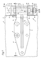
- FIG. 1 shows a hinge 1 for a closing element 2, in this case designed as a door leaf, for an opening 3 of a container 4.
- a closing element 2 On the closing element 2 there are flat-head screws with square shoulder 5 according to DIN 603, of which only one is shown in FIG. 1, a hinge leaf 6 attached.
- the hinge leaf 6 is pivotally mounted with a bearing head 7 on a hinge pin 9 defining the hinge axis 8.
- a hinge bearing 11 with a base 12 is welded to a frame 10 of the container 4 defining the opening 3 at the edge of the opening 3.
- the hinge bearing 11 has legs 13 and 14, between which the bearing head 7 is arranged and which carry the hinge pin 9.
- a nut 15 of the hinge pin 9 is secured by a spring ring 16 and a welding point 17.
- the bearing head 7 has two annular first projections 18 and 19 which extend axially outwards and are concentric with the hinge pin 9.
- the legs 13, 14 are each provided with an axially inwardly extending second projection 20 and 21, which axially overlaps the associated first projection 18, 19.
- Each second projection 20, 21 is designed as a circumferential holder arranged radially outside of the associated first projection 18, 19, which, according to FIG. 2, has a passage opening 23 for the associated first projection 19 on an end face 22 of the leg 14.
- a similar passage opening for the first projection 18 is located on the leg 13.
- the hinge leaf 6 is provided with a stiffening rib 24 in its longitudinal direction.
- the hinge leaf 6 could also be welded to the closing element 2 instead of being fastened by the round-head screws with a square socket 5.
- a transition 25 and 26 facing away from the base 12 from the bearing head 7 to the first projections 18, 19 is covered by a protective edge 27 and 28 on the associated second projection 20, 21. It is therefore impossible to saw through the hinge in the area of the transitions 25, 26 without this manipulation being noticed by the interested parties.
- a bearing bush 29 made of a fabric impregnated with plastic is arranged.
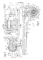
- FIG. 2 shows the closing element 2 with the hinge leaf 6 with solid lines in the closed position, in which an axis 30 of the hinge leaf 6 is inclined as indicated. 2, the closing element 2 and the hinge leaf 6 can be pivoted from this closed position counterclockwise about the hinge axis 8 to the limit position indicated by dash-dotted lines in FIG. 2, in which the closing element 2 runs practically parallel to the outer wall of the container 4 .
- the stiffening rib 24 is partially immersed in a complementary recess 31 in the base 12. One half of this recess 31 can be seen in another view in FIG. 4.
- the closure element 2 with the hinge leaf 6 can be moved during operation between the two limit positions shown in FIG. 2.
- the closed closing element 2 with its hinge leaves 6 is secured. Even if the hinge pin 9 were unauthorized to be removed from the hinge 1, the closing element 2 could not be lifted out because the first projections 18, 19 would then abut the surrounding second projections 20, 21. It would be sufficient for this securing if only the first projection 19 and the associated second projection 21 were present.
- the hinge leaf 6 is supported by the first projection 19 in this vertical arrangement of the hinge axis 8 in the sense of an axial bearing on the leg 14 of the hinge bearing 11.
- first pivoting angle 32 (FIG. 2), the size of which can be determined depending on the design features of the closing element 2 and the container 4.
- the axis 30 assumes the pivoting position 30 '.
- this pivoting position 30 ' there is a flattest point 33 of a cam 34 formed on the bearing head 7 in close proximity to a stop surface 35 of the base 12.
- a flattest point 33 of the cam 34 and a diametrically opposite point 36 on the circumference of the first projection 18 there is one Defined minimum dimension 37, which is smaller than the clear width of the passage opening 23.
- the closing element 2 with its hinge leaves 6 can practically only be moved through the passage openings 23 in their axial position 30 '.
- This definition of an assembly or disassembly position for the closing element 2 which is to be kept within any narrow limits increases the operational safety considerably. The operating personnel knows that only in this known assembly or disassembly position is there a risk that the closure element 2 can accidentally fall out of the hinge bearings 11 or be assembled or disassembled when the hinge pin 9 is removed.
- the cam 34 is expediently formed over the entire axial length of the bearing head 7 and in such a way that it is essentially circular in shape and towards the flattest point 33 with a decreasing radius.
- Fig. 3 shows the hinge leaf 6 in two positions important for assembly and disassembly, in which the axis is in the pivot position 30 '.
- the upper hinge leaf 6 in FIG. 3 is to be removed from the hinge bearing 11.
- the hinge pin has already been removed.
- the hinge leaf 6 is now moved with the flattest point 33 in contact with the stop surface 35 of the base 12.
- the flattest point 33 in FIG. 3 is then moved downward parallel to the stop surface 35 until the hinge leaf 6, according to its lower dash-dotted representation in FIG. 3, just passes through the passage opening 23.
- the longitudinal axis of the bearing head can also be moved on a quarter circle 38 shown in FIG. 3.
- all other types of movement between these two limit movements are also conceivable.
- the bearing bush 29 consists of bearing metal. Furthermore, in this exemplary embodiment, a protective edge corresponding to the protective edges 27, 28 in the previously described exemplary embodiment is dispensed with.
- Fig. 6 illustrates at the three different positions of the hinge leaf 6 entered there by dash-dotted lines that the hinge leaf 6 can also be assembled and disassembled relative to the hinge bearing 11 at a relatively small first swivel angle (see FIG. 32 in FIG. 2).
- first swivel angle see FIG. 32 in FIG. 2.
- only the flattest point 33 of the cam 34 lies at a different circumferential point than in the exemplary embodiment according to FIGS. 1 to 4. All other functions of the previously described exemplary embodiment are also retained in FIGS. 5 and 6.
- a hinge axis 40 is arranged horizontally.
- the hinge leaves 6 here carry a closure element 41 designed as a cover for the opening 42 of a container 43.
- the passage opening 23 is located at the bottom of the hinge bearing 11.
- the hinge bearing 11 according to FIG. 9 is designed without a protective edge corresponding to the protective edges 27 and 28 in FIGS. 7 and 8. However, such a protective edge can also be provided in FIG. 9.
- the second projection 21 on the leg 14 according to FIG. 9 has crenellated sections 44 distributed over the circumference of the leg 14.
- a peripheral opening 45 is defined in each case between adjacent sections 44 and between one of the sections 44 and the stop surface 35 of the base 12.
- the clear width of each circumferential opening 45 is smaller than a smallest dimension 46, in the case of FIG. 9 the diameter, of the first projection 19.
- the first swivel angle 32 covered thereby is smaller than the first swivel angle 32 required for mounting and dismounting the hinge leaf 6 according to FIG. 7.
- the passage opening 23 is only provided on the top of the leg 14, so that the hinge leaf 6 and thus the closing element 41 can only be removed upwards, e.g. on the quarter circle 38 can take place.
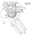
- the hinge bearing 11 shown in full lines in FIG. 10 has a vertical hinge axis 8, but could also be designed in the same way with a horizontal hinge axis.
- two opposite passage openings 47 and 48 are provided on the leg 14, which are delimited on both sides by sections of the second projection 21.
- a cam 49 is formed on the first projection 19.
- a minimum dimension 50 in the case of FIG. 10 is defined exclusively by the cam 49 and thus by the first projection 19.
- the closing element 2 is indicated in its closed position, in which the axis 30 of the hinge leaf 6 is as shown in FIG. 10. If the closing element 2 with the hinge leaf 6 is pivoted counterclockwise by the first pivot angle 32, the axis is in the pivot position 30 '. In this pivoted position, the hinge leaf 6 indicated by dash-dotted lines can either come out of the passage opening 47 or out of the passage opening 48, e.g. on the quarter circle 38, are removed from the hinge bearing 11.
- a larger or smaller first swivel angle 32 could also be used, but then the cam 49 would have to be arranged on the hinge leaf 6 in such a way that the minimum dimension 50 in the assembly and disassembly position is at least approximately parallel to the passage opening 47 or 48 in question.
- one of the passage openings 47, 48 could also be made impassable for the cam 49 either by continuously forming the second protrusion 21 or by inserting a section corresponding to the sections 44 in Fig. 9.
- the legs 13, 14 of all of the exemplary embodiments described above could also be equipped with two opposite passage openings corresponding to the passage openings 47, 48 in FIG. 10.
- the bearing head 7 of the hinge leaf 6 never comes into contact with the base 12 of the hinge bearing 11.
Landscapes
- Engineering & Computer Science (AREA)
- Mechanical Engineering (AREA)
- Hinges (AREA)
- Pivots And Pivotal Connections (AREA)
- Vehicle Step Arrangements And Article Storage (AREA)
Claims (8)
Priority Applications (1)
| Application Number | Priority Date | Filing Date | Title |
|---|---|---|---|
| AT86115768T ATE40172T1 (de) | 1985-12-07 | 1986-11-13 | Scharnier. |
Applications Claiming Priority (2)
| Application Number | Priority Date | Filing Date | Title |
|---|---|---|---|
| DE8534442U DE8534442U1 (de) | 1985-12-07 | 1985-12-07 | Scharnier |
| DE8534442U | 1985-12-07 |
Publications (2)
| Publication Number | Publication Date |
|---|---|
| EP0226046A1 EP0226046A1 (fr) | 1987-06-24 |
| EP0226046B1 true EP0226046B1 (fr) | 1989-01-18 |
Family
ID=6788004
Family Applications (1)
| Application Number | Title | Priority Date | Filing Date |
|---|---|---|---|
| EP86115768A Expired EP0226046B1 (fr) | 1985-12-07 | 1986-11-13 | Charnière |
Country Status (5)
| Country | Link |
|---|---|
| US (1) | US4756055A (fr) |
| EP (1) | EP0226046B1 (fr) |
| AT (1) | ATE40172T1 (fr) |
| DE (2) | DE8534442U1 (fr) |
| ES (1) | ES2005809B3 (fr) |
Families Citing this family (10)
| Publication number | Priority date | Publication date | Assignee | Title |
|---|---|---|---|---|
| DE10118301B4 (de) * | 2001-04-12 | 2011-01-20 | Brückner, Lothar, Dr. | Kraftwagentürscharnier |
| EP0286562B1 (fr) * | 1987-04-07 | 1992-03-11 | Pont-A-Mousson S.A. | Regard de chaussée à charnière en T |
| CH677244A5 (fr) * | 1988-07-05 | 1991-04-30 | Von Roll Ag | |
| DE8812152U1 (de) * | 1988-09-26 | 1988-11-10 | F. Hesterberg & Söhne GmbH & Co KG, 5828 Ennepetal | Scharnier für Türen von Fahrzeugkofferaufbauten, Containern u.dgl. mit einer Zollsicherung |
| GB2247495B (en) * | 1990-08-31 | 1994-01-19 | Nicholls & Clarke Limited | Pivot assembly |
| ZA935152B (en) * | 1992-10-06 | 1994-02-09 | Transnet Ltd | Hinge having tamper-proof hinge pin |
| US6182313B1 (en) * | 1999-03-22 | 2001-02-06 | Paul William Eschenbach | Therapeutic head cradle |
| AU2002309987A1 (en) * | 2001-05-25 | 2002-12-09 | Hill-Rom Services, Inc. | Modular patient room |
| US20050241662A1 (en) * | 2004-04-28 | 2005-11-03 | Sheffler Robert J | Abraded spiral wound brush |
| US8443490B2 (en) * | 2007-06-05 | 2013-05-21 | Liberty Hardware Mfg. Corp. | Universal reversible gate hinges and method of assembly |
Family Cites Families (11)
| Publication number | Priority date | Publication date | Assignee | Title |
|---|---|---|---|---|
| US770595A (en) * | 1904-09-20 | Hinge | ||
| US2677147A (en) * | 1950-10-07 | 1954-05-04 | Int Harvester Co | Separable hinge |
| US2742664A (en) * | 1953-09-11 | 1956-04-24 | Pennant Corp | Hinge construction |
| CH531436A (de) * | 1971-11-05 | 1972-12-15 | Saurer Ag Adolph | Scharnier für klappbare Fahrzeugbrückenwände |
| DE2223904B2 (de) * | 1972-05-17 | 1978-07-27 | Wohlfarth Transport Kg, 7000 Stuttgart | Scharnier für Bordwände von Nutzfahrzeugen |
| DE2317039C3 (de) * | 1973-04-05 | 1987-02-12 | Siegenia-Frank Kg, 5900 Siegen | Scharniergelenk für Fenster, Türen o.dgl. |
| DE3245205A1 (de) * | 1981-12-09 | 1983-07-21 | F. Hesterberg & Söhne GmbH & Co KG, 5828 Ennepetal | Scharnier fuer tueren von fahrzeugkofferaufbauten, containern und dergleichen mit einer zollsicherung |
| DE3268432D1 (en) * | 1982-09-27 | 1986-02-20 | Hesterberg & Soehne F | Hinge for tiltable and disconnectable side boards with a security member |
| DE3341855A1 (de) * | 1983-11-19 | 1985-06-13 | Otto Berns GmbH, 5970 Plettenberg | Scharnier fuer tueren von kraftfahrzeug-kofferaufbauten, containern oder dergleichen |
| DE3401245A1 (de) * | 1984-01-16 | 1985-07-18 | Lunke & Sohn Gmbh, 5810 Witten | Tuerscharnier fuer ein kraftfahrzeug |
| US4603452A (en) * | 1985-01-22 | 1986-08-05 | General Dynamics Corporation | Detachable hinge with conveniently releasable hinge flaps |
-
1985
- 1985-12-07 DE DE8534442U patent/DE8534442U1/de not_active Expired
-
1986
- 1986-11-13 EP EP86115768A patent/EP0226046B1/fr not_active Expired
- 1986-11-13 ES ES86115768T patent/ES2005809B3/es not_active Expired
- 1986-11-13 AT AT86115768T patent/ATE40172T1/de not_active IP Right Cessation
- 1986-11-13 DE DE8686115768T patent/DE3661854D1/de not_active Expired
- 1986-12-05 US US06/938,790 patent/US4756055A/en not_active Expired - Fee Related
Also Published As
| Publication number | Publication date |
|---|---|
| ES2005809B3 (es) | 1989-03-16 |
| DE8534442U1 (de) | 1986-06-26 |
| US4756055A (en) | 1988-07-12 |
| DE3661854D1 (en) | 1989-02-23 |
| EP0226046A1 (fr) | 1987-06-24 |
| ATE40172T1 (de) | 1989-02-15 |
Similar Documents
| Publication | Publication Date | Title |
|---|---|---|
| EP0127011B1 (fr) | Charnière avec élément de sécurité | |
| DE3612878C2 (fr) | ||
| DE19949185A1 (de) | Türscharnier | |
| EP0226046A1 (fr) | Charnière | |
| DE19521067A1 (de) | Mähscheibe mit Klingenbefestigung für Rotationsmähwerk | |
| DE2628951A1 (de) | Aushaengbares scharnier, insbesondere fuer kraftfahrzeuge | |
| AT394130B (de) | Schwenkarmvorrichtung | |
| EP0708219A1 (fr) | Ferrure ou similaire, de préférence partie charnière, avec dispositif de fixation | |
| EP0845568B1 (fr) | Charnière dégondable pour portes de véhicule | |
| DE69707091T2 (de) | Schwenkbare Steckdosenhaltevorrichtung | |
| DE3414401C2 (fr) | ||
| DE3137112C2 (fr) | ||
| EP1068417B1 (fr) | Element d'arret de portiere integre a une charniere de portiere demontable | |
| EP0825318A2 (fr) | Charnière de porte décrochable à arrêtoir de porte intégré | |
| DE29621946U1 (de) | Aushängbares Türscharnier für Kraftwagentüren | |
| EP0104268B1 (fr) | Charnière pour ridelles rabattables et décrochables avec un élément de sécurité | |
| DE19723401C1 (de) | Aushängbares Türscharnier | |
| EP3574813B1 (fr) | Charnière pour un ensemble d'un siège de toilettes | |
| DE3400147C1 (de) | Trennbares Scharnier, insbesondere für Kraftfahrzeugtüren | |
| DE3341855A1 (de) | Scharnier fuer tueren von kraftfahrzeug-kofferaufbauten, containern oder dergleichen | |
| DE4024370C2 (fr) | ||
| DE102004025389B4 (de) | Scharnier zum schwenkbaren Haltern einer Tür | |
| DE202013009757U1 (de) | Insektenschutzdrehtür | |
| DE4420627C1 (de) | Pflug mit Pflugkörperschwenkvorrichtung | |
| DE3407624A1 (de) | Haltevorrichtung fuer ein werkzeug, insbesondere schutzgasschweissbrenner, in einem programmgesteuerten handhabungsautomaten |
Legal Events
| Date | Code | Title | Description |
|---|---|---|---|
| PUAI | Public reference made under article 153(3) epc to a published international application that has entered the european phase |
Free format text: ORIGINAL CODE: 0009012 |
|
| AK | Designated contracting states |
Kind code of ref document: A1 Designated state(s): AT BE CH DE ES FR GB IT LI LU NL SE |
|
| 17P | Request for examination filed |
Effective date: 19870511 |
|
| 17Q | First examination report despatched |
Effective date: 19871022 |
|
| GRAA | (expected) grant |
Free format text: ORIGINAL CODE: 0009210 |
|
| AK | Designated contracting states |
Kind code of ref document: B1 Designated state(s): AT BE CH DE ES FR GB IT LI LU NL SE |
|
| REF | Corresponds to: |
Ref document number: 40172 Country of ref document: AT Date of ref document: 19890215 Kind code of ref document: T |
|
| GBT | Gb: translation of ep patent filed (gb section 77(6)(a)/1977) | ||
| REF | Corresponds to: |
Ref document number: 3661854 Country of ref document: DE Date of ref document: 19890223 |
|
| ITF | It: translation for a ep patent filed | ||
| ET | Fr: translation filed | ||
| PLBE | No opposition filed within time limit |
Free format text: ORIGINAL CODE: 0009261 |
|
| STAA | Information on the status of an ep patent application or granted ep patent |
Free format text: STATUS: NO OPPOSITION FILED WITHIN TIME LIMIT |
|
| 26N | No opposition filed | ||
| ITTA | It: last paid annual fee | ||
| PGFP | Annual fee paid to national office [announced via postgrant information from national office to epo] |
Ref country code: LU Payment date: 19920923 Year of fee payment: 7 |
|
| PGFP | Annual fee paid to national office [announced via postgrant information from national office to epo] |
Ref country code: CH Payment date: 19921217 Year of fee payment: 7 |
|
| EPTA | Lu: last paid annual fee | ||
| PGFP | Annual fee paid to national office [announced via postgrant information from national office to epo] |
Ref country code: FR Payment date: 19930914 Year of fee payment: 8 |
|
| PGFP | Annual fee paid to national office [announced via postgrant information from national office to epo] |
Ref country code: ES Payment date: 19930923 Year of fee payment: 8 |
|
| PGFP | Annual fee paid to national office [announced via postgrant information from national office to epo] |
Ref country code: GB Payment date: 19931103 Year of fee payment: 8 |
|
| PG25 | Lapsed in a contracting state [announced via postgrant information from national office to epo] |
Ref country code: LU Free format text: LAPSE BECAUSE OF NON-PAYMENT OF DUE FEES Effective date: 19931113 |
|
| PG25 | Lapsed in a contracting state [announced via postgrant information from national office to epo] |
Ref country code: LI Effective date: 19931130 Ref country code: CH Effective date: 19931130 |
|
| PGFP | Annual fee paid to national office [announced via postgrant information from national office to epo] |
Ref country code: SE Payment date: 19931130 Year of fee payment: 8 Ref country code: AT Payment date: 19931130 Year of fee payment: 8 |
|
| REG | Reference to a national code |
Ref country code: CH Ref legal event code: PL |
|
| PG25 | Lapsed in a contracting state [announced via postgrant information from national office to epo] |
Ref country code: GB Effective date: 19941113 Ref country code: AT Effective date: 19941113 |
|
| PG25 | Lapsed in a contracting state [announced via postgrant information from national office to epo] |
Ref country code: SE Effective date: 19941114 Ref country code: ES Free format text: LAPSE BECAUSE OF EXPIRATION OF PROTECTION Effective date: 19941114 |
|
| EAL | Se: european patent in force in sweden |
Ref document number: 86115768.3 |
|
| GBPC | Gb: european patent ceased through non-payment of renewal fee |
Effective date: 19941113 |
|
| PG25 | Lapsed in a contracting state [announced via postgrant information from national office to epo] |
Ref country code: FR Effective date: 19950731 |
|
| EUG | Se: european patent has lapsed |
Ref document number: 86115768.3 |
|
| REG | Reference to a national code |
Ref country code: FR Ref legal event code: ST |
|
| PGFP | Annual fee paid to national office [announced via postgrant information from national office to epo] |
Ref country code: BE Payment date: 19951129 Year of fee payment: 10 |
|
| PGFP | Annual fee paid to national office [announced via postgrant information from national office to epo] |
Ref country code: NL Payment date: 19951130 Year of fee payment: 10 |
|
| PG25 | Lapsed in a contracting state [announced via postgrant information from national office to epo] |
Ref country code: BE Effective date: 19961130 |
|
| BERE | Be: lapsed |
Owner name: CARL SULBERG G.M.B.H. & CO. Effective date: 19961130 |
|
| PG25 | Lapsed in a contracting state [announced via postgrant information from national office to epo] |
Ref country code: NL Effective date: 19970601 |
|
| NLV4 | Nl: lapsed or anulled due to non-payment of the annual fee |
Effective date: 19970601 |
|
| PGFP | Annual fee paid to national office [announced via postgrant information from national office to epo] |
Ref country code: DE Payment date: 19981207 Year of fee payment: 13 |
|
| PG25 | Lapsed in a contracting state [announced via postgrant information from national office to epo] |
Ref country code: DE Free format text: LAPSE BECAUSE OF NON-PAYMENT OF DUE FEES Effective date: 20000901 |
|
| REG | Reference to a national code |
Ref country code: ES Ref legal event code: FD2A Effective date: 20010301 |
|
| PG25 | Lapsed in a contracting state [announced via postgrant information from national office to epo] |
Ref country code: IT Free format text: LAPSE BECAUSE OF NON-PAYMENT OF DUE FEES;WARNING: LAPSES OF ITALIAN PATENTS WITH EFFECTIVE DATE BEFORE 2007 MAY HAVE OCCURRED AT ANY TIME BEFORE 2007. THE CORRECT EFFECTIVE DATE MAY BE DIFFERENT FROM THE ONE RECORDED. Effective date: 20051113 |